1987 SUZUKI GRAND VITARA service
[x] Cancel search: servicePage 110 of 962
3-7. ENGINE INSTALLATION
1) Lower engine with transmission into vehicle,
but do not remove lifting device.
2) Tighten engine mounting bracket bolts
(right and left) and transmission mounting
bolts to specification. Refer to p. 3-58.
3) Remove lifting device.
4) Reverse removal procedures for installation
of remainder.
5) Adjust accelerator cable play and clutch
cable play.
6) Connect vacuum hoses securely. Refer to
section 5 “EMISSION CONTROL SYSTEM”
for correct connection.
7) Connect wire harnesses and couplers secure-
IY.
8) Tighten bolts and nuts to specified torque.
For individual specification, refer to each
section.
9) Fill specified amount of specified trans-
mission oil and engine oil. For the detail,
refer to SECTION 1 PERIODIC MAINTE-
NANCE SERVICE of this manual.
10) After adjusting water pump belt tension to
specification, fill specified amount of engine
cooling water.
11) Before starting engine, check again to ensure
that all parts once disassembled or discon-
nected are back in place securely.
12)Start engine and check ignition timing. If
it is not to specified timing, adjust it, referr-
ing to SECTION 8 of this manual.
13) After engine is started, check for oil leak,
abnormal noise and other malcondition.
Also, check each part for operation.
3-8. ENGINE MAINTENANCE SERVICE
Fan Belt
Adjust belt tension as outlined in SECTION 6
ENGINE COOLING SYSTEM (p. 6-10).
Ignition Timing
Refer to IGNITION TIMING, Page 8-9.
Carburetor
fidjustments to be made are detailed in SEC-
TION 4 (p. 4-19).
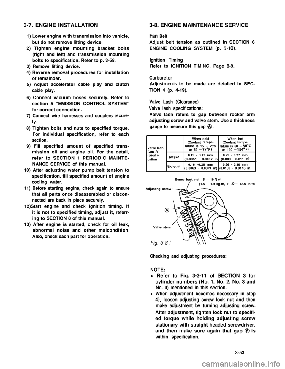
Valve Lash (Clearance)
Valve lash specifications:
Valve lash refers to gap between rocker arm
adjusting screw and valve stem. Use a thickness
gauge to measure this gap @.
When coldWhen hot(Coolant tempe-(Coolant tempa-
Valve lashrature is 15 - 25%rature is 60 - 66’C
(gap A)or 69 - 77’F)or 140 - 154’F)
specif i-0.13 - 0.17 mm0.23 - 0.27 mmcationIntake(0.0051 - 0.0067 in) (0.009 - 0.011 in)
Exhaust0.16 -0.20 mm0.26 - 0.30 mm(0.0063 - 0.0079 in) (0.0102 - 0.0116 in)
Screw lock nut 15 - 19 N.m(1.5 - 1.9 kg-m, 11 .O - 13.5 lb-ft)
Adjusting screw
8
Valve stem
Fig. 3-8-l
Checking and adjusting procedures:
NOTE:
l Refer to Fig. 3-3-11 of SECTION 3 for
cylinder numbers (No. 1, No. 2, No. 3 and
No. 4) mentioned in this section.
l When adjustment becomes necessary in step
4), loosen adjusting screw lock nut and then
make adjustment by turning adjusting screw.
After adjustment, tighten lock nut to specifi-
ed torque while holding adjusting screw
stationary with straight headed screwdriver,
and then make sure again that gap @ is
within specification.
3-53
Page 116 of 962

SECTION 4
FUEL SYSTEM
CONTENTS
4-1.CARBURETOR.............................................4-2
GENERAL DESCRIPTION.................................4-2
REMOVAL AND INSTALLATION...........................4-12
UNIT REPAIR OVERHAUL...............................4-13
MAINTENANCE SERVICES...............................4-19
4-2.AIR CLEANER...........................................4-29
GENERAL DESCRIPTION.................................4-29
MAINTENANCE SERVICES...............................4-29
4-3.FUEL PUMP, FILTER AND LINES...........................4-31
GENERAL DESCRIPTION.................................4-31
REMOVAL AND INSTALLATION...........................4-33
MAINTENANCE SERVICES...............................4-35
4-4.ACCELERATOR PEDAL...................................4-36
CAUTION:
THE ENGINE OF THIS VEHICLE REQUIRED THE USE OF UNLEADED FUEL ONLY.
USE OF LEADED AND/OR LOW LEAD FUEL CAN RESULT IN ENGINE DAMAGE AND RE-
DUCE THE EFFECTIVENESS OF THE EMISSION CONTROL SYSTEMS.
4-1
4
Page 132 of 962
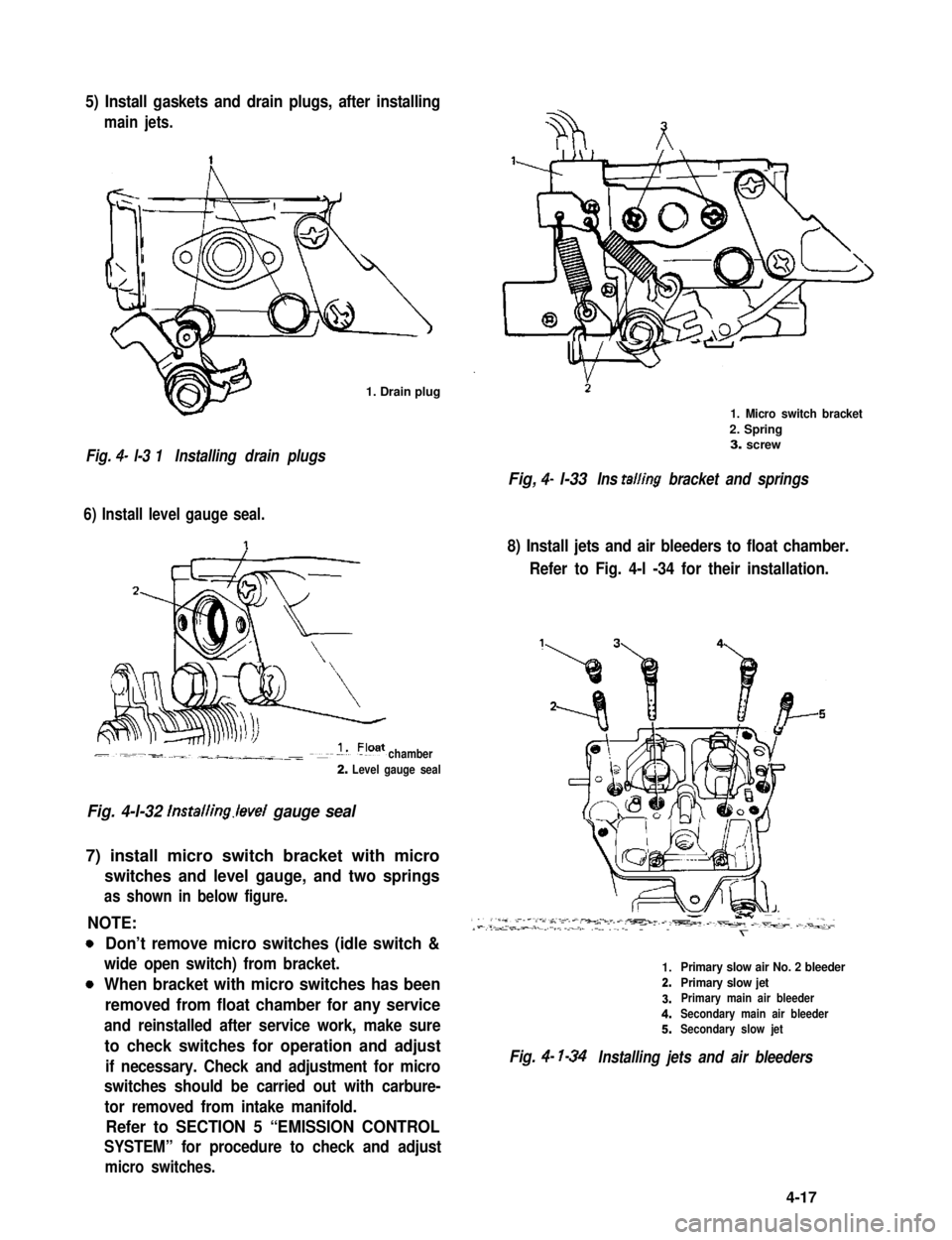
5) Install gaskets and drain plugs, after installing
main jets.
1. Drain plug
Fig. 4- l-3 1Installing drain plugs
6) Install level gauge seal.
chamber
2. Level gauge seal
Fig. 4-l-32 lnstalling.level gauge seal
7) install micro switch bracket with micro
switches and level gauge, and two springs
as shown in below figure.
NOTE:
0
0
Don’t remove micro switches (idle switch &
wide open switch) from bracket.
When bracket with micro switches has been
removed from float chamber for any service
and reinstalled after service work, make sure
to check switches for operation and adjust
if necessary. Check and adjustment for micro
switches should be carried out with carbure-
tor removed from intake manifold.
Refer to SECTION 5 “EMISSION CONTROL
SYSTEM” for procedure to check and adjust
micro switches.
1. Micro switch bracket
2. Spring3. screw
Fig, 4- l-33Ins tailing bracket and springs
8) Install jets and air bleeders to float chamber.
Refer to Fig. 4-l -34 for their installation.
1.Primary slow air No. 2 bleeder
2.Primary slow jet
3.Primary main air bleeder
4.Secondary main air bleeder
5.Secondary slow jet
Fig. 4- l-34Installing jets and air bleeders
4-17
Page 134 of 962
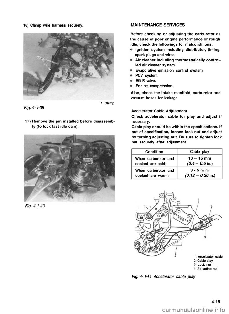
16) Clamp wire harness securely.MAINTENANCE SERVICES
Fig. 4- l-39
1. Clamp
17) Remove the pin installed before disassemb-
ly (to lock fast idle cam).
Fig. 4- l-40
Before checking or adjusting the carburetor as
the cause of poor engine performance or rough
idle, check the followings for malconditions.
Ignition system including distributor, timing,
spark plugs and wires.
Air cleaner including thermostatically control-
led air cleaner system.
Evaporative emission control system.
PCV system.
EG R valve.
Engine compression.
Also, check the intake manifold, carburetor and
vacuum hoses for leakage.
Accelerator Cable Adjustment
Check accelerator cable for play and adjust if
necessary.
Cable play should be within the specifications. If
out of specification, loosen lock nut and adjust
by turning adjusting nut. Be sure to tighten lock
nut securely after adjustment.
Condition
When carburetor and
coolant are cold;
When carburetor and
coolant are warm;
Cable play
10 - 15 mm
(0.4 - 0.6 in.)
3-5mm
(0.12 - 0.20 in.)
1. Accelerator cable
2. Cable play
3. Lock nut
4. Adjusting nut
Fig. 4- l-4 1 Accelerator cable play
4-19
Page 141 of 962
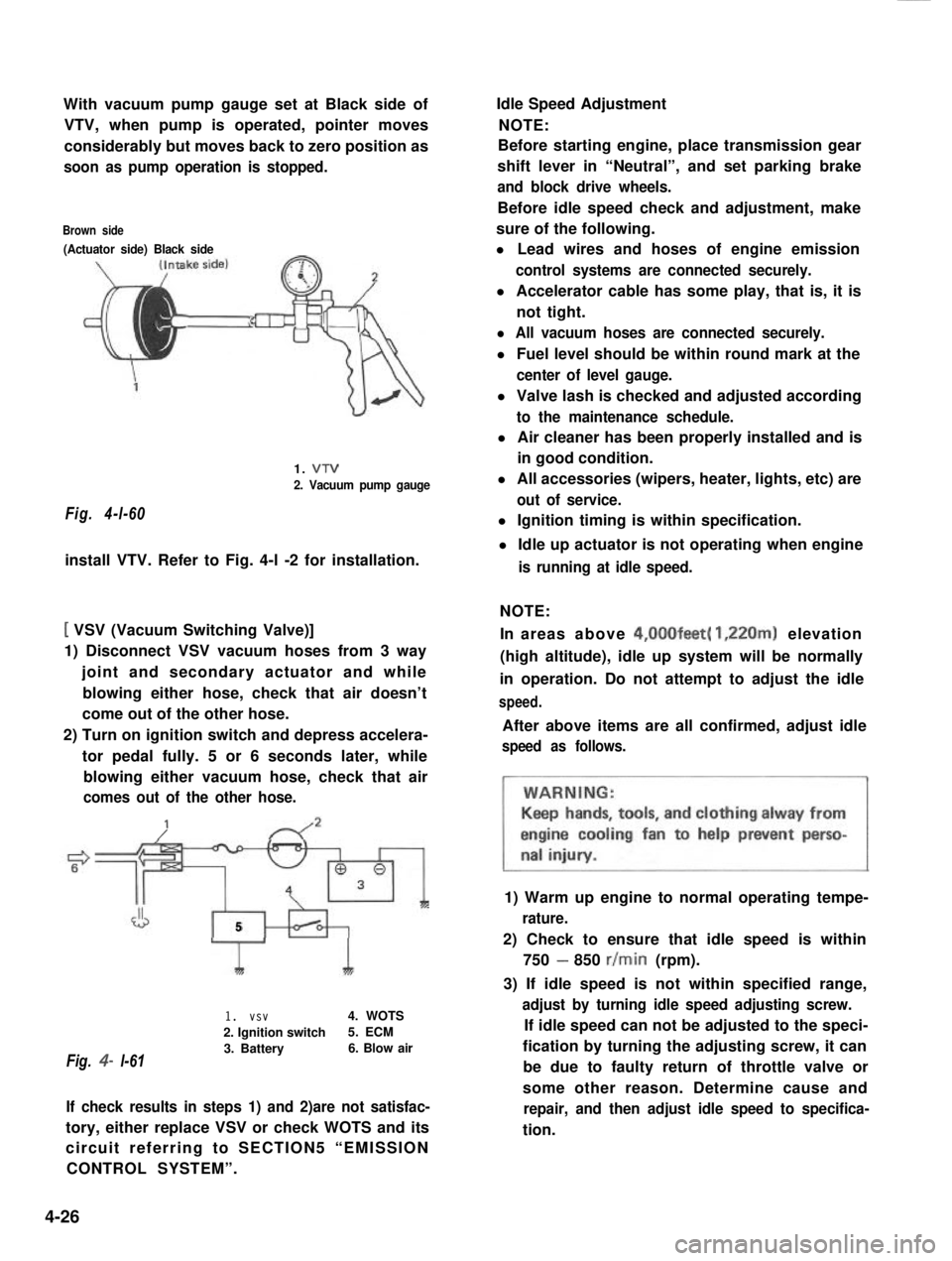
With vacuum pump gauge set at Black side of
VTV, when pump is operated, pointer moves
considerably but moves back to zero position as
soon as pump operation is stopped.
Brown side
(Actuator side) Black side
Fig. 4-l-60
1. VTV
2. Vacuum pump gauge
install VTV. Refer to Fig. 4-l -2 for installation.
[ VSV (Vacuum Switching Valve)]
1) Disconnect VSV vacuum hoses from 3 way
joint and secondary actuator and while
blowing either hose, check that air doesn’t
come out of the other hose.
2) Turn on ignition switch and depress accelera-
tor pedal fully. 5 or 6 seconds later, while
blowing either vacuum hose, check that air
comes out of the other hose.
J5
Fig. 4- l-61
1I
1. vsv4. WOTS
2. Ignition switch5. ECM
3. Battery6. Blow air
If check results in steps 1) and 2)are not satisfac-
tory, either replace VSV or check WOTS and its
circuit referring to SECTION5 “EMISSION
CONTROL SYSTEM”.
Idle Speed Adjustment
NOTE:
Before starting engine, place transmission gear
shift lever in “Neutral”, and set parking brake
and block drive wheels.
Before idle speed check and adjustment, make
sure of the following.
l Lead wires and hoses of engine emission
control systems are connected securely.
l Accelerator cable has some play, that is, it is
not tight.
l All vacuum hoses are connected securely.
l Fuel level should be within round mark at the
center of level gauge.
l Valve lash is checked and adjusted according
to the maintenance schedule.
l Air cleaner has been properly installed and is
in good condition.
l All accessories (wipers, heater, lights, etc) are
out of service.
l Ignition timing is within specification.
l Idle up actuator is not operating when engine
is running at idle speed.
NOTE:
In areas above 4,00Ofeet( 1,220m) elevation
(high altitude), idle up system will be normally
in operation. Do not attempt to adjust the idle
speed.
After above items are all confirmed, adjust idle
speed as follows.
1) Warm up engine to normal operating tempe-
rature.
2) Check to ensure that idle speed is within
750 - 850 r/min (rpm).
3) If idle speed is not within specified range,
adjust by turning idle speed adjusting screw.
If idle speed can not be adjusted to the speci-
fication by turning the adjusting screw, it can
be due to faulty return of throttle valve or
some other reason. Determine cause and
repair, and then adjust idle speed to specifica-
tion.
4-26
Page 142 of 962
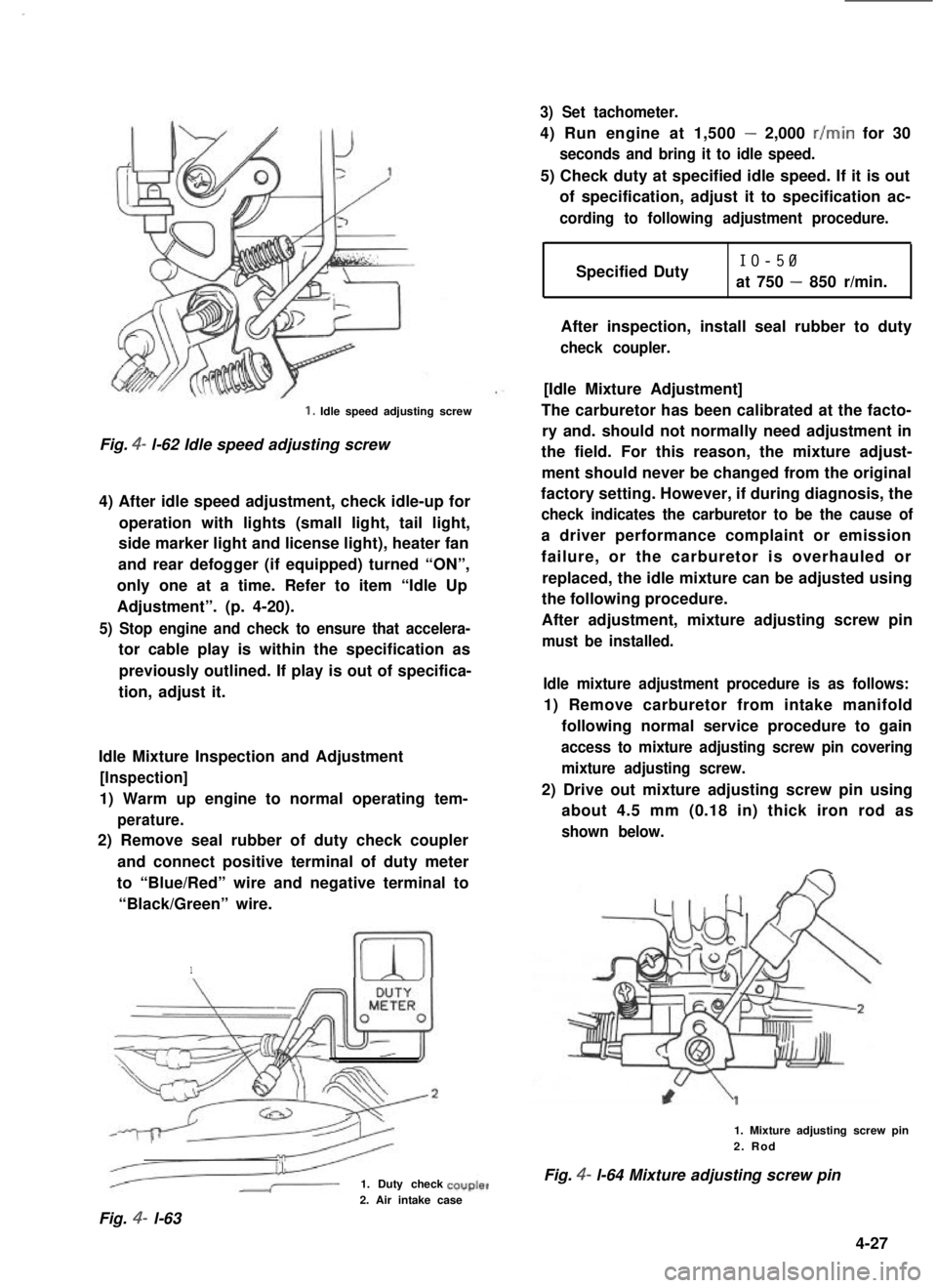
1. Idle speed adjusting screw
Fig. 4- l-62 Idle speed adjusting screw
4) After idle speed adjustment, check idle-up for
operation with lights (small light, tail light,
side marker light and license light), heater fan
and rear defogger (if equipped) turned “ON”,
only one at a time. Refer to item “Idle Up
Adjustment”. (p. 4-20).
5) Stop engine and check to ensure that accelera-
tor cable play is within the specification as
previously outlined. If play is out of specifica-
tion, adjust it.
Idle Mixture Inspection and Adjustment
[Inspection]
1) Warm up engine to normal operating tem-
perature.
2) Remove seal rubber of duty check coupler
and connect positive terminal of duty meter
to “Blue/Red” wire and negative terminal to
“Black/Green” wire.
1
1. Duty check
3) Set tachometer.
4) Run engine at 1,500 - 2,000 r/min for 30
seconds and bring it to idle speed.
5) Check duty at specified idle speed. If it is out
of specification, adjust it to specification ac-
cording to following adjustment procedure.
Specified DutyIO-50
at 750 - 850 r/min.
After inspection, install seal rubber to duty
check coupler.
[Idle Mixture Adjustment]
The carburetor has been calibrated at the facto-
ry and. should not normally need adjustment in
the field. For this reason, the mixture adjust-
ment should never be changed from the original
factory setting. However, if during diagnosis, the
check indicates the carburetor to be the cause of
a driver performance complaint or emission
failure, or the carburetor is overhauled or
replaced, the idle mixture can be adjusted using
the following procedure.
After adjustment, mixture adjusting screw pin
must be installed.
Idle mixture adjustment procedure is as follows:
1) Remove carburetor from intake manifold
following normal service procedure to gain
access to mixture adjusting screw pin covering
mixture adjusting screw.
2) Drive out mixture adjusting screw pin using
about 4.5 mm (0.18 in) thick iron rod as
shown below.
1. Mixture adjusting screw pin2. Rod
Fig. 4- l-64 Mixture adjusting screw pin
2. Air intake case
Fig. 4- l-63
4-27
Page 143 of 962

3) Reinstall carburetor following normal service
procedures.
Connect emission control system hoses and
lead wires. Make specified play on accelerator
cable and refill cooling system.
4) Place transaxle gear shift lever in “Neutral”,
set parking brake and block drive wheels.
5) Start engine, and warm it up to normal
operating temperature, stop engine.
6) Be sure to check the following before idle
mixture adjustment.
l Fuel level is within round mark at the
center of level gauge.
l Valve lash is checked and adjusted accord-
ing to the maintenance schedule.
l Air cleaner has been properly installed
and is in good condition.
l All accessories (wipers, heater, lights etc)
are out of service.
l Ignition timing is within specification.
l Choke valve opens fully.
l Idle-up actuator does not operate.
7) Check and adjust idle speed to specification
if necessary.
8) Remove seal rubber of duty check coupler
and connect positive terminal of duty
meter to“Blue/Red” wire and negative
terminal to “Black/Green” wire.
9) Run engine at 1,500 - 2,000 r/min for 30
seconds and bring it to idle speed.
10) With engine running at idle speed, adjust idle
mixture adjusting screw slowly in small incre-
ment allowing time for duty to stabilize after
turning screw to obtain duty of 10 - 50.
If duty is too low, back screw out; if too
high, screw it in. After obtaining duty of
10 - 50, recheck idle speed, and adjust if
necessary.
NOTE:
If adjustment can’t be made because duty meter
indicator does not deflect, check feed back
system according to the checking procedure of
system described in section of Emission Control
System.
11) After adjustment, install seal rubber to duty
check coupler and drive in idle mixture
adjusting screw pin.
4-28
Page 144 of 962
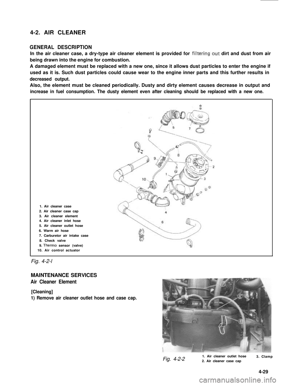
4-2. AIR CLEANER
GENERAL DESCRIPTION
In the air cleaner case, a dry-type air cleaner element is provided for filtering.out dirt and dust from air
being drawn into the engine for combustion.
A damaged element must be replaced with a new one, since it allows dust particles to enter the engine if
used as it is. Such dust particles could cause wear to the engine inner parts and this further results in
decreased output.
Also, the element must be cleaned periodically. Dusty and dirty element causes decrease in output and
increase in fuel consumption. The dusty element even after cleaning should be replaced with a new one.
Fig. 4-2-l
1. Air cleaner case
2. Air cleaner case cap
3. Air cleaner element4. Air cleaner inlet hose
5. Air cleaner outlet hose
6. Warm air hose
7. Carburetor air intake case
8. Check valve
9. Therm0 sensor (valve)10. Air control actuator
MAINTENANCE SERVICES
Air Cleaner Element
[Cleaning]
1) Remove air cleaner outlet hose and case cap.
Fig. 4-2-21. Air cleaner outlet hose2. Air cleaner case cap3. Clamp
4-29