1987 MAZDA 626 width
[x] Cancel search: widthPage 84 of 1865
1A INSPECTION AND REPAIR
76G01A-128
86U01X-088
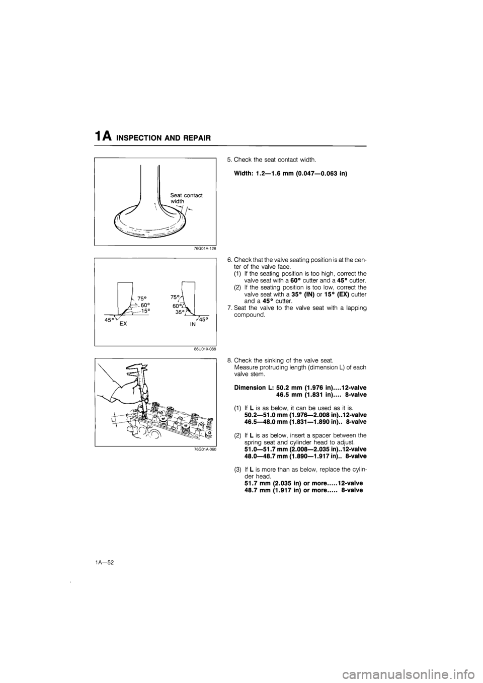
5. Check the seat contact width.
Width: 1.2—1.6 mm (0.047—0.063 in)
6. Check that the valve seating position is at the cen-
ter of the valve face.
(1) If the seating position is too high, correct the
valve seat with a 60° cutter and a 45° cutter.
(2) If the seating position is too low, correct the
valve seat with a 35° (IN) or 15° (EX) cutter
and a 45° cutter.
7. Seat the valve to the valve seat with a lapping
compound.
76G01A-060
8. Check the sinking of the valve seat.
Measure protruding length (dimension L) of each
valve stem.
Dimension L: 50.2 mm (1.976 in).... 12-valve
46.5 mm (1.831 in).... 8-valve
(1) If L is as below, it can be used as it is.
50.2—51.0 mm (1.976—2.008 in)..12-valve
46.5—48.0 mm (1.831—1.890 in).. 8-valve
(2) If L is as below, insert a spacer between the
spring seat and cylinder head to adjust.
51.0—51.7 mm (2.008—2.035 in)..12-valve
48.0—48.7 mm (1.890—1.917 in).. 8-valve
(3) If L is more than as below, replace the cylin-
der head.
51.7 mm (2.035 in) or more 12-valve
48.7 mm (1.917 in) or more 8-valve
1A—52
Page 98 of 1865
1 A ASSEMBLY (CYLINDER BLOCK)
76G01A-074
86U01X-216
86U01X-127
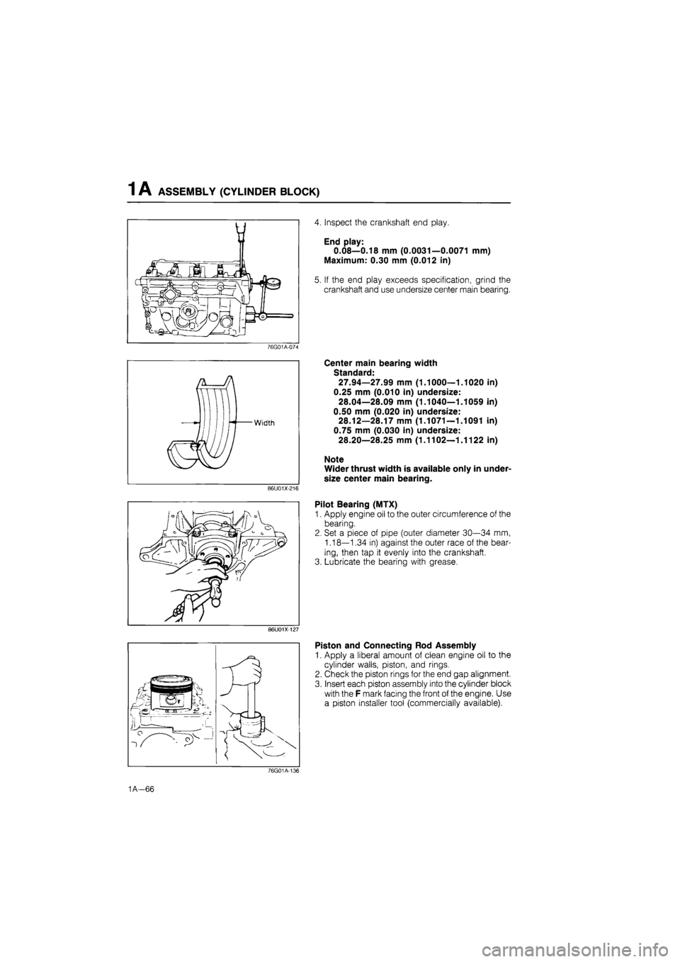
4. Inspect the crankshaft end play.
End play:
0.08—0.18 mm (0.0031—0.0071 mm)
Maximum: 0.30 mm (0.012 in)
5. If the end play exceeds specification, grind the
crankshaft and use undersize center main bearing.
Center main bearing width
Standard:
27.94—27.99 mm (1.1000—1.1020 in)
0.25 mm (0.010 in) undersize:
28.04—28.09 mm (1.1040—1.1059 in)
0.50 mm (0.020 in) undersize:
28.12—28.17 mm (1.1071—1.1091 in)
0.75 mm (0.030 in) undersize:
28.20—28.25 mm (1.1102—1.1122 in)
Note
Wider thrust width is available only in under-
size center main bearing.
Pilot Bearing (MTX)
1. Apply engine oil to the outer circumference of the
bearing.
2. Set a piece of pipe (outer diameter 30—34 mm,
1.18—1.34 in) against the outer race of the bear-
ing, then tap it evenly into the crankshaft.
3. Lubricate the bearing with grease.
Piston and Connecting Rod Assembly
1. Apply a liberal amount of clean engine oil to the
cylinder walls, piston, and rings.
2. Check the piston rings for the end gap alignment.
3. Insert each piston assembly into the cylinder block
with the F mark facing the front of the engine. Use
a piston installer tool (commercially available).
76G01A-136
1A—66
Page 169 of 1865

INSPECTION AND REPAIR 1 B
76G01A-128
L 75° 75/ 60° 60
35°>
450 V EX '%50 IN
86U01X-088
76G01B-055
5. Check the seat contact width.
Width: 1.2—1.6 mm (0.047—0.063 in)
6. Check that the valve seating position is at the cen-
ter of the valve face.
(1) If the seating position is too high, correct the
valve seat with a 60° cutter and a 45° cutter.
(2) If the seating position is too low, correct the
valve seat with a 35° (IN) or 15° (EX) cutter
and a 45° cutter.
7. Seat the valve to the valve seat with a lapping
compound.
8. Check the sinking of the valve seat.
Measure protruding length (dimension L) of each
valve stem.
Dimension L: 36.8 mm (1.449 in)
(1) If L is as below, it can be used as it is.
36.8—37.6 mm (1.449—1.480 in)
(2) If L is as below, insert a spacer between the
spring seat and cylinder head to adjust.
37.6—38.3 mm (1.480—1.508 in)
(3) If L is more than as below, replace the cylin-
der head.
38.3 mm (1.508 in) or more
Valve Spring 1. Inspect each valve spring for cracks or damage.
2. Check the free length and angle. Replace if
necessary.
Free length
Outer Standard: 39.1 mm (1.539 in)
Minimum: 38.7 mm (1.524 in)
Inner Standard: 38.0 mm (1.496 in)
Minimum: 37.7 mm (1.484 in)
76G01B-059
1B-38
Page 183 of 1865
1 B ASSEMBLY (CYLINDER BLOCK)
76G01A-074
86U01X-216
76G01 B-075
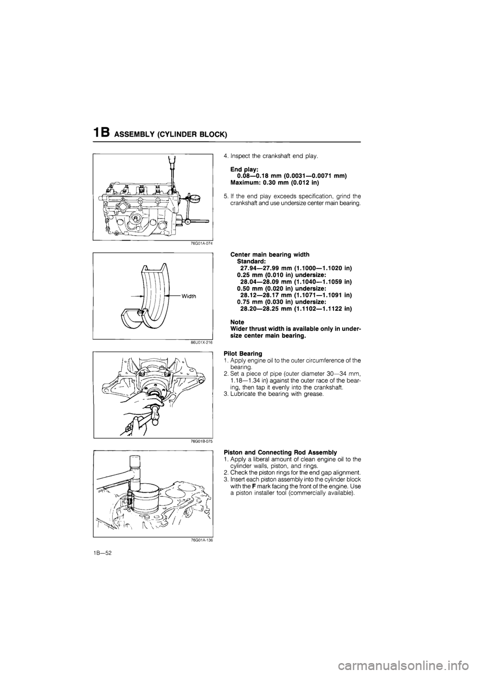
4. Inspect the crankshaft end play.
End play:
0.08—0.18 mm (0.0031—0.0071 mm)
Maximum: 0.30 mm (0.012 in)
5. If the end play exceeds specification, grind the
crankshaft and use undersize center main bearing.
Center main bearing width
Standard:
27.94—27.99 mm (1.1000—1.1020 in)
0.25 mm (0.010 in) undersize:
28.04—28.09 mm (1.1040—1.1059 in)
0.50 mm (0.020 in) undersize:
28.12—28.17 mm (1.1071—1.1091 in)
0.75 mm (0.030 in) undersize:
28.20—28.25 mm (1.1102—1.1122 in)
Note
Wider thrust width is available only in under-
size center main bearing.
Pilot Bearing
1. Apply engine oil to the outer circumference of the
bearing.
2. Set a piece of pipe (outer diameter 30—34 mm,
1.18—1.34 in) against the outer race of the bear-
ing, then tap it evenly into the crankshaft.
3. Lubricate the bearing with grease.
Piston and Connecting Rod Assembly
1. Apply a liberal amount of clean engine oil to the
cylinder walls, piston, and rings.
2. Check the piston rings for the end gap alignment.
3. Insert each piston assembly into the cylinder block
with the F mark facing the front of the engine. Use
a piston installer tool (commercially available).
76G01A-136
1B—52
Page 263 of 1865
INSPECTION AND REPAIR 1C
76G01C-112
76G01C-113
76G01C-114
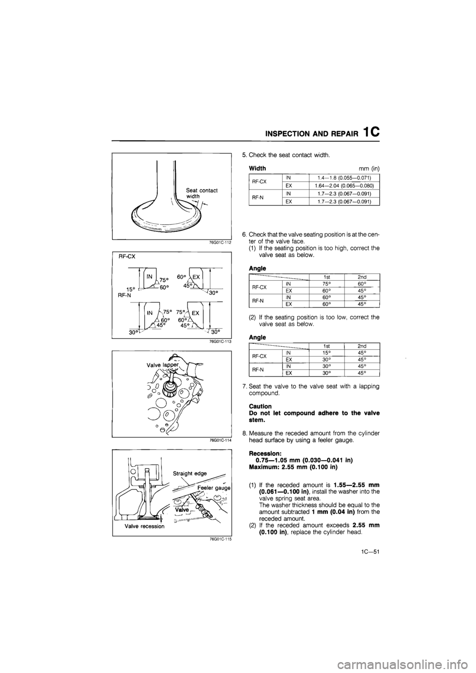
5. Check the seat contact width.
Width mm (in)
RF-CX IN 1.4-1.8 (0.055-0.071) RF-CX EX 1.64-2.04 (0.065-0.080)
RF-N IN 1.7—2.3 (0.067-0.091) RF-N EX 1.7—2.3 (0.067—0.091)
6, Check that the valve seating position is at the cen-
ter of the valve face.
(1) If the seating position is too high, correct the
valve seat as below.
Angle
- - • -1st 2nd
RF-CX IN 75° 60° RF-CX EX 60° 45°
RF-N IN 60° 45° RF-N EX 60° 45°
(2) If the seating position is too low, correct the
valve seat as below.
Angle
1st 2nd
RF-CX IN 15° 45° RF-CX EX 30° 45°
RF-N IN 30° 45° RF-N EX 30° 45°
7. Seat the valve to the valve seat with a lapping
compound.
Caution
Do not let compound adhere to the valve
stem.
8. Measure the receded amount from the cylinder
head surface by using a feeler gauge.
Recession-
0.75—1.05 mm (0.030—0.041 in)
Maximum: 2.55 mm (0.100 in)
(1) If the receded amount is 1.55—2.55 mm
(0.061—0.100 in), install the washer into the
valve spring seat area.
The washer thickness should be equal to the
amount subtracted 1 mm (0.04 in) from the
receded amount.
(2) If the receded amount exceeds 2.55 mm
(0.100 in), replace the cylinder head.
76G01C-144
1C-51
Page 277 of 1865

ASSEMBLY (CYLINDER BLOCK) 1 C
Cylinder block side Crankshaft side
Lower side
4BG01B-159
2. Apply engine oil to the main bearings and main
journals.
3. Install the crankshaft and bearings.
4. Install the main bearing cap according to the cap
number and mark, and tighten it evenly in or-
der shown in the figure.
5. Check that the crankshaft turns easily.
76G01C-153
6. Inspect the crankshaft end play.
End play:
0.040—0.282 mm (0.0016—0.0111 in)
Maximum: 0.30 mm (0.012 in)
76G01C-154
76G01C-155
7. If the end play is not within the specification, ad-
just the end play with an oversize thrust bearing.
Standard width:
2.00—2.05 mm (0.0787—0.0807 in)
Oversize width:
2.175—2.225 mm (0.0856—0.0876 in)
Note
First replace the rear thrust bearings, if still
not within the specification, replace the front
thrust bearings also.
1C-65
Page 327 of 1865
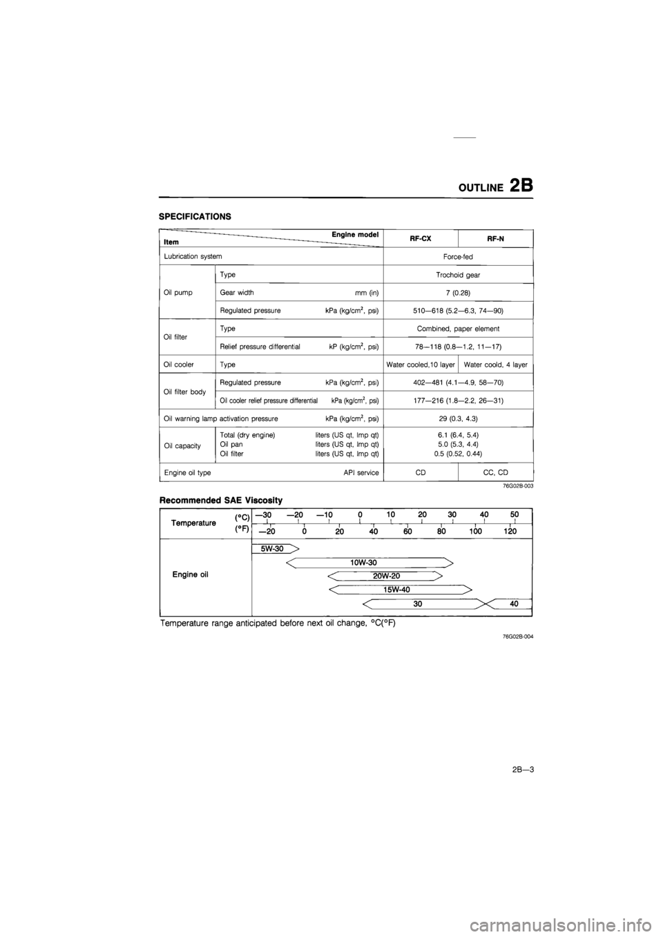
OUTLINE 2B
SPECIFICATIONS
Item Engine model RF-CX RF-N
Lubrication system Force-fed
Type Trochoid gear
Oil pump Gear width mm (in) 7 (0.28)
Regulated pressure kPa (kg/cm2,
psi)
510-618 (5.2 -6.3, 74—90)
Oil filter
Type Combined, paper element
Oil filter
Relief pressure differential kP (kg/cm2,
psi)
78-118 (0.8--1.2, 11-17)
Oil cooler Type Water cooled, 10 layer Water coold,
4
layer
Oil filter body
Regulated pressure kPa (kg/cm2,
psi)
402—481
(4.1
-4.9, 58—70)
Oil filter body
Oil cooler relief pressure differential kPa (kg/cm2, psi) 177-216 (1.8 -2.2, 26-31)
Oil warning lamp activation pressure kPa (kg/cm2,
psi)
29 (0.3, 4.3)
Oil capacity
Total (dry engine)
Oil pan
Oil filter
liters (US qt, Imp
qt)
liters (US qt, Imp
qt)
liters (US qt, Imp
qt)
6.1 (6.4, 5.4)
5.0 (5.3, 4.4)
0.5 (0.52, 0.44)
Engine oil type API service CD CC,
CD
76G02B-003
Recommended SAE Viscosity
CC) Temperature
—30 —20 —10 0 10 20 30 40 50 i i i i i i i ii CC) Temperature i i II i i i i —20 0 20 40 60 80 100 120
Engine oil
5W-30 >
Engine oil
< 10W-30 >
< 20W-20 >
< 15W-40 >
Engine oil
Temperature range anticipated before next oil change, °C(°F)
76G02B-004
2B-3
Page 1396 of 1865
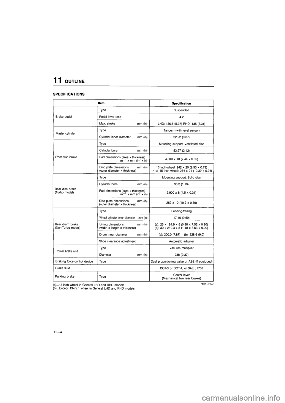
1 1 OUTLINE
SPECIFICATIONS
Item Specification
Brake pedal
Type Suspended
Brake pedal Pedal lever ratio 4.2 Brake pedal
Max. stroke mm (in) LHD: 136.5 (5.37) RHD: 135 (5.31)
Master cylinder Type Tandem (with level sensor) Master cylinder
Cylinder inner diameter mm (in) 22.22 (0.87)
Front disc brake
Type Mounting support, Ventilated disc
Front disc brake
Cylinder bore mm (in) 53.97 (2.12)
Front disc brake Pad dimensions (area x thickness) mm2 x mm (in2 x in) 4,800 x 10 (7.44 x 0.39) Front disc brake
Disc plate dimensions mm (in) (outer diameter x thickness) 13 inch-wheel: 242 x 20 (9.53 x 0.79) 14 or 15 inch-wheel: 264 x 24 (10.39 x 0.94)
Rear disc brake
(Turbo model)
Type Mounting support, Solid disc
Rear disc brake
(Turbo model)
Cylinder bore mm (in) 30.2 (1.19)
Rear disc brake
(Turbo model) Pad dimensions (area x thickness) mm2 x mm (in2 x in) 2,900 x 8 (4.5 x 0.31)
Rear disc brake
(Turbo model)
Disc plate dimensions mm (in) (outer diameter x thickness) 259 x 10 (10.2 x 0.39)
Rear drum brake
(Non-Turbo model)
Type Leading-trailing
Rear drum brake
(Non-Turbo model)
Wheel cylinder inner diameter mm (in) 17.46 (0.69)
Rear drum brake
(Non-Turbo model) Lining dimensions mm (in)
(width x length x thickness) (a): 25 x 191.9 x 5 (0.98 x 7.56 x 0.20)
(b): 30 x 219.3 x 5 (1.18 x 8.63 x 0.20)
Rear drum brake
(Non-Turbo model)
Drum inner diameter mm (in) (a): 200.0 (7.87) (b): 228.6 (9.0)
Rear drum brake
(Non-Turbo model)
Shoe clearance adjustment Automatic adjuster
Power brake unit Type Vacuum multiplier Power brake unit
Diameter mm (in) 238 (9.37)
Braking force control device Type Dual proportioning valve or ABS (if equipped)
Brake fluid DOT-3 or DOT-4, or SAE J1703
Parking brake Type Center lever (Mechanical two rear brakes)
(a)...13-inch wheel in General LHD and RHD models
(b)...Except 13-inch wheel in General LHD and RHD models
11-4