1987 MAZDA 626 width
[x] Cancel search: widthPage 1682 of 1865
![MAZDA 626 1987 Workshop Manual
METER 15
86U15X-033
86U15X-034
104.1t! 21
2330 16.10
a £] U \JEMP j n
JJ
86U15X-035
Standard indication
(km/h)
Allowable range
(km/h)
60 60-63
Standard indication
(mph)
Allowable ran MAZDA 626 1987 Workshop Manual
METER 15
86U15X-033
86U15X-034
104.1t! 21
2330 16.10
a £] U \JEMP j n
JJ
86U15X-035
Standard indication
(km/h)
Allowable range
(km/h)
60 60-63
Standard indication
(mph)
Allowable ran](/manual-img/28/57059/w960_57059-1681.png)
METER 15
86U15X-033
86U15X-034
104.1t! 21
2330 16.10
a £] U \JEMP j n
JJ
86U15X-035
Standard indication
(km/h)
Allowable range
(km/h)
60 60-63
Standard indication
(mph)
Allowable range
(mph)
60 60-63
86U15X-036
3. Set the SST to the resistance values shown in the
figure.
4. Turn the ignition switch ON, and check that the
needle indicator displays the correct values.
If the needle displays correctly, check the gauge
unit. If not, replace the fuel gauge in the meter or
repair the wiring harness.
Caution
a) Continue the above checks for at least two
minutes each to correctly judge the con-
dition.
b)The allowable indication error is twice the
width of the needle.
Water Temperature Gauge
1. Disconnect the connector from the water thermo
sensor.
2. Connect the red lead of the SST to the connec-
tor, and the black lead to a body ground.
3. Set the SST to the resistance values shown in the
figure.
4. Turn the ignition switch ON, and check that the
needle indicator displays the correct values.
If the needle displays the correct values, the trou-
ble is in the gauge unit; if not, the trouble is in the
meter or the wiring harness.
Caution
a) Continue the above checks for at least two
minutes each to correctly judge the con-
dition.
b)The allowable indication error is twice the
width of the needle.
INSPECTION OF DIGITAL METER
Speedometer
1. Using a speedometer tester, check the speedom-
eter for allowable indication error, and check the
operation of the odometer. Replace the meter as-
sembly if necessary.
2. Check the speedometer for fluctuation and/or ab-
normal noise.
Caution
a) If significant fluctuation occurs or the
speedometer does not move at all, remove
the speedometer cable. If normal, replace
the digital meter assembly.
b)Tire wear and improper inflation will in-
crease speedometer error.
15—27
Page 1816 of 1865
30 TECHNICAL DATA
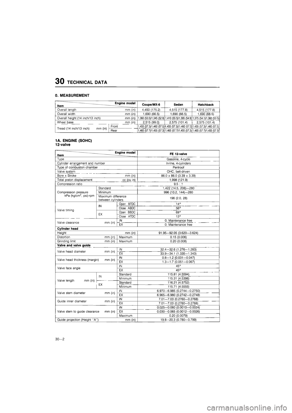
0. MEASUREMENT
Item Engine model Coupe/MX-6 Sedan Hatchback
Overall length mm (in) 4,450 (175.2) 4,515 (177.8) 4,515 (177.8)
Overall width mm (in) 1,690 (66.5) 1,690 (66.5) 1,690 (66.5)
Overall height (14 inch/13 inch) mm (in) 1,360 (53.5)/1,345 (52.9) 1,410 (55 5)/1,395 (54.9) 1,375 (54.1)/1,360 (53 5)
Wheel base mm (in) 2,515 (99.0) 2,575 (101.4) 2,575 (101.4)
Tread (14 inch/13 inch)
mm (in)
Front 1,455 (57.3)/1,460 (57.5) 1,455 (57.3)/(1,460 (57.5) 1,455 (57.3)/1,460 (57.5) Tread (14 inch/13 inch)
mm (in)
Rear 1,465 (57.7)/1,455 (57.3) 1,465 (57.7)/1,455 (57.3) 1,465 (57 7)/1,455 (57 3)
1
A. ENGINE (SOHC)
12-valve
— Engine model Item FE 12-valve
~vpe
Gasoline, 4-cycle
Cylinder arrangement and number In-line, 4-cylinders
Type
of
combustion chamber Pentroof
Valve system OHC, belt-driven
Bore
x
Stroke
mm (in)
86.0
x
86.0 (3.39
x
3.39)
Total piston displacement
cc
(cu
in)
1,998 (121.9)
Compression ratio 9.5
: 1
Compression pressure
kPa (kg/cm2, psi)-rpm
Standard 1,422 (14.5, 206)—280
Compression pressure
kPa (kg/cm2, psi)-rpm
Minimum 996 (10.2, 144)—280 Compression pressure
kPa (kg/cm2, psi)-rpm Maximum difference
between cylinders 196 (2.0,
28)
Valve timing
IN
Open
BTDC 14°
Valve timing
IN Close ABDC 56° Valve timing
EX Open BBDC 69° Valve timing
EX Close ATDC 13°
Valve clearance
mm (in)
IN 0; Maintenance free Valve clearance
mm (in)
EX 0; Maintenance free
Cylinder head
Heiaht
mm (inl
91.95-92.05 (3.620-3.624)
Distortion
mm (inl
Maximum 0.15 (0.006)
Grinding limit
mm (in)
Maximum 0.20 (0.008)
Valve and valve auide
Valve head diameter
mm (in)
IN 32.4-32.6 (1.276—1.283) Valve head diameter
mm (in)
EX 33.9-34.1 (1.335-1.343)
Valve head thickness (margin)
mm (in)
IN 0.8-1.2 (0.031—0.0471 Valve head thickness (margin)
mm (in)
EX 1.3—1.7 (0.051-0.067)
Valve face angle IN 45° Valve face angle EX 45°
Valve length
mm (in)
IN Standard 115.81 (4.55941
Valve length
mm (in)
IN Minimum 115.31 (4.5398) Valve length
mm (in)
cv Standard 116.21 (4.5752)
Minimum 115.71 (4.55551
Valve stem diameter
mm (in)
IN 6.970-6.985 (0.2744-0.2750) Valve stem diameter
mm (in)
EX 6.965-6.980 (0.2742-0.27481
Guide inner diameter
mm (in)
IN 7.01-7.03 (0,2760-0.2768) Guide inner diameter
mm (in)
EX 7.01-7.03 (0.2760-0.27681
Valve stem
to
guide clearance
mm (in)
IN 0.025-0.060 (0.0010-0.0024)
Valve stem
to
guide clearance
mm (in)
EX 0.030-0.065 (0.0012—0.0026) Valve stem
to
guide clearance
mm (in)
Maximum 0.20 (0.00791
Guide projection (Height "A")
mm (in)
19.8-20.3 (0.780-0.799)
30—2
Page 1817 of 1865
TECHNICAL DATA 30
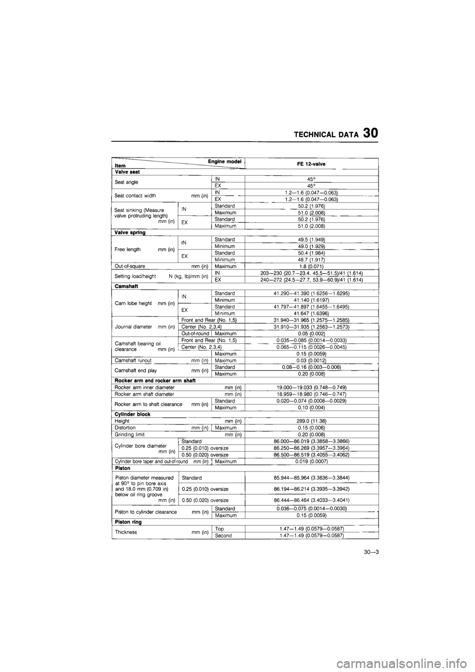
FE 12-valve Item FE 12-valve
Valve seat
Seat angle IN 45° Seat angle EX 45°
Seat contact width mm (in) IN 1.2-1.6 (0.047-0.063) Seat contact width mm (in) EX 1.2-1.6 (0.047-0.063)
Seat sinking (Measure valve protruding length) mm (in)
IN Standard 50.2 (1.976) Seat sinking (Measure valve protruding length) mm (in)
IN Maximum 51.0 (2.008) Seat sinking (Measure valve protruding length) mm (in) EX Standard 50.2 (1.976)
Seat sinking (Measure valve protruding length) mm (in) EX Maximum 51.0 (2.008)
Valve spring
IN Standard 49.5 (1.949)
Free length
mm
(in)
IN Minimum 49.0 (1.929) Free length
mm
(in)
EX Standard 50.4 (1.984) EX Minimum 48.7 (1.917)
Out-of-square mm (in) Maximum 1.8 (0.071)
Setting load/height
N
(kg, lb)/mm (in) IN 203-230 (20.7-23.4, 45.5-51,5)/41 (1.614) Setting load/height
N
(kg, lb)/mm (in) EX 240-272 (24.5—27.7, 53.9-60.9)/41 (1.614)
Camshaft
IN Standard 41.290-41.390 (1.6256-1.6295)
Cam lobe height
mm
(in)
IN Minimum 41.140 (1.6197) Cam lobe height
mm
(in)
EX Standard 41.797-41.897 (1.6455—1.6495) EX Minimum 41.647 (1.6396)
Front and Rear (No.
1,5)
31.940-31.965 (1.2575-1.2585)
Journal diameter
mm (in)
Center (No. 2,3,4) 31.910-31.935 (1.2563-1.2573)
Out-of-round Maximum 0.05 (0.002)
Camshaft bearing
oil
clearance
mm
(in)
Front and Rear (No.
1,5)
0.035—0.085 (0.0014-0.0033) Camshaft bearing
oil
clearance
mm
(in) Center (No. 2,3,4) 0.065-0.115 (0.0026-0.0045) Camshaft bearing
oil
clearance
mm
(in) Maximum 0.15 (0.0059)
Camshaft runout mm (in) Maximum 0.03 (0.0012)
Camshaft end play mm (in) Standard 0.08-0.16 (0.003—0.0061 Camshaft end play mm (in) Maximum 0.20 (0.008)
Rocker arm and rocker arm shaft
Rocker arm inner diameter mm (in) 19.000—19.033 (0.748—0.749)
Rocker arm shaft diameter mm (in) 18.959-18.980 (0.746-0.747)
Rocker arm
to
shaft clearance mm (in) Standard 0.020-0.074 (0.0008-0.0029) Rocker arm
to
shaft clearance mm (in) Maximum 0.10 (0.004)
Cylinder block
Height mm (in) 289.0 (11.38)
Distortion mm (in) Maximum 0.15 (0.006)
Grinding limit mm (in) 0.20 (0.008)
Cylinder bore diameter
mm (in)
Standard 86.000—86.019 (3.3858-3.3866) Cylinder bore diameter
mm (in) 0.25 (0.010) oversize 86.250-86.269 (3.3957-3.3964) Cylinder bore diameter
mm (in) 0.50 (0.020) oversize 86.500-86.519 (3.4055-3.4062)
Cylinder bore taper and out-of-round mm (in) Maximum 0.019 (0.0007)
Piston
Piston diameter measured at 90°
to
pin bore axis and 18.0 mm (0.709
in)
below oil ring groove
mm (in)
Standard 85.944-85.964 (3.3836-3.3844) Piston diameter measured at 90°
to
pin bore axis and 18.0 mm (0.709
in)
below oil ring groove
mm (in)
0.25 (0.010) oversize 86.194-86.214 (3.3935—3.3942)
Piston diameter measured at 90°
to
pin bore axis and 18.0 mm (0.709
in)
below oil ring groove
mm (in) 0.50 (0.020) oversize 86.444-86.464 (3.4033—3.4041)
Piston
to
cylinder clearance mm (in) Standard 0.036-0.075 (0.0014-0.0030) Piston
to
cylinder clearance mm (in) Maximum 0.15 (0.0059)
Piston ring
Thickness mm (in)
TOD
1.47-1.49 (0.0579—0.05871 Thickness mm (in) Second 1.47-1.49 (0.0579-0.0587)
30-3
Page 1818 of 1865
30 TECHNICAL DATA
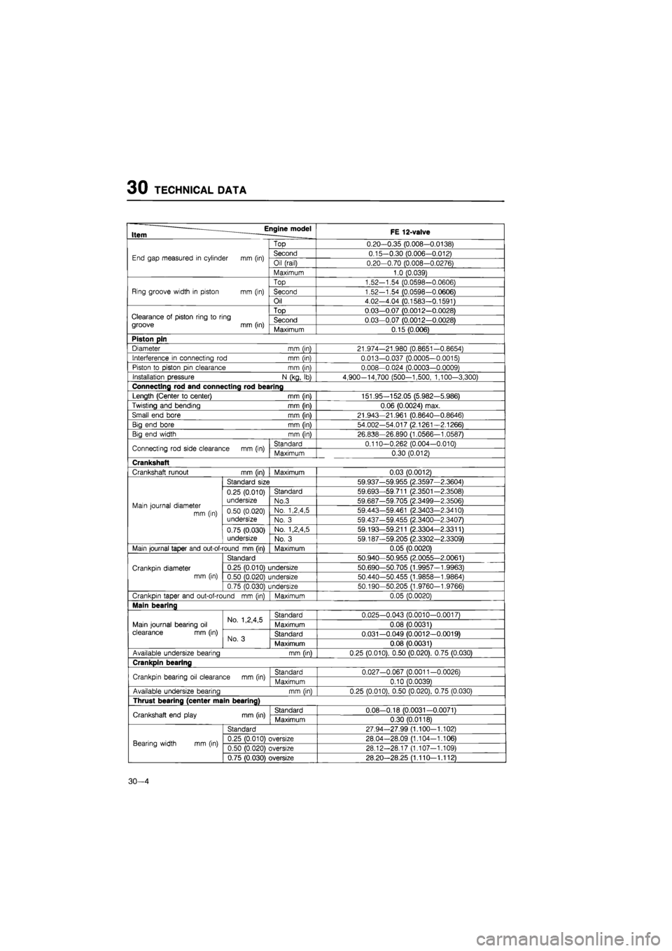
Item Engine model FE 12-valve
Top 0.20—0.35 (0.008-0.0138)
End gap measured
in
cylinder
mm
(in) Second 0.15—0.30 (0.006-0.012) End gap measured
in
cylinder
mm
(in) Oil (rail) 0.20-0.70 (0.008-0.0276)
Maximum 1.0 (0.039)
Top 1.52-1.54 (0.0598-0.0606)
Ring groove width
in
piston mm (in) Second 1.52-1.54 (0.0598-0.0606)
Oil 4.02-4.04 (0.1583-0.1591)
Top 0.03—0.07 (0.0012—0.0028) Clearance
ot
piston ring
to
ring Second 0.03—0.07 (0.0012-0.0028)
Maximum 0.15(0.006)
Piston pin
Diameter mm (in) 21.974-21.980 (0.8651-0.8654)
Interference
in
connecting
rod
mm (in) 0.013-0.037 (0.0005-0.0015)
Piston
to
piston pin clearance mm (in) 0.008-0.024 (0.0003—0.0009)
Installation pressure N (kg,
lb)
4,900-14,700 (500-1,500, 1,100-3,300)
Connecting rod and connecting rod bearing
Length (Center
to
center) mm (in) 151.95—152.05 (5.982—5.986)
Twisting and bending mm (in) 0.06 (0.0024) max.
Small end bore mm (in) 21.943—21.961 (0.8640-0.8646)
Big end bore mm (in) 54.002-54.017 (2.1261—2.1266)
Big end width mm (in) 26.838-26.890 (1.0566—1.0587)
Connecting rod side clearance
mm
(in) Standard 0.110-0.262 (0.004-0.010) Connecting rod side clearance
mm
(in) Maximum 0.30 (0.012)
Crankshaft
Crankshaft runout mm (in) Maximum 0.03 (0.0012)
Standard size 59.937-59.955 (2.3597—2.3604)
0.25 (0.010) Standard 59.693-59.711 (2.3501-2.3508)
Main journal diameter mm (in)
undersize No.3 59.687-59.705 (2.3499-2.3506) Main journal diameter mm (in) 0.50 (0.020) No. 1,2,4,5 59.443-59.461 (2.3403-2.3410) Main journal diameter mm (in) undersize No.
3
59.437-59.455 (2.3400-2.3407)
0.75 (0.030) No. 1,2,4,5 59.193-59.211 (2.3304-2.3311)
undersize No.
3
59.187-59.205 (2.3302-2.3309)
Main journal taper and out-of-round mm (in) Maximum 0.05 (0.0020)
Standard 50.940-50.955 (2.0055-2.0061)
Crankpin diameter 0.25 (0.010) undersize 50.690—50.705 (1.9957-1.9963)
mm (in) 0.50 (0.020) undersize 50.440-50.455 (1.9858-1.9864)
0.75 (0.030) undersize 50.190-50.205 (1.9760-1.9766)
Crankpin taper and out-of-round
mm (in)
Maximum 0.05 (0.0020)
Main bearing
No. 1,2,4,5 Standard 0.025-0.043 (0.0010—0.0017)
Main journal bearing
oil
No. 1,2,4,5 Maximum 0.08 (0.0031) clearance
mm
(in) No.
3
Standard 0.031—0.049 (0.0012—0.0019) No.
3
Maximum 0.08 (0.0031)
Available undersize bearing mm fin} 0.25 (0.010), 0.50 (0.020), 0.75 (0.030)
Crankpin bearing
Crankpin bearing
oil
clearance
mm
(in) Standard 0.027-0.067 (0.0011-0.0026) Crankpin bearing
oil
clearance
mm
(in) Maximum 0.10 (0.0039)
Available undersize bearina mm (in) 0.25 (0.010), 0.50 (0.020), 0.75 (0.030)
Thrust bearing (center main bearing)
Crankshaft end play mm (in) Standard 0.08-0.18 (0.0031-0.0071) Crankshaft end play mm (in) Maximum 0.30 (0.0118)
Standard 27.94-27.99 (1.100-1.102)
Bearing width
mm (in)
0.25 (0.010) oversize 28.04-28.09 (1.104-1.106) Bearing width
mm (in)
0.50 (0.020) oversize 28.12-28.17 (1.107-1.109)
0.75 (0.030) oversize 28.20—28.25 (1.110—1.112)
30—4
Page 1820 of 1865
30 TECHNICAL DATA
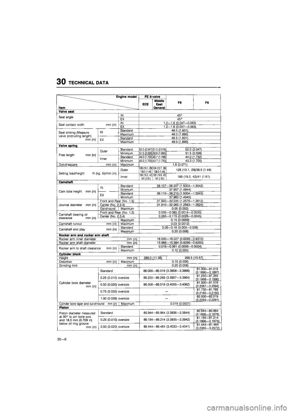
Engine model FE 8-valve
Item ECE Middle East General
F8 F6
Valve seat
Seat angle IN 45° Seat angle EX 45°
Seat contact width mm (in) IN 1.2—1.6 (0.047-0.063) Seat contact width mm (in) EX 1.2-1.6 (0.047-0.063)
Seat sinking (Measure valve protruding length)
mm (in)
IN Standard 46.5 (1.831) Seat sinking (Measure valve protruding length)
mm (in)
IN Maximum 48.0 (1.890) Seat sinking (Measure valve protruding length)
mm (in) EX Standard 46.5 (1.831)
Seat sinking (Measure valve protruding length)
mm (in) EX Maximum 48.0 (1.890)
Valve spring
Free length mm (in)
Outer
Inner
Standard
Minimum
51.5(2.028)
Standard
44.0 (1.732)
Minimum
43.3 (1.705)
51.2 (2.016)
52.0 (2.047)
50.6 (1.992)
51.5 (2.028)
45.7 (1.799)
44.0 (1.732)
437 (1.720)1
43.3 (1.705)
Out-of-square mm (in) Maximum 1.8 (0.071)
Setting load/height
N
(kg, lb)/mm
(in)
Outer
128(13.1,29) 136.5
(1
44)
Inner
189 (19,2, 42) 141 (1.61)
124 (12.7, 28) 136.5
(1
44)
193 (19.6,43) 141 (1.61)
128 (13.1, 29)/36.5 (1.44)
189 (19.2, 42)/41 (1.61)
Camshaft
Cam lobe height
mm (in)
IN
EX
Standard
Minimum
Standard
Minimum
38.107-38.207 (1.5003-1.5042)
37.957 (1.4944)
38.110-38.210 (1.5004-1.5043)
37.960 (1.4945)
Journal diameter
mm (in)
Front and Rear (No.
1,5)
31.940-32.035 (1.2575-1.2612)
Center (No. 2,3,4)
Out-of-round Maximum
31.910-32.065 (1.2563-1.2624)
0.05 (0.002)
Camshaft bearing
oil
clearance
mm (in)
Front and Rear (No.
1,5)
0.035-0.085 (0.0014-0.00331
Center (No. 2,3,4) 0.065-0.115 (0.0026—0.0045)
Maximum 0.15 (0.0059)
Camshaft runout mm (in) Maximum 0.03 (0.00121
Camshaft end play mm (in) Standard 0.08—0.16 (0.003—0.006)
Maximum 0.20 (0.008)
Rocker arm and rocker arm shaft
Rocker arm inner diameter mm (in) 16.000-16.027 (0.6299-0.6310)
Rocker arm shaft diameter mm (in) 15.966-15.984 (0.6286-0.6293)
Rocker arm
to
shaft clearance
mm (in)
Standard 0.016—0.061 (0.0006-0.0024)
Maximum 0.10 (0.004)
Cylinder block
Heiaht mm
fin)
289.0 (11.38) 268.5 (10.57)
Distortion mm (in) Maximum 0.15 (0.006)
Grindina limit mm (in)
0.20 (0.008)
Cylinder bore diameter
mm (in)
Standard 86.000—86.019 (3.3858—3.3866)
0.25 (0.010) oversize 86.250-86.269 (3.3957-3.3964)
0.50 (0.020) oversize 86.500-86.519 (3.4055-3.4062)
0.75 (0.030) oversize
1.00 (0.039) oversize
81.000-
(3.1890-
-81.019 -3.1897)
81.250-(3.1988-
-81.269
-3.1996) 81.500-(3.2087-
-81.519 -3.2094)
81.750-(3.2185-
-81.769
-3.2192)
82.000-
(3.2283-
-82.019
-3.2291)
Cylinder bore taper and out-of-round mm (in) Maximum 0.019 (0.0007)
Piston
Piston diameter measured at 90°
to pin
bore axis and 18.0
mm
(0.709
in)
below
oil
ring groove
mm (in)
Standard 85.944-85.964 (3.3836—3.3844) 80.944-80.964
(3.1868—3.1876) Piston diameter measured at 90°
to pin
bore axis and 18.0
mm
(0.709
in)
below
oil
ring groove
mm (in)
0.25 (0.010) oversize 86.194—86.214 (3.3935—3.3942) 81.194—81.214
(3.1966-3.1974)
Piston diameter measured at 90°
to pin
bore axis and 18.0
mm
(0.709
in)
below
oil
ring groove
mm (in) 0.50 (0.020) oversize 86.444-86.464 (3.4033-3.4041) 81.444-81.464
(3.2065-3.2072)
30—6
Page 1821 of 1865
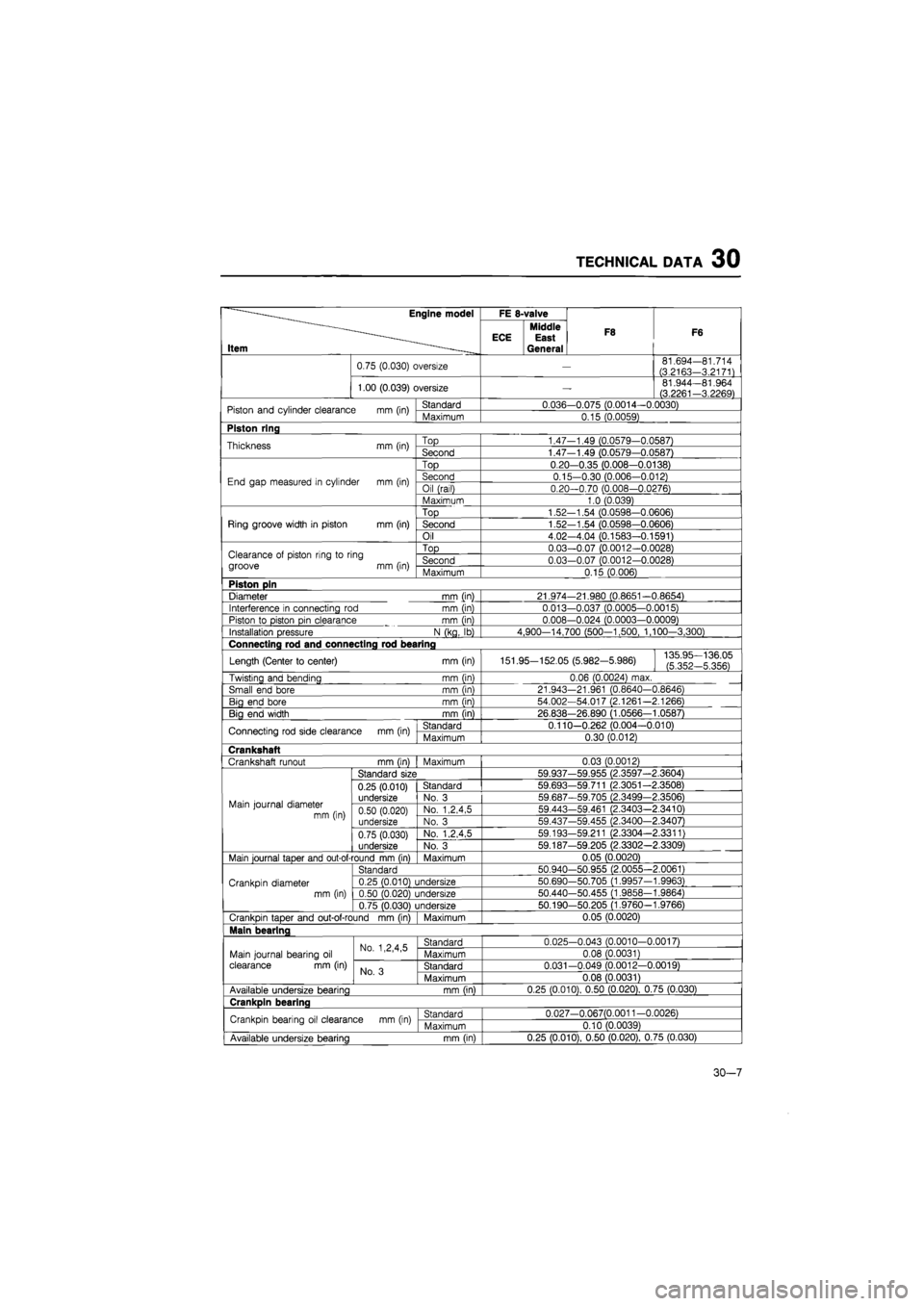
TECHNICAL DATA 30
—Engine model
Item -
FE 8-valve
F8 F6
—Engine model
Item -
ECE Middle East General
F8 F6
0.75 (0.030) oversize
—
81.694—81.714
(3.2163-3.2171)
1.00 (0.039) oversize
—
81.944—81.964 (3.2261-3.2269)
Piston and cylinder clearance
mm
(in) Standard 0.036-0.075 (0.0014—0.0030) Piston and cylinder clearance
mm
(in) Maximum 0.15 (0.0059)
Piston ring
Thickness
mm
(in) Top 1.47-1.49 (0.0579-0.0587) Thickness
mm
(in) Second 1.47-1.49 (0.0579—0.0587)
End gap measured
in
cylinder
mm (in)
Top 0.20—0.35 (0.008—0.0138)
End gap measured
in
cylinder
mm (in)
Second 0.15-0.30 (0.006-0.012) End gap measured
in
cylinder
mm (in)
Oil (rail) 0.20—0.70 (0.008—0.0276) End gap measured
in
cylinder
mm (in)
Maximum 1.0 (0.039)
Ring groove width
in
piston
mm
(in)
Top 1.52—1.54 (0.0598-0.0606)
Ring groove width
in
piston
mm
(in) Second 1.52-1.54 (0.0598-0.0606) Ring groove width
in
piston
mm
(in)
Oil 4.02-4.04 (0.1583-0.1591)
Clearance
of
piston ring
to
ring
groove
mm
(in)
Top 0.03-0.07 (0.0012-0.0028) Clearance
of
piston ring
to
ring
groove
mm
(in) Second 0.03-0.07 (0.0012-0.0028) Clearance
of
piston ring
to
ring
groove
mm
(in) Maximum 0.15 (0.006)
Piston pin
Diameter
mm
(in) 21.974—21.980 (0.8651—0.8654)
Interference
in
connecting
rod mm
(in) 0.013—0.037 (0.0005—0.0015)
Piston
to
piston pin clearance
mm
(in) 0.008—0.024 (0.0003-0.0009)
Installation pressure
N
(kg,
lb)
4,900—14,700 (500—1,500, 1,100—3,300)
Connecting rod and connecting rod bearing
Length (Center
to
center)
mm
(in) 151.95-152.05 (5.982-5.986) 135.95—136.05
(5.352-5.356)
Twisting and bending
mm
(in) 0.06 (0.0024) max.
Small end bore
mm
(in) 21.943-21.961 (0.8640-0.8646)
Big end bore
mm
(in) 54.002-54.017 (2.1261—2.1266)
Bia end width
mm
(in) 26.838-26.890 (1.0566—1.0587)
Connecting rod side clearance
mm
(in) Standard 0.110-0.262 (0.004—0.010) Connecting rod side clearance
mm
(in) Maximum 0.30 (0.012)
Crankshaft
Crankshaft runout mm (in)
I
Maximum 0.03 (0.0012)
Main journal diameter
mm (in)
Standard size 59.937-59.955 (2.3597—2.3604)
Main journal diameter
mm (in)
0.25 (0.010) undersize
Standard 59.693—59.711 (2.3051—2.3508)
Main journal diameter
mm (in)
0.25 (0.010) undersize No.
3
59.687—59.705 (2.3499-2.3506) Main journal diameter
mm (in) 0.50 (0.020) undersize
No. 1,2,4,5 59.443-59.461 (2.3403—2.3410) Main journal diameter
mm (in) 0.50 (0.020) undersize No.
3
59.437-59.455 (2.3400—2.3407)
Main journal diameter
mm (in)
0.75 (0.030)
undersize
No. 1,2,4,5 59.193-59.211 (2.3304—2.3311)
Main journal diameter
mm (in)
0.75 (0.030)
undersize No.
3
59.187—59.205 (2.3302—2.3309)
Main journal taper and out-of-round mm (in) Maximum 0.05 (0.0020)
Crankpin diameter mm (in)
Standard 50.940-50.955 (2.0055-2.0061)
Crankpin diameter mm (in)
0.25 (0.010) undersize 50.690-50.705 (1.9957-1.9963) Crankpin diameter mm (in) 0.50 (0.020) undersize 50.440-50.455 (1.9858-1.9864) Crankpin diameter mm (in)
0.75 (0.030) undersize 50.190—50.205 (1.9760-1.9766)
Crankpin taper and out-of-round
mm
(in) Maximum 0.05 (0.0020)
Main bearlna
Main journal bearing
oil
clearance
mm
(in)
No. 1,2,4,5 Standard 0.025-0.043 (0.0010-0.0017)
Main journal bearing
oil
clearance
mm
(in)
No. 1,2,4,5 Maximum 0.08 (0.0031) Main journal bearing
oil
clearance
mm
(in) No.
3
Standard 0.031—0.049 (0.0012—0.0019)
Main journal bearing
oil
clearance
mm
(in) No.
3
Maximum 0.08 (0.0031)
Available undersize bearina
mm
(in) 0.25 (0.010), 0.50 (0.020), 0.75 (0.030)
Crankpin bearing
Crankpin bearing
oil
clearance
mm
(in) Standard 0.027-0.067(0.0011 -0.0026) Crankpin bearing
oil
clearance
mm
(in) Maximum 0.10 (0.0039)
Available undersize bearing
mm
(in) 0.25 (0.010), 0.50 (0.020), 0.75 (0.030)
30-7
Page 1822 of 1865
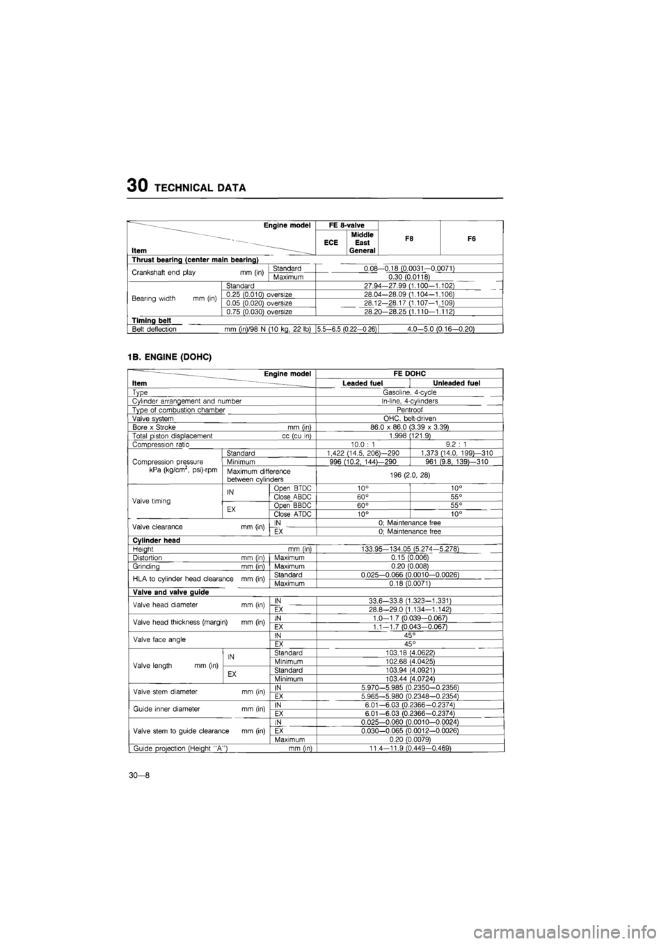
30 TECHNICAL DATA
~ ——Engine model
Item —
FE 8-valve
F8 F6
~ ——Engine model
Item —
Middle ECE East General
F8 F6
Thrust bearing (center main bearing)
Crankshaft end play
mm
(in) Standard 0.08-0.18 (0.0031-0.0071) Crankshaft end play
mm
(in) Maximum 0.30 (0.0118)
Bearing width
mm (in)
Standard 27.94-27.99 (1.100-1.102)
Bearing width
mm (in)
0.25 (0.010) oversize 28.04—28.09 (1.104-1.106) Bearing width
mm (in)
0.05 (0.020) oversize 28.12-28.17 (1.107-1.109) Bearing width
mm (in)
0.75 (0.030) oversize 28.20—28.25 (1.110—1.112)
Timing belt
Belt deflection
mm
(in)/98
N
(10 kg,
22 lb)
|5.5—6.5 (0.22-0 26) 4.0-5.0 (0.16-0.20)
1B. ENGINE (DOHC)
— Engine model FE DOHC
Item ~ Leaded fuel Unleaded fuel
Type Gasoline, 4-cycle
Cylinder arrangement and number In-line, 4-cylinders
Type
of
combustion chamber Pentroof
Valve system OHC. belt-driven
Bore
x
Stroke mm (in) 86.0
x
86.0 (3.39
x
3.39)
Total piston displacement cc (cu
in)
1,998 (121.9)
Compression ratio 10.0
: 1
9.2
: 1
Standard 1,422 (14.5, 206)—290 1,373 (14.0, 199)—310
Compression pressure Minimum 996 (10.2, 144)—290 961 (9.8, 139)—310
kPa (kg/cm2, psi)-rpm Maximum difference
between cylinders 196 (2.0, 28)
IN Open BTDC 10° 10°
Valve timing
IN Close ABDC 60° 55° Valve timing
EX Open BBDC 60° 55° EX Close ATDC 10° 10°
Valve clearance mm (in) IN 0; Maintenance free Valve clearance mm (in) EX 0; Maintenance free
Cylinder head
Heiaht mm (in) 133.95-134.05 (5.274-5.278)
Distortion mm (in) Maximum 0.15 (0.006)
Grinding mm (in) Maximum 0.20 (0.008)
HLA
to
cylinder head clearance mm (in) Standard 0.025-0.066 (0.0010-0.0026) HLA
to
cylinder head clearance mm (in) Maximum 0.18 (0.0071)
Valve and valve guide
Valve head diameter mm (in) IN 33.6-33.8 (1.323-1.331) Valve head diameter mm (in) EX 28.8-29.0 (1.134—1.142)
Valve head thickness (margin)
mm
(in) IN 1.0-1.7 (0.039-0.067) Valve head thickness (margin)
mm
(in) EX 1.1—1.7 (0.043—0.067)
Valve face angle IN 45° Valve face angle EX 45°
IN Standard 103.18 (4.0622)
Valve length
mm (in)
IN Minimum 102.68 (4.0425) Valve length
mm (in)
EX Standard 103.94 (4.0921) EX Minimum 103.44 (4.0724)
Valve stem diameter mm (in) IN 5.970-5.985 (0.2350-0.2356) Valve stem diameter mm (in) EX 5.965-5.980 (0.2348—0.2354)
Guide inner diameter mm (in) IN 6.01-6.03 (0.2366-0.2374) Guide inner diameter mm (in) EX 6.01—6.03 (0.2366-0.2374)
IN 0.025-0.060 (0.0010-0.0024)
Valve stem
to
guide clearance mm (in) EX 0.030-0.065 (0.0012-0.0026)
Maximum 0.20 (0.0079)
| Guide projection (Height "A") mm (in) 11.4-11.9 (0.449-0.469)
30-8
Page 1823 of 1865
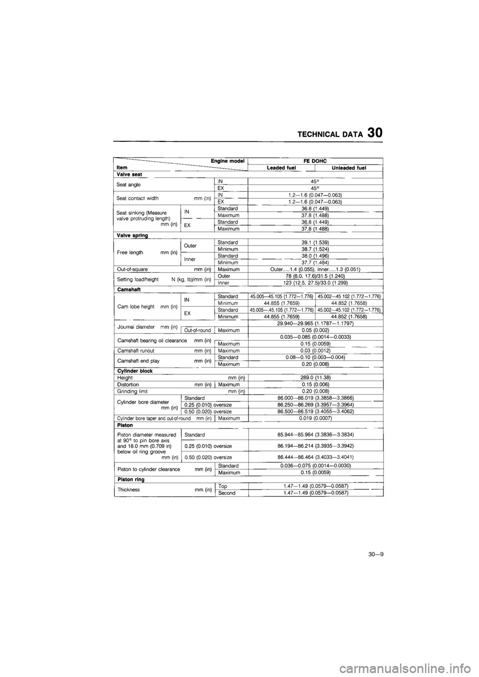
TECHNICAL DATA 30
——Engine model
Item -
FE DOHC ——Engine model
Item -Leaded fuel Unleaded fuel
Valve seat
Seat angle IN 45° Seat angle EX 45°
Seat contact width
mm
(in) IN 1.2-1.6 (0.047-0.063) Seat contact width
mm
(in) EX 1.2-1.6 (0.047-0.063)
Seat sinking (Measure valve protruding length) mm (in)
IN Standard 36.8 (1.449) Seat sinking (Measure valve protruding length) mm (in)
IN Maximum 37.8 (1.488) Seat sinking (Measure valve protruding length) mm (in) EX Standard 36.8 (1.449)
Seat sinking (Measure valve protruding length) mm (in) EX Maximum 37.8 (1.488)
Valve spring
Free length mm (in)
Outer Standard 39.1 (1.539)
Free length mm (in)
Outer Minimum 38.7 (1.524) Free length mm (in)
Inner Standard 38.0 (1.496) Free length mm (in)
Inner Minimum 37.7 (1.484)
Out-of-square
mm
(in) Maximum Outer 1.4 (0.055), Inner 1.3 (0.051)
Setting load/height
N
(kg, lb)/mm
(in)
Outer 78 (8.0, 17.6)/31.5 (1.240) Setting load/height
N
(kg, lb)/mm
(in)
Inner 123 (12.5, 27.5)/33.0 (1.299)
Camshaft
Cam lobe height
mm (in)
IN Standard 45.005-45.105 (1.772-1.776) 45.002-45 102 (1.772-1.776)
Cam lobe height
mm (in)
IN Minimum 44.855 (1.7659) 44.852 (1.7658) Cam lobe height
mm (in)
EX Standard 45.005—.45.105 (1.772-1.776) 45.002-45.102 (1.772-1.776) Cam lobe height
mm (in)
EX Minimum 44.855 (1.7659) 44.852 (1.7658)
Journal diameter
mm
(in) 29.940-29.965 (1.1787-1.1797) Journal diameter
mm
(in) Out-of-round
|
Maximum 0.05 (0.002)
Camshaft bearing
oil
clearance mm (in) 0.035-0.085 (0.0014-0.0033) Camshaft bearing
oil
clearance mm (in) Maximum 0.15 (0.0059)
Camshaft runout
mm (in)
Maximum 0.03 (0.0012)
Camshaft end play
mm
(in) Standard 0.08-0.10 (0.003-0.004) Camshaft end play
mm
(in) Maximum 0.20 (0.008)
Cylinder block
Height
mm
(in) 289.0 (11.38)
Distortion
mm
(in) Maximum 0.15 (0.006)
Grindino limit
mm
fin) 0.20 (0.008)
Cylinder bore diameter mm (in)
Standard 86.000—86.019 (3.3858-3.3866) Cylinder bore diameter mm (in) 0.25 (0.010) oversize 86.250—86.269 (3.3957—3.3964) Cylinder bore diameter mm (in) 0.50 (0.020) oversize 86.500-86.519 (3.4055-3.4062)
Cylinder bore taper and out-of-round mm (in) Maximum 0.019 (0.0007)
Piston
Piston diameter measured at 90°
to pin
bore axis and 18.0
mm
(0.709
in)
below oil ring groove
mm (in)
Standard 85.944-85.964 (3.3836-3.3834) Piston diameter measured at 90°
to pin
bore axis and 18.0
mm
(0.709
in)
below oil ring groove
mm (in)
0.25 (0.010) oversize 86.194-86.214 (3.3935-3.3942)
Piston diameter measured at 90°
to pin
bore axis and 18.0
mm
(0.709
in)
below oil ring groove
mm (in) 0.50 (0.020) oversize 86.444-86.464 (3.4033-3.4041)
Piston
to
cylinder clearance
mm
(in) Standard 0.036-0.075 (0.0014-0.0030) Piston
to
cylinder clearance
mm
(in) Maximum 0.15 (0.0059)
Piston ring
Thickness mm (in)
TOD
1.47-1.49 (0.0579-0.0587) Thickness mm (in) Second 1.47-1.49 (0.0579-0.0587)
30-9