Page 535 of 878
INSTALLATION HINT:
Use a new gasket (2JZ±GE) or O±ring (2JZ±GTE).
Torque:
2JZ±GE
49 NVm (500 kgfVcm, 36 ftVlbf)
2JZ±GTE
29 NVm (300 kgfVcm, 22 ftVlbf)
2. REMOVE DRIVE AND DRIVEN ROTORS
Remove the 10 screws, pump body cover, the drive and driv-
en rotors.
Torque: 10 NVm (105 kgfVcm, 8.0 ftVlbf)
ASSEMBLY HINT: Place the drive and driven rotors into the
oil pump body with the mark facing upward.
OIL PUMP INSPECTION
1. INSPECT RELIEF VALVE
Coat the valve with engine oil and check that it falls smoothly
into the valve hole under its own weight.
If it doesn't, replace the relief valve. If necessary, replace the
oil pump assembly.
2. INSPECT DRIVE AND DRIVEN ROTORS
A. Place drive and driven rotors into oil pump body
ASSEMBLY HINT: Place the drive and driven rotors into the
oil pump body with the mark facing upward.
± ENGINELUBRICATION SYSTEMEG±371
Page 542 of 878

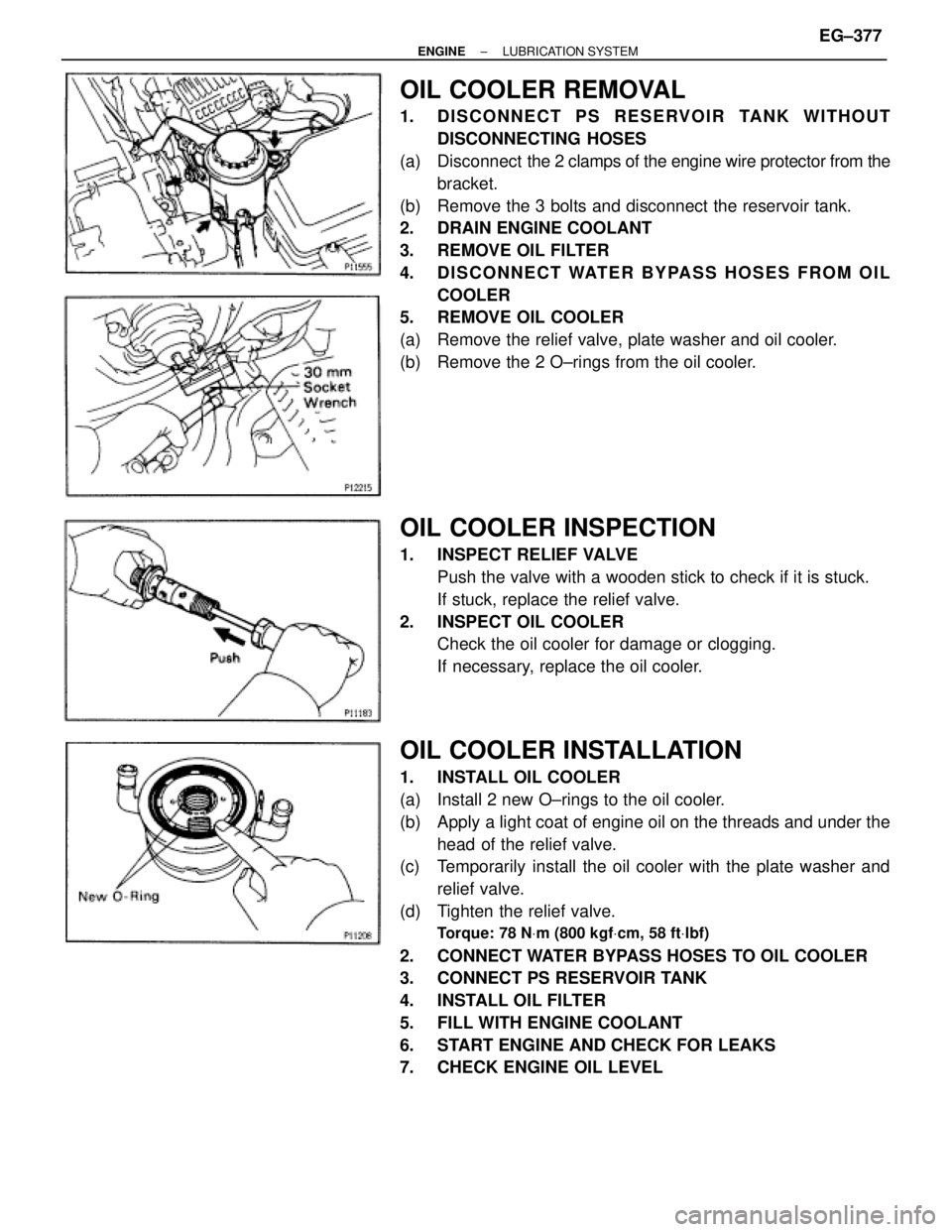
OIL COOLER REMOVAL
1. DISCONNECT PS RESERVOIR TANK WITHOUT
DISCONNECTING HOSES
(a) Disconnect the 2 clamps of the engine wire protector from the
bracket.
(b) Remove the 3 bolts and disconnect the reservoir tank.
2. DRAIN ENGINE COOLANT
3. REMOVE OIL FILTER
4. DISCONNECT WATER BYPASS HOSES FROM OIL
COOLER
5. REMOVE OIL COOLER
(a) Remove the relief valve, plate washer and oil cooler.
(b) Remove the 2 O±rings from the oil cooler.
OIL COOLER INSPECTION
1. INSPECT RELIEF VALVE
Push the valve with a wooden stick to check if it is stuck.
If stuck, replace the relief valve.
2. INSPECT OIL COOLER
Check the oil cooler for damage or clogging.
If necessary, replace the oil cooler.
OIL COOLER INSTALLATION
1. INSTALL OIL COOLER
(a) Install 2 new O±rings to the oil cooler.
(b) Apply a light coat of engine oil on the threads and under the
head of the relief valve.
(c) Temporarily install the oil cooler with the plate washer and
relief valve.
(d) Tighten the relief valve.
Torque: 78 NVm (800 kgfVcm, 58 ftVlbf)
2. CONNECT WATER BYPASS HOSES TO OIL COOLER
3. CONNECT PS RESERVOIR TANK
4. INSTALL OIL FILTER
5. FILL WITH ENGINE COOLANT
6. START ENGINE AND CHECK FOR LEAKS
7. CHECK ENGINE OIL LEVEL
± ENGINELUBRICATION SYSTEMEG±377
Page 543 of 878
OIL NOZZLE (2JZ±GTE)
COMPONENTS
OIL NOZZLES REMOVAL
1. REMOVE CRANKSHAFT
(See step 6 in cylinder block disassembly in Engine Me-
chanical)
2. REMOVE OIL NOZZLES (WITH RELIEF VALVES)
Using a 5 mm hexagon wrench, remove the bolt and oil
nozzle. Remove the 6 oil nozzles.
OIL NOZZLES INSPECTION
INSPECT RELIEF VALVES (OIL NOZZLES)
Push the valve with a wooden stick to check if it is stuck.
If stuck, replace the relief valve.
OIL NOZZLES INSTALLATION
1. INSTALL OIL NOZZLES (WITH RELIEF VALVES)
Using a 5 mm hexagon wrench, install the oil nozzle with the
bolt. Install the 6 oil nozzles.
Torque: 8.8 NVm (90 kgfVcm, 78 in.Vlbf)
2. INSTALL CRANKSHAFT
(See step 8 in cylinder block assembly in Engine Me-
chanical) EG±378
± ENGINELUBRICATION SYSTEM
Page 573 of 878
COOLANT CHECK
1. CHECK ENGINE COOLANT LEVEL AT RADIATOR
RESERVOIR
The engine coolant level should be between the ºLOWº and
ºFULLº lines.
If low, check for leaks and add engine coolant up to the
ºFULLº line.
2. CHECK ENGINE COOLANT QUALITY
(a) Remove the radiator cap.
CAUTION: To avoid the danger of being burned, do not remove
the radiator cap while the engine and radiator are still hot, as
fluid and steam can be blown out under pressure.
(b) There should not be any excessive deposits of rust or scale
around the radiator cap or radiator filler hole, and the coolant
should be free from oil.
If excessively dirty, replace the coolant.
(c) Reinstall the radiator cap. EG±330
± ENGINECOOLING SYSTEM
Page 580 of 878

(b) Check that the fluid coupling is not damaged and that no
silicon oil leaks.
If necessary, replace the fluid coupling.
(c) Reinstall the fan to the fluid coupling with the 4 nuts.
Torque: 7.4 NVm (75 kgfVcm, 65 in.Vlbf)
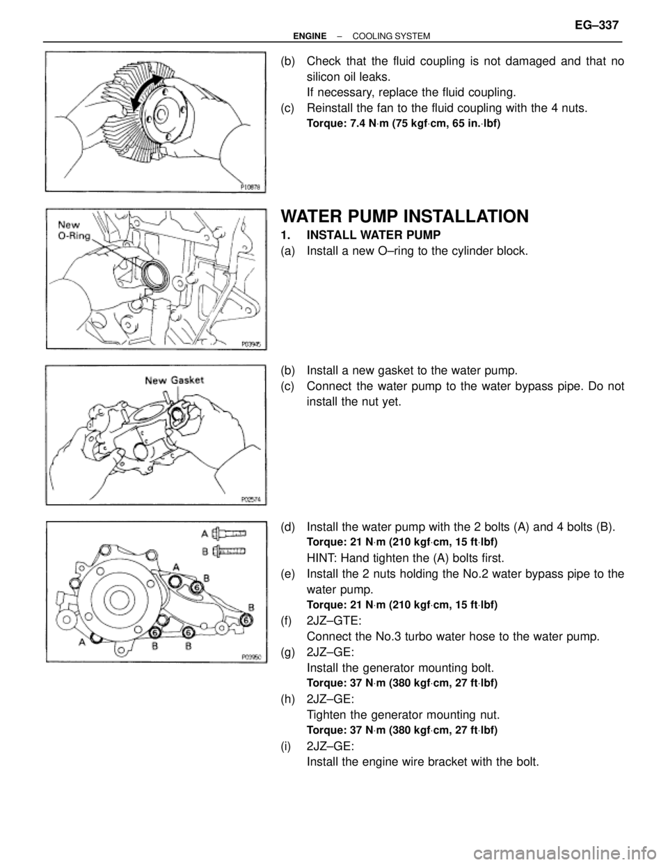
WATER PUMP INSTALLATION
1. INSTALL WATER PUMP
(a) Install a new O±ring to the cylinder block.
(b) Install a new gasket to the water pump.
(c) Connect the water pump to the water bypass pipe. Do not
install the nut yet.
(d) Install the water pump with the 2 bolts (A) and 4 bolts (B).
Torque: 21 NVm (210 kgfVcm, 15 ftVlbf)
HINT: Hand tighten the (A) bolts first.
(e) Install the 2 nuts holding the No.2 water bypass pipe to the
water pump.
Torque: 21 NVm (210 kgfVcm, 15 ftVlbf)
(f) 2JZ±GTE:
Connect the No.3 turbo water hose to the water pump.
(g) 2JZ±GE:
Install the generator mounting bolt.
Torque: 37 NVm (380 kgfVcm, 27 ftVlbf)
(h) 2JZ±GE:
Tighten the generator mounting nut.
Torque: 37 NVm (380 kgfVcm, 27 ftVlbf)
(i) 2JZ±GE:
Install the engine wire bracket with the bolt.
± ENGINECOOLING SYSTEMEG±337
Page 589 of 878
RADIATOR REMOVAL
Installation is in the reverse order of removal.
1. REMOVE ENGINE UNDER COVER
INSTALLATION HINT: Start the engine, and check for cool-
ant and A/T fluid leaks.
2. REMOVE BATTERY AND BATTERY TRAY
3. DRAIN ENGINE COOLANT
4. 2JZ±GTE:
REMOVE NO.2 AIR TUBE
5. REMOVE NO.2 FAN SHROUD
(a) Remove the 2 clips.
(b) Disconnect the claw of the No.2 fan shroud from the hook of
the No.1 fan shroud, and remove the No.2 fan shroud.
6. REMOVE AIR CLEANER DUCT
7. 2JZ±GTE:
REMOVE NO.5 AIR HOSE
8. REMOVE LH HEADLIGHT BEAM ANGLE GAUGE
Remove the screw and beam angle gauge.
9. DISCONNECT HOSES FROM RADIATOR
Disconnect these hoses from the radiator:
(1) Reservoir inlet hose
(2) Upper radiator hose
(3) Lower radiator hose
(4) A/T:
2 oil cooler hoses
Plug the hose ends.
INSTALLATION HINT: Check the A/T fluid level.
(See item 21 in Maintenance) EG±346
± ENGINECOOLING SYSTEM
Page 593 of 878

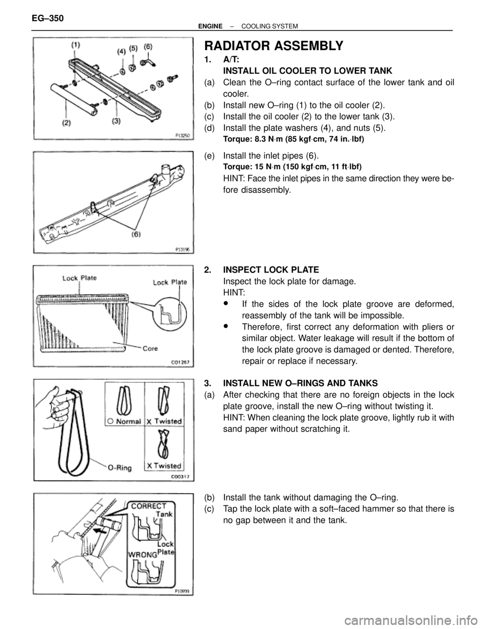
RADIATOR ASSEMBLY
1. A/T:
INSTALL OIL COOLER TO LOWER TANK
(a) Clean the O±ring contact surface of the lower tank and oil
cooler.
(b) Install new O±ring (1) to the oil cooler (2).
(c) Install the oil cooler (2) to the lower tank (3).
(d) Install the plate washers (4), and nuts (5).
Torque: 8.3 NVm (85 kgfVcm, 74 in.Vlbf)
(e) Install the inlet pipes (6).
Torque: 15 NVm (150 kgfVcm, 11 ftVlbf)
HINT: Face the inlet pipes in the same direction they were be-
fore disassembly.
2. INSPECT LOCK PLATE
Inspect the lock plate for damage.
HINT:
wIf the sides of the lock plate groove are deformed,
reassembly of the tank will be impossible.
wTherefore, first correct any deformation with pliers or
similar object. Water leakage will result if the bottom of
the lock plate groove is damaged or dented. Therefore,
repair or replace if necessary.
3. INSTALL NEW O±RINGS AND TANKS
(a) After checking that there are no foreign objects in the lock
plate groove, install the new O±ring without twisting it.
HINT: When cleaning the lock plate groove, lightly rub it with
sand paper without scratching it.
(b) Install the tank without damaging the O±ring.
(c) Tap the lock plate with a soft±faced hammer so that there is
no gap between it and the tank. EG±350
± ENGINECOOLING SYSTEM
Page 599 of 878

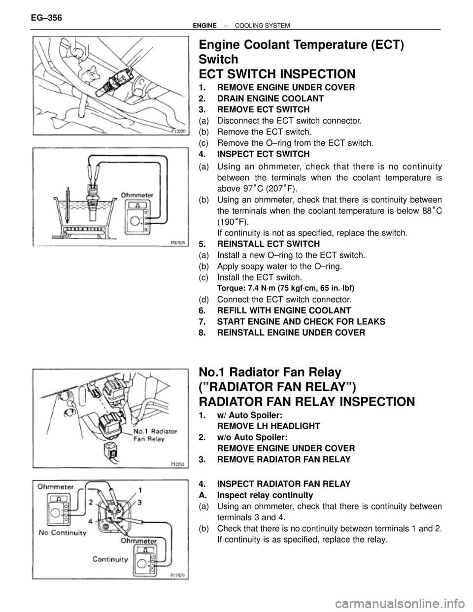
Engine Coolant Temperature (ECT)
Switch
ECT SWITCH INSPECTION
1. REMOVE ENGINE UNDER COVER
2. DRAIN ENGINE COOLANT
3. REMOVE ECT SWITCH
(a) Disconnect the ECT switch connector.
(b) Remove the ECT switch.
(c) Remove the O±ring from the ECT switch.
4. INSPECT ECT SWITCH
(a) Usin g an oh mme te r, ch e ck th a t th e re is no co n tin u ity
between the terminals when the coolant temperature is
above 97°C (207°F).
(b) Using an ohmmeter, check that there is continuity between
the terminals when the coolant temperature is below 88°C
(190°F).
If continuity is not as specified, replace the switch.
5. REINSTALL ECT SWITCH
(a) Install a new O±ring to the ECT switch.
(b) Apply soapy water to the O±ring.
(c) Install the ECT switch.
Torque: 7.4 NVm (75 kgfVcm, 65 in.Vlbf)
(d) Connect the ECT switch connector.
6. REFILL WITH ENGINE COOLANT
7. START ENGINE AND CHECK FOR LEAKS
8. REINSTALL ENGINE UNDER COVER
No.1 Radiator Fan Relay
(ºRADIATOR FAN RELAYº)
RADIATOR FAN RELAY INSPECTION
1. w/ Auto Spoiler:
REMOVE LH HEADLIGHT
2. w/o Auto Spoiler:
REMOVE ENGINE UNDER COVER
3. REMOVE RADIATOR FAN RELAY
4. INSPECT RADIATOR FAN RELAY
A. Inspect relay continuity
(a) Using an ohmmeter, check that there is continuity between
terminals 3 and 4.
(b) Check that there is no continuity between terminals 1 and 2.
If continuity is as specified, replace the relay. EG±356
± ENGINECOOLING SYSTEM