Page 505 of 878
8. INSTALL FUEL PIPE SUPPORT
Torque: 14 NVm (145 kgfVcm, 10 ftVlbf)
9. INSTALL LH ENGINE MOUNTING BRACKET AND
INSULATOR ASSEMBLY
HINT: LH mounting bracket is marked ºA u INº.
Torque: 58 NVm (590 kgfVcm, 43 ftVlbf)
10. INSTALL OIL FILTER BRACKET
(a) Check and clean the oil filter bracket installation.
(b) Place a new O±ring in position on the oil filter bracket.
(c) Apply clean engine oil to the O±ring.
(d) Install a new gasket to the union bolt.
(e) Install the oil filter braket with the union bolt.
Torque: 88 NVm (900 kgfVcm, 65 ftVlbf)
11. INSTALL NO.2 WATER BYPASS PIPE
(a) Install a new gasket to the water pump.
(b) 2JZ±GE:
Install the water bypass pipe with the bolt and 2 nuts.
Torque: 21 NVm (210 kgfVcm, 15 ftVlbf)
(c) 2JZ±GTE:
Install the water bypass pipe with the 2 bolts and 2 nuts.
Torque: 21 NVm (210 kgfVcm, 15 ftVlbf)
12. 2JZ±GTE:
INSTALL OIL COOLER
(See oil cooler installation in Lubrication System)
13. INSTALL OIL FILTER
(See oil and filter replacement in Lubrication System)
14. INSTALL CYLINDER HEAD
(See cylinder head installation)
15. INSTALL TIMING PULLEYS AND BELT
(See timing belt installation)
16. INSTALL GENERATOR
(See generator installation in Charging System)
17. REMOVE ENGINE STAND FROM ENGINE
18. M/T:
INSTALL FLYWHEEL
HINT: The flywheel bolts are tightened in 2 progressive step,
(b) and (d).
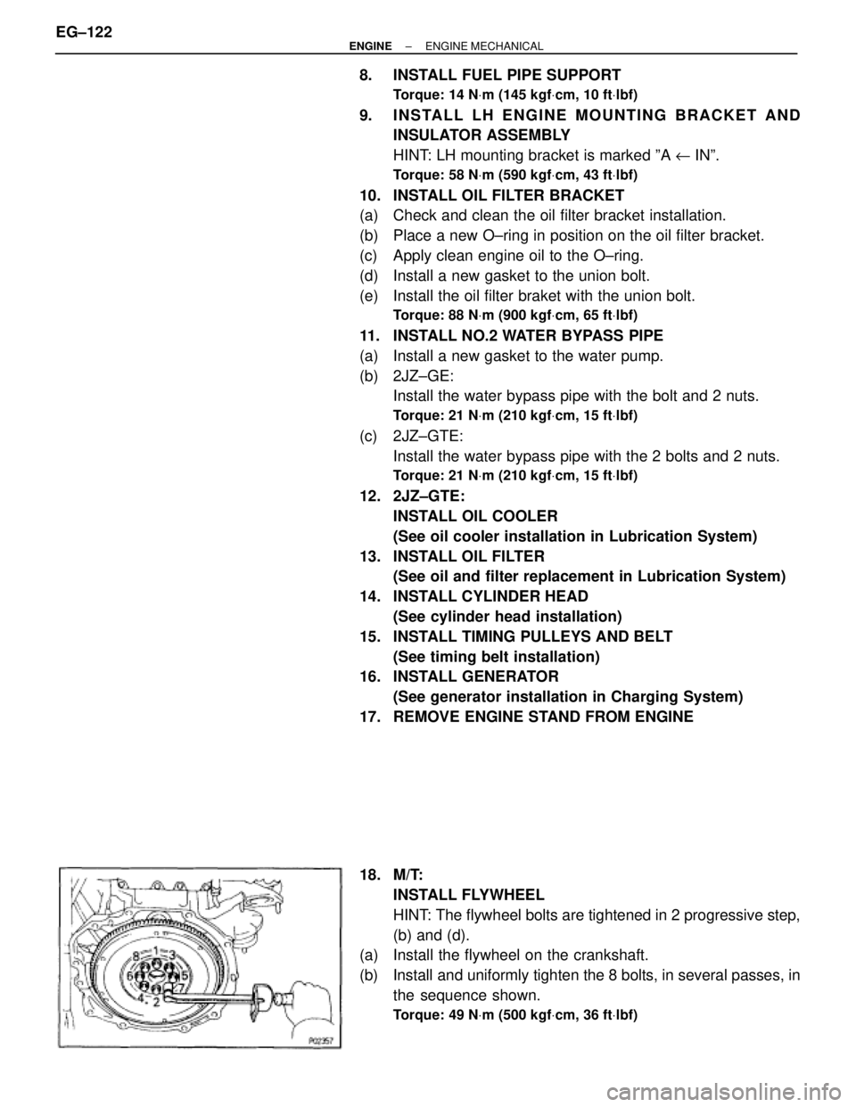
(a) Install the flywheel on the crankshaft.
(b) Install and uniformly tighten the 8 bolts, in several passes, in
the sequence shown.
Torque: 49 NVm (500 kgfVcm, 36 ftVlbf)
EG±122± ENGINEENGINE MECHANICAL
Page 511 of 878
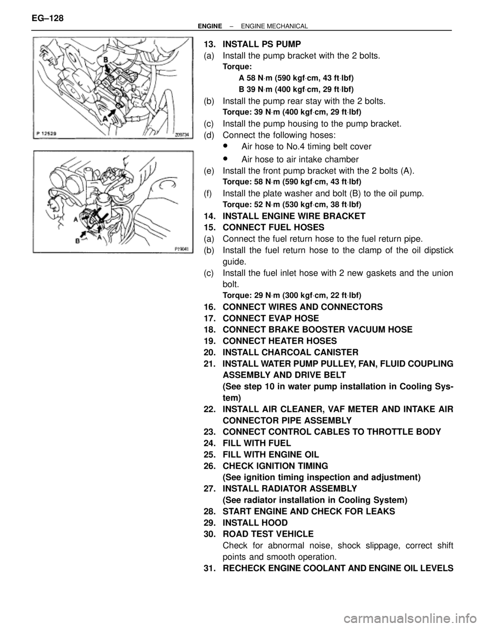
13. INSTALL PS PUMP
(a) Install the pump bracket with the 2 bolts.
Torque:
A 58 NVm (590 kgfVcm, 43 ftVlbf)
B 39 NVm (400 kgfVcm, 29 ftVlbf)
(b) Install the pump rear stay with the 2 bolts.
Torque: 39 NVm (400 kgfVcm, 29 ftVlbf)
(c) Install the pump housing to the pump bracket.
(d) Connect the following hoses:
wAir hose to No.4 timing belt cover
wAir hose to air intake chamber
(e) Install the front pump bracket with the 2 bolts (A).
Torque: 58 NVm (590 kgfVcm, 43 ftVlbf)
(f) Install the plate washer and bolt (B) to the oil pump.
Torque: 52 NVm (530 kgfVcm, 38 ftVlbf)
14. INSTALL ENGINE WIRE BRACKET
15. CONNECT FUEL HOSES
(a) Connect the fuel return hose to the fuel return pipe.
(b) Install the fuel return hose to the clamp of the oil dipstick
guide.
(c) Install the fuel inlet hose with 2 new gaskets and the union
bolt.
Torque: 29 NVm (300 kgfVcm, 22 ftVlbf)
16. CONNECT WIRES AND CONNECTORS
17. CONNECT EVAP HOSE
18. CONNECT BRAKE BOOSTER VACUUM HOSE
19. CONNECT HEATER HOSES
20. INSTALL CHARCOAL CANISTER
21. INSTALL WATER PUMP PULLEY, FAN, FLUID COUPLING
ASSEMBLY AND DRIVE BELT
(See step 10 in water pump installation in Cooling Sys-
tem)
22. INSTALL AIR CLEANER, VAF METER AND INTAKE AIR
CONNECTOR PIPE ASSEMBLY
23. CONNECT CONTROL CABLES TO THROTTLE BODY
24. FILL WITH FUEL
25. FILL WITH ENGINE OIL
26. CHECK IGNITION TIMING
(See ignition timing inspection and adjustment)
27. INSTALL RADIATOR ASSEMBLY
(See radiator installation in Cooling System)
28. START ENGINE AND CHECK FOR LEAKS
29. INSTALL HOOD
30. ROAD TEST VEHICLE
Check for abnormal noise, shock slippage, correct shift
points and smooth operation.
31. RECHECK ENGINE COOLANT AND ENGINE OIL LEVELS EG±128
± ENGINEENGINE MECHANICAL
Page 514 of 878
13. CONNECT ENGINE WIRE TO COWL PANEL
14. INSTALL A/C COMPRESSOR
(a) Using a torx socket (E10), install the stud bolt and and
compressor.
Torque: 26 NVm (265 kgfVcm, 19 ftVlbf)
(b) Connect the compressor connector.
(c) Temporarily install the compressor with nut and 3 bolts.
(d) Alternately tighten the bolt and nut.
Torque: 52 NVm (530 kgfVcm, 38 ftVlbf)
15. INSTALL PS PRESSURE TUBE
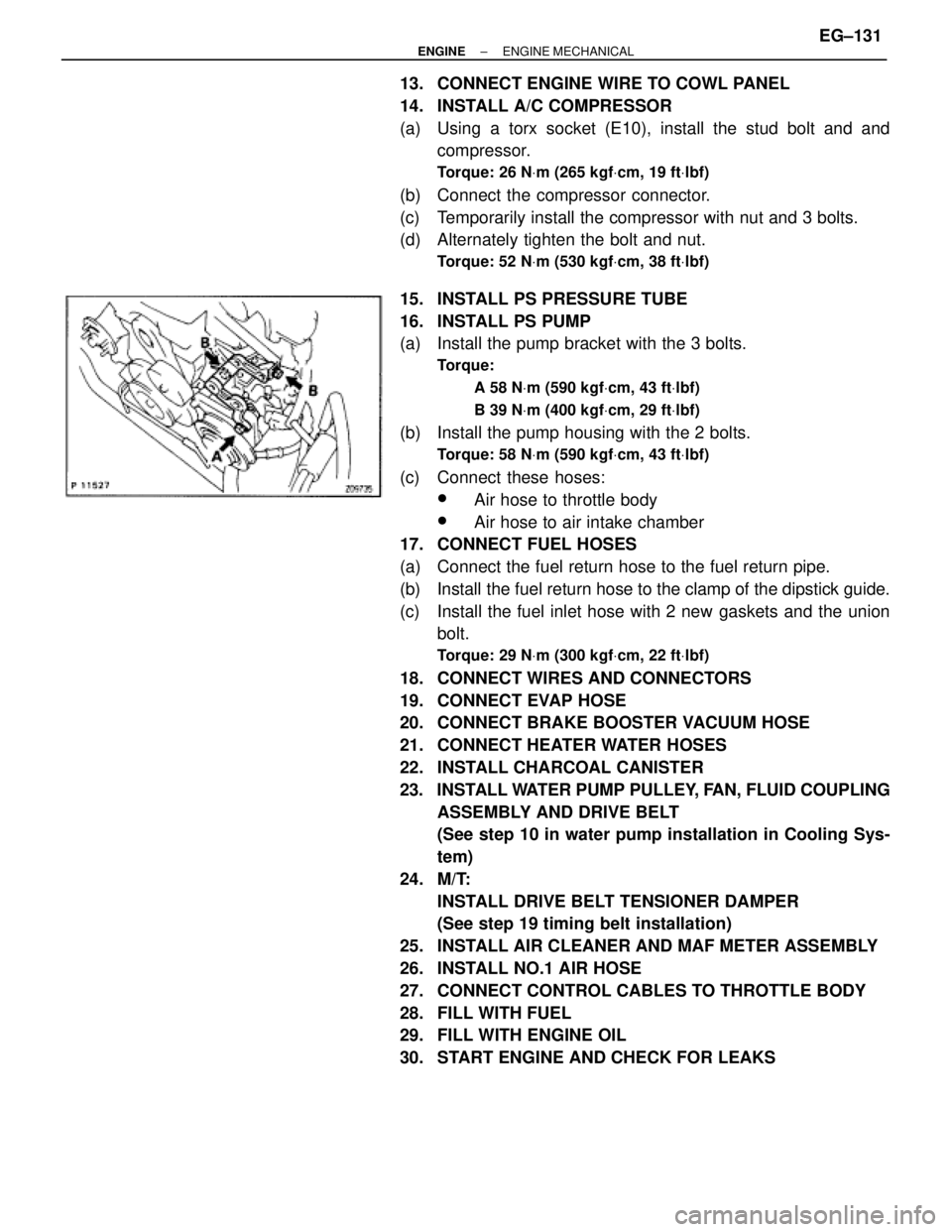
16. INSTALL PS PUMP
(a) Install the pump bracket with the 3 bolts.
Torque:
A 58 NVm (590 kgfVcm, 43 ftVlbf)
B 39 NVm (400 kgfVcm, 29 ftVlbf)
(b) Install the pump housing with the 2 bolts.
Torque: 58 NVm (590 kgfVcm, 43 ftVlbf)
(c) Connect these hoses:
wAir hose to throttle body
wAir hose to air intake chamber
17. CONNECT FUEL HOSES
(a) Connect the fuel return hose to the fuel return pipe.
(b) Install the fuel return hose to the clamp of the dipstick guide.
(c) Install the fuel inlet hose with 2 new gaskets and the union
bolt.
Torque: 29 NVm (300 kgfVcm, 22 ftVlbf)
18. CONNECT WIRES AND CONNECTORS
19. CONNECT EVAP HOSE
20. CONNECT BRAKE BOOSTER VACUUM HOSE
21. CONNECT HEATER WATER HOSES
22. INSTALL CHARCOAL CANISTER
23. INSTALL WATER PUMP PULLEY, FAN, FLUID COUPLING
ASSEMBLY AND DRIVE BELT
(See step 10 in water pump installation in Cooling Sys-
tem)
24. M/T:
INSTALL DRIVE BELT TENSIONER DAMPER
(See step 19 timing belt installation)
25. INSTALL AIR CLEANER AND MAF METER ASSEMBLY
26. INSTALL NO.1 AIR HOSE
27. CONNECT CONTROL CABLES TO THROTTLE BODY
28. FILL WITH FUEL
29. FILL WITH ENGINE OIL
30. START ENGINE AND CHECK FOR LEAKS
± ENGINEENGINE MECHANICALEG±131
Page 515 of 878
31. CHECK IGNITION TIMING
(See ignition timing inspection)
32. INSTALL RADIATOR ASSEMBLY
(See radiator installation in Cooling System)
33. INSTALL HOOD
34. ROAD TEST VEHICLE
Check for abnormal noise, shock slippage, correct shift
points and smooth operation.
35. RECHECK ENGINE COOLANT AND ENGINE OIL LEVELS EG±132
± ENGINEENGINE MECHANICAL
Page 525 of 878
OIL PRESSURE CHECK
1. CHECK OIL QUALITY
Check the oil for deterioration, entry of water, discoloring or
thinning.
If oil quality is visibly poor, replace the oil.
2. CHECK ENGINE OIL LEVEL
The oil level should be between the ºLº and ºFº marks on the
dipstick.
If low, check for the leakage and add oil up to ºFº mark.
3. REMOVE ENGINE UNDER COVER
4. 2JZ±GTE:
REMOVE NO.2 AIR TUBE
Loosen the 2 hose clamps, and remove 2 bolts and air tube.
5. 2JZ±GTE M/T:
REMOVE DRIVE BELT TENSIONER DAMPER
Remove the 2 nuts and tensioner damper.
6. DISCONNECT A/C COMPRESSOR FROM ENGINE
(a) Loosen the drive belt tension by turning the drive belt
tensioner clockwise, and remove the drive belt.
(b) Remove the 4 bolts and nut.
(c) Using a torx socket (E10), remove the stud bolt.
(d) Disconnect the compressor connector.
(e) Remove 4 bolts and pull the compressor downward.
± ENGINELUBRICATION SYSTEMEG±361
Page 526 of 878
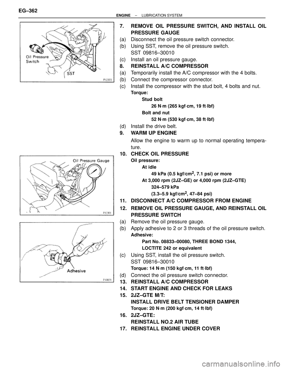
7. REMOVE OIL PRESSURE SWITCH, AND INSTALL OIL
PRESSURE GAUGE
(a) Disconnect the oil pressure switch connector.
(b) Using SST, remove the oil pressure switch.
SST 09816±30010
(c) Install an oil pressure gauge.
8. REINSTALL A/C COMPRESSOR
(a) Temporarily install the A/C compressor with the 4 bolts.
(b) Connect the compressor connector.
(c) Install the compressor with the stud bolt, 4 bolts and nut.
Torque:
Stud bolt
26 NVm (265 kgfVcm, 19 ftVlbf)
Bolt and nut
52 NVm (530 kgfVcm, 38 ftVlbf)
(d) Install the drive belt.
9. WARM UP ENGINE
Allow the engine to warm up to normal operating tempera-
ture.
10. CHECK OIL PRESSURE
Oil pressure:
At idle
49 kPa (0.5 kgf/cm
2, 7.1 psi) or more
At 3,000 rpm (2JZ±GE) or 4,000 rpm (2JZ±GTE)
324±579 kPa
(3.3±5.9 kgf/cm
2, 47±84 psi)
11. DISCONNECT A/C COMPRESSOR FROM ENGINE
12. REMOVE OIL PRESSURE GAUGE, AND REINSTALL OIL
PRESSURE SWITCH
(a) Remove the oil pressure gauge.
(b) Apply adhesive to 2 or 3 threads of the oil pressure switch.
Adhesive:
Part No. 08833±00080, THREE BOND 1344,
LOCTITE 242 or equivalent
(c) Using SST, install the oil pressure switch.
SST 09816±30010
Torque: 14 NVm (150 kgfVcm, 11 ftVlbf)
(d) Connect the oil pressure switch connector.
13. REINSTALL A/C COMPRESSOR
14. START ENGINE AND CHECK FOR LEAKS
15. 2JZ±GTE M/T:
INSTALL DRIVE BELT TENSIONER DAMPER
Torque: 20 NVm (200 kgfVcm, 14 ftVlbf)
16. 2JZ±GTE:
REINSTALL NO.2 AIR TUBE
17. REINSTALL ENGINE UNDER COVER EG±362
± ENGINELUBRICATION SYSTEM
Page 527 of 878
OIL AND FILTER REPLACEMENT
CAUTION:
wProlonged and repeated contact with mineral oil will re-
sult in the removal of natural fats from the skin, leading
to dryness, irritation and dermatitis. In addition, used en-
gine oil contains potentially harmful contaminants which
may cause skin cancer.
wExercise caution in order to minimize the length and fre-
quency of contact of your skin to used oil. Wear protec-
tive clothing and gloves. Wash your skin thoroughly with
soap and water, or use waterless hand cleaner, to remove
any used engine oil. Do not use gasoline, thinners, or sol-
vents.
wIn order to preserve the environment, used oil and used
oil filters must be disposed of only at designated dispos-
al sites.
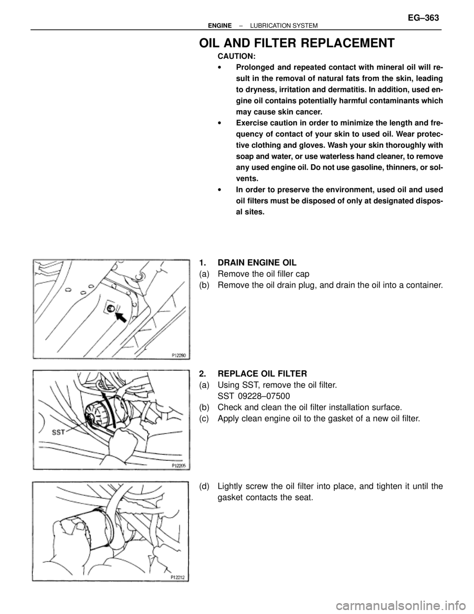
1. DRAIN ENGINE OIL
(a) Remove the oil filler cap
(b) Remove the oil drain plug, and drain the oil into a container.
2. REPLACE OIL FILTER
(a) Using SST, remove the oil filter.
SST 09228±07500
(b) Check and clean the oil filter installation surface.
(c) Apply clean engine oil to the gasket of a new oil filter.
(d) Lightly screw the oil filter into place, and tighten it until the
gasket contacts the seat.
± ENGINELUBRICATION SYSTEMEG±363
Page 528 of 878
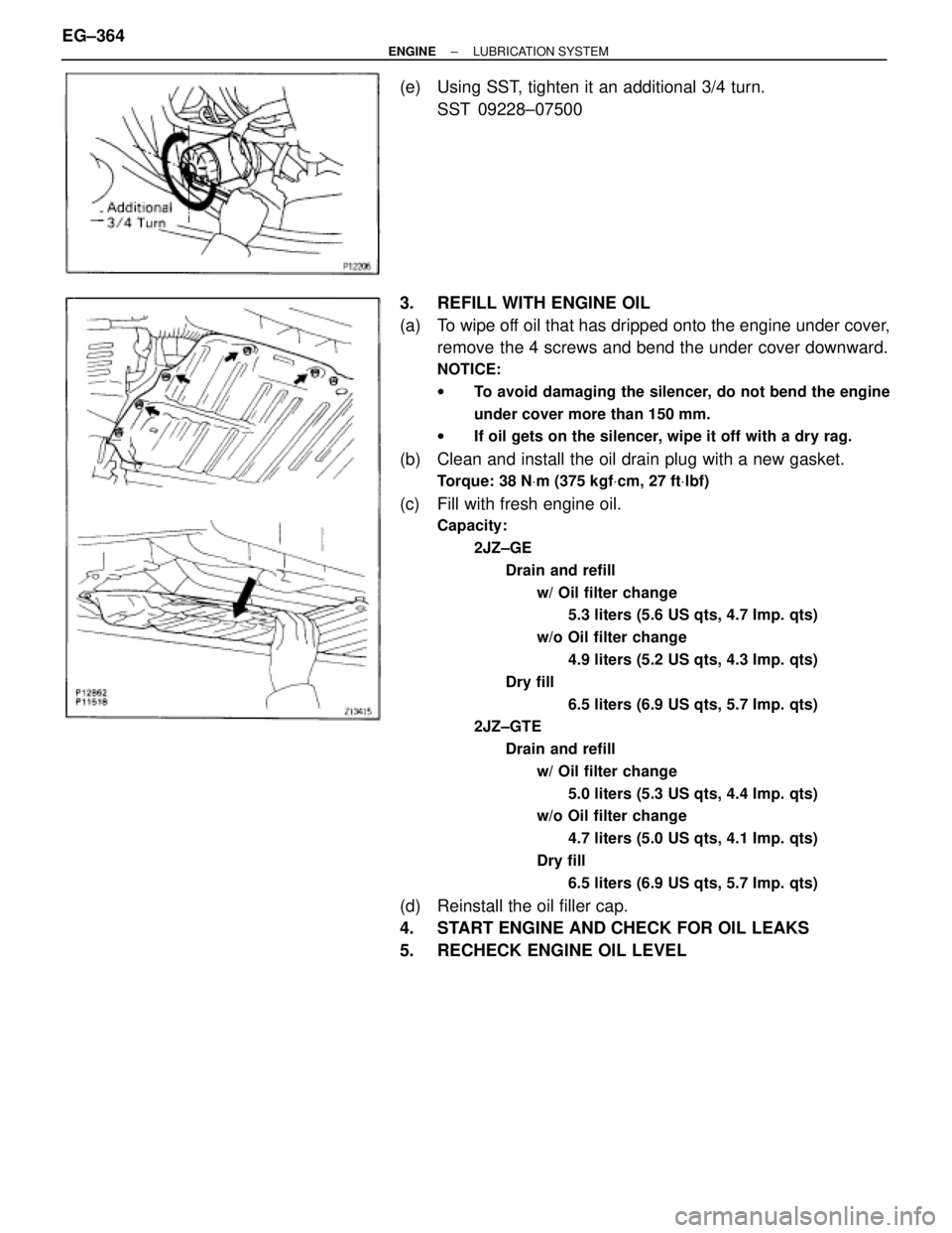
(e) Using SST, tighten it an additional 3/4 turn.
SST 09228±07500
3. REFILL WITH ENGINE OIL
(a) To wipe off oil that has dripped onto the engine under cover,
remove the 4 screws and bend the under cover downward.
NOTICE:
wTo avoid damaging the silencer, do not bend the engine
under cover more than 150 mm.
wIf oil gets on the silencer, wipe it off with a dry rag.
(b) Clean and install the oil drain plug with a new gasket.
Torque: 38 NVm (375 kgfVcm, 27 ftVlbf)
(c) Fill with fresh engine oil.
Capacity:
2JZ±GE
Drain and refill
w/ Oil filter change
5.3 liters (5.6 US qts, 4.7 Imp. qts)
w/o Oil filter change
4.9 liters (5.2 US qts, 4.3 Imp. qts)
Dry fill
6.5 liters (6.9 US qts, 5.7 Imp. qts)
2JZ±GTE
Drain and refill
w/ Oil filter change
5.0 liters (5.3 US qts, 4.4 Imp. qts)
w/o Oil filter change
4.7 liters (5.0 US qts, 4.1 Imp. qts)
Dry fill
6.5 liters (6.9 US qts, 5.7 Imp. qts)
(d) Reinstall the oil filler cap.
4. START ENGINE AND CHECK FOR OIL LEAKS
5. RECHECK ENGINE OIL LEVEL EG±364
± ENGINELUBRICATION SYSTEM