Page 387 of 878
(09316±00050) Replacer ªDº
09330±00021Companion Flange Holding Tool
09608±30022 Front Hub Bearing Replacer Set
(09608±05010) Handle
09816±30010 Oil Pressure Switch Socket
09843±18020 Diagnosis Check Wire
09950±50010 Puller C Set
(09951±05010)Hanger 150
(09952±05010) Slide Arm
(09953±05020) Center Bolt 150
(09954±05010)Claw No.1
(09954±05030)Claw No.3
09960±10010 Variable Pin Wrench Set
(09962±01000) Variable Pin Wrench Arm AssyCamshaft timing pulley
Camshaft pulley
Crankshaft timing pulley
Crankshaft pulley
Crankshaft timing pulley
Crankshaft pulley
Crankshaft timing pulley
Crankshaft pulley
Crankshaft timing pulley
Knock sensor
Oil pressure switch
Crankshaft rear oil seal
Valve guide bushing
Crankshaft pulley
Camshaft oil seal
EG±4± ENGINEENGINE MECHANICAL
Page 392 of 878
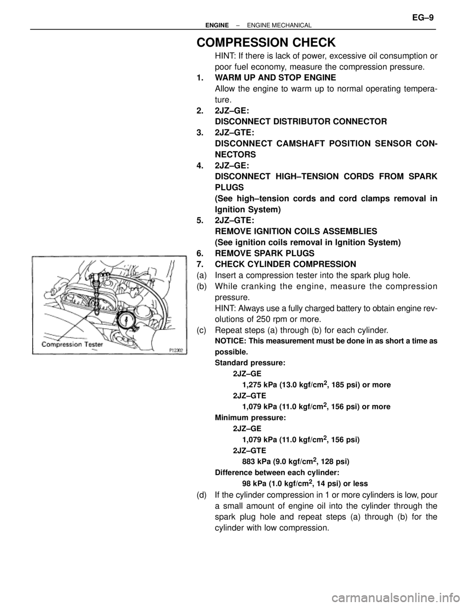
COMPRESSION CHECK
HINT: If there is lack of power, excessive oil consumption or
poor fuel economy, measure the compression pressure.
1. WARM UP AND STOP ENGINE
Allow the engine to warm up to normal operating tempera-
ture.
2. 2JZ±GE:
DISCONNECT DISTRIBUTOR CONNECTOR
3. 2JZ±GTE:
DISCONNECT CAMSHAFT POSITION SENSOR CON-
NECTORS
4. 2JZ±GE:
DISCONNECT HIGH±TENSION CORDS FROM SPARK
PLUGS
(See high±tension cords and cord clamps removal in
Ignition System)
5. 2JZ±GTE:
REMOVE IGNITION COILS ASSEMBLIES
(See ignition coils removal in Ignition System)
6. REMOVE SPARK PLUGS
7. CHECK CYLINDER COMPRESSION
(a) Insert a compression tester into the spark plug hole.
(b) Wh ile cra n kin g th e en g in e , me a su re th e co mp re ssio n
pressure.
HINT: Always use a fully charged battery to obtain engine rev-
olutions of 250 rpm or more.
(c) Repeat steps (a) through (b) for each cylinder.
NOTICE: This measurement must be done in as short a time as
possible.
Standard pressure:
2JZ±GE
1,275 kPa (13.0 kgf/cm
2, 185 psi) or more
2JZ±GTE
1,079 kPa (11.0 kgf/cm
2, 156 psi) or more
Minimum pressure:
2JZ±GE
1,079 kPa (11.0 kgf/cm
2, 156 psi)
2JZ±GTE
883 kPa (9.0 kgf/cm
2, 128 psi)
Difference between each cylinder:
98 kPa (1.0 kgf/cm
2, 14 psi) or less
(d) If the cylinder compression in 1 or more cylinders is low, pour
a small amount of engine oil into the cylinder through the
spark plug hole and repeat steps (a) through (b) for the
cylinder with low compression.
± ENGINEENGINE MECHANICALEG±9
Page 411 of 878
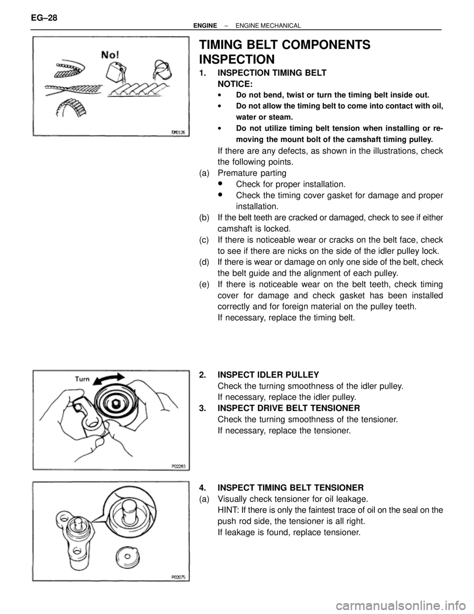
TIMING BELT COMPONENTS
INSPECTION
1. INSPECTION TIMING BELT
NOTICE:
wDo not bend, twist or turn the timing belt inside out.
wDo not allow the timing belt to come into contact with oil,
water or steam.
wDo not utilize timing belt tension when installing or re-
moving the mount bolt of the camshaft timing pulley.
If there are any defects, as shown in the illustrations, check
the following points.
(a) Premature parting
wCheck for proper installation.
wCheck the timing cover gasket for damage and proper
installation.
(b) If the belt teeth are cracked or damaged, check to see if either
camshaft is locked.
(c) If there is noticeable wear or cracks on the belt face, check
to see if there are nicks on the side of the idler pulley lock.
(d) If there is wear or damage on only one side of the belt, check
the belt guide and the alignment of each pulley.
(e) If there is noticeable wear on the belt teeth, check timing
cover for damage and check gasket has been installed
correctly and for foreign material on the pulley teeth.
If necessary, replace the timing belt.
2. INSPECT IDLER PULLEY
Check the turning smoothness of the idler pulley.
If necessary, replace the idler pulley.
3. INSPECT DRIVE BELT TENSIONER
Check the turning smoothness of the tensioner.
If necessary, replace the tensioner.
4. INSPECT TIMING BELT TENSIONER
(a) Visually check tensioner for oil leakage.
HINT: If there is only the faintest trace of oil on the seal on the
push rod side, the tensioner is all right.
If leakage is found, replace tensioner. EG±28
± ENGINEENGINE MECHANICAL
Page 413 of 878
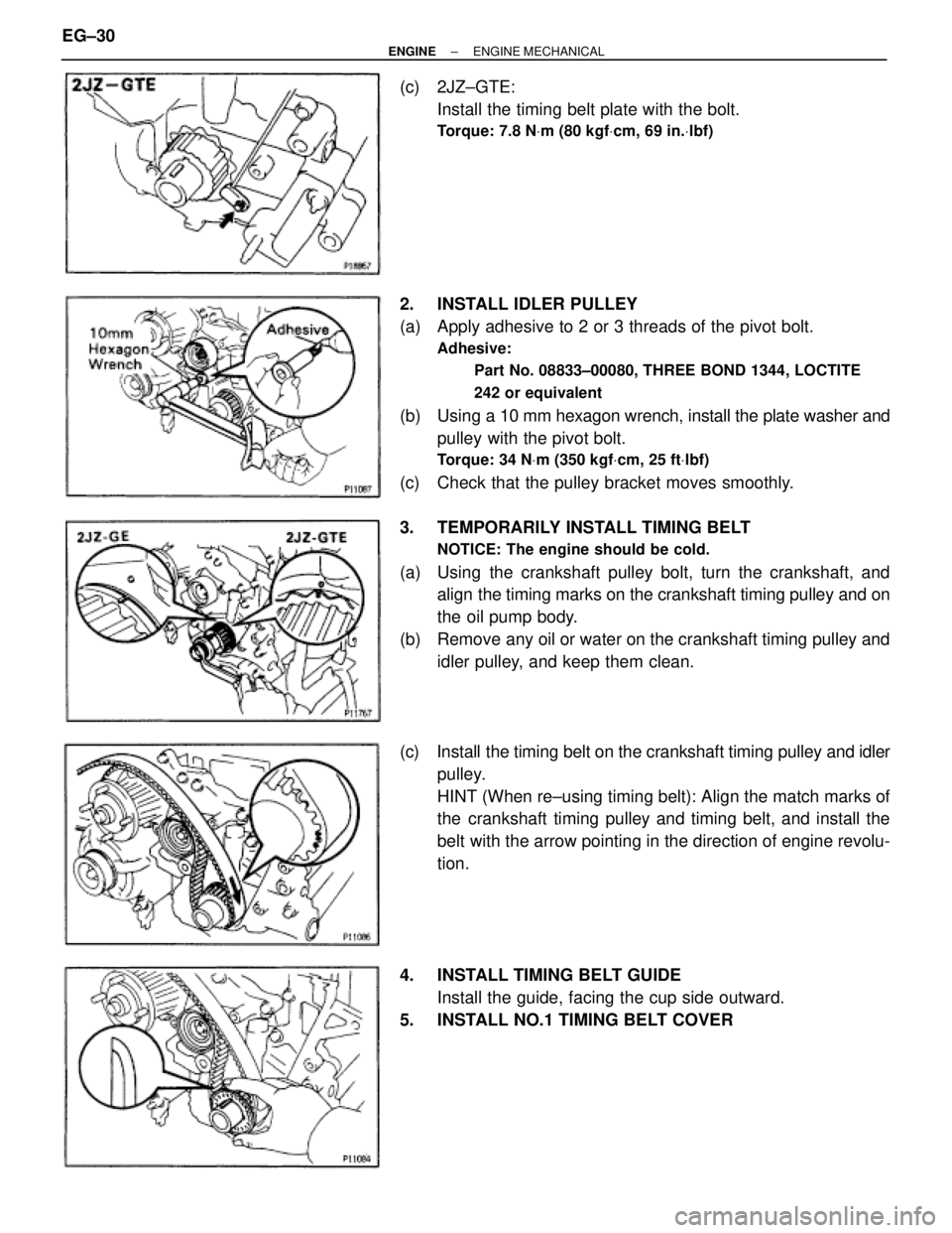
(c) 2JZ±GTE:
Install the timing belt plate with the bolt.
Torque: 7.8 NVm (80 kgfVcm, 69 in.Vlbf)
2. INSTALL IDLER PULLEY
(a) Apply adhesive to 2 or 3 threads of the pivot bolt.
Adhesive:
Part No. 08833±00080, THREE BOND 1344, LOCTITE
242 or equivalent
(b) Using a 10 mm hexagon wrench, install the plate washer and
pulley with the pivot bolt.
Torque: 34 NVm (350 kgfVcm, 25 ftVlbf)
(c) Check that the pulley bracket moves smoothly.
3. TEMPORARILY INSTALL TIMING BELT
NOTICE: The engine should be cold.
(a) Using the crankshaft pulley bolt, turn the crankshaft, and
align the timing marks on the crankshaft timing pulley and on
the oil pump body.
(b) Remove any oil or water on the crankshaft timing pulley and
idler pulley, and keep them clean.
(c) Install the timing belt on the crankshaft timing pulley and idler
pulley.
HINT (When re±using timing belt): Align the match marks of
the crankshaft timing pulley and timing belt, and install the
belt with the arrow pointing in the direction of engine revolu-
tion.
4. INSTALL TIMING BELT GUIDE
Install the guide, facing the cup side outward.
5. INSTALL NO.1 TIMING BELT COVER EG±30
± ENGINEENGINE MECHANICAL
Page 415 of 878
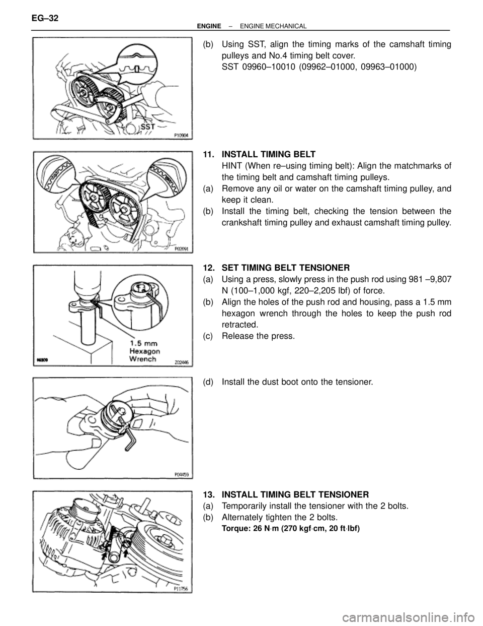
(b) Using SST, align the timing marks of the camshaft timing
pulleys and No.4 timing belt cover.
SST 09960±10010 (09962±01000, 09963±01000)
11. INSTALL TIMING BELT
HINT (When re±using timing belt): Align the matchmarks of
the timing belt and camshaft timing pulleys.
(a) Remove any oil or water on the camshaft timing pulley, and
keep it clean.
(b) Install the timing belt, checking the tension between the
crankshaft timing pulley and exhaust camshaft timing pulley.
12. SET TIMING BELT TENSIONER
(a) Using a press, slowly press in the push rod using 981 ±9,807
N (100±1,000 kgf, 220±2,205 lbf) of force.
(b) Align the holes of the push rod and housing, pass a 1.5 mm
hexagon wrench through the holes to keep the push rod
retracted.
(c) Release the press.
(d) Install the dust boot onto the tensioner.
13. INSTALL TIMING BELT TENSIONER
(a) Temporarily install the tensioner with the 2 bolts.
(b) Alternately tighten the 2 bolts.
Torque: 26 NVm (270 kgfVcm, 20 ftVlbf)
EG±32± ENGINEENGINE MECHANICAL
Page 440 of 878
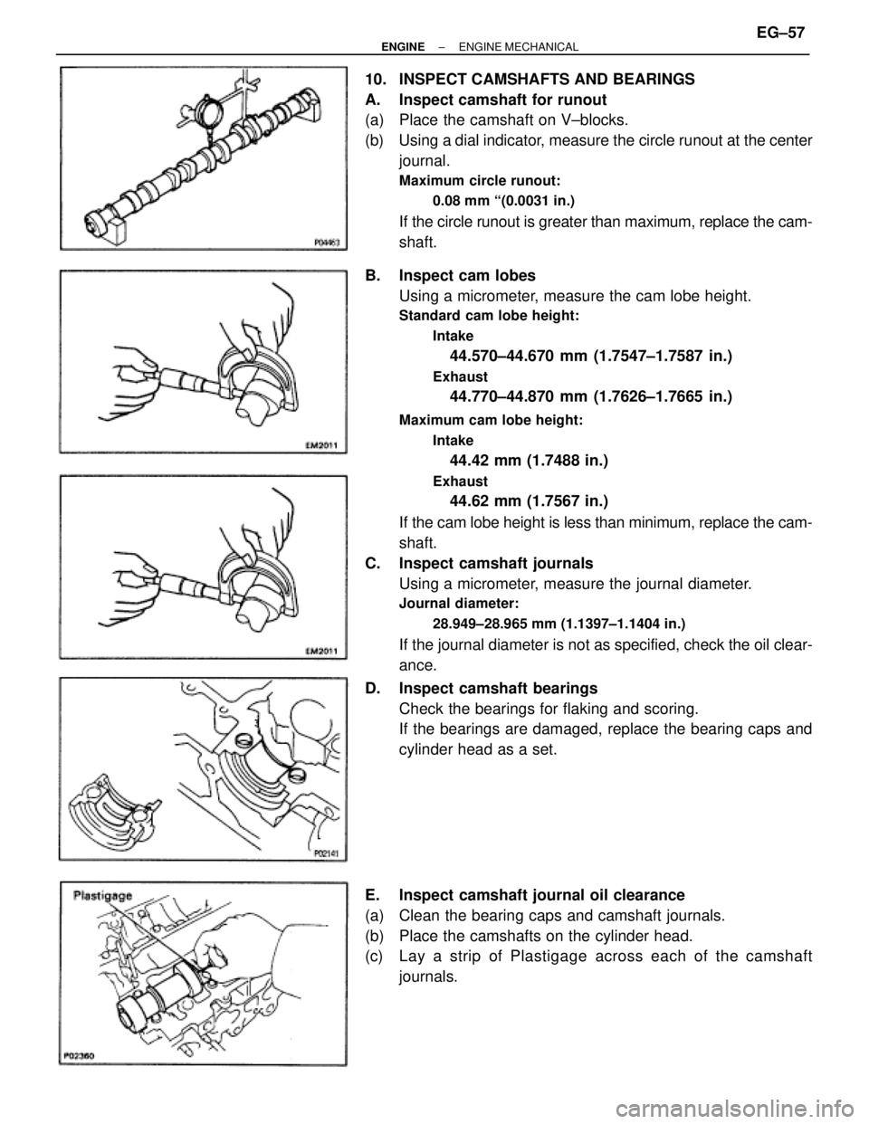
10. INSPECT CAMSHAFTS AND BEARINGS
A. Inspect camshaft for runout
(a) Place the camshaft on V±blocks.
(b) Using a dial indicator, measure the circle runout at the center
journal.
Maximum circle runout:
0.08 mm ª(0.0031 in.)
If the circle runout is greater than maximum, replace the cam-
shaft.
B. Inspect cam lobes
Using a micrometer, measure the cam lobe height.
Standard cam lobe height:
Intake
44.570±44.670 mm (1.7547±1.7587 in.)
Exhaust
44.770±44.870 mm (1.7626±1.7665 in.)
Maximum cam lobe height:
Intake
44.42 mm (1.7488 in.)
Exhaust
44.62 mm (1.7567 in.)
If the cam lobe height is less than minimum, replace the cam-
shaft.
C. Inspect camshaft journals
Using a micrometer, measure the journal diameter.
Journal diameter:
28.949±28.965 mm (1.1397±1.1404 in.)
If the journal diameter is not as specified, check the oil clear-
ance.
D. Inspect camshaft bearings
Check the bearings for flaking and scoring.
If the bearings are damaged, replace the bearing caps and
cylinder head as a set.
E. Inspect camshaft journal oil clearance
(a) Clean the bearing caps and camshaft journals.
(b) Place the camshafts on the cylinder head.
(c) Lay a strip of Plastigage across each of the camshaft
journals.
± ENGINEENGINE MECHANICALEG±57
Page 446 of 878
(e) Retighten the cylinder head bolts by 90° in the numerical
order shown in the illustration on previous page.
(f) Retighten cylinder head bolts by an additional 90° shown in
the illustration on previous page.
(g) Check that the painted mark is now turned to the rear.
2. INSTALL CAMSHAFTS
(a) Apply engine oil to the thrust portion of the camshaft.
(b) Place the camshaft on the cylinder head with the cam lobe
facing up as shown.
(c) Place the No.3 and No.7 bearing caps in their proper
location.
(d) Apply a light coat of engine oil on the threads and under the
heads of the bearing cap bolts.
(e) Temporarily tighten these bearing cap bolts uniformly and
alternately, in several passes, until the bearing caps are snug
with the cylinder head.
(f) Apply MP grease to a new camshaft oil seal lip.
± ENGINEENGINE MECHANICALEG±63
Page 448 of 878
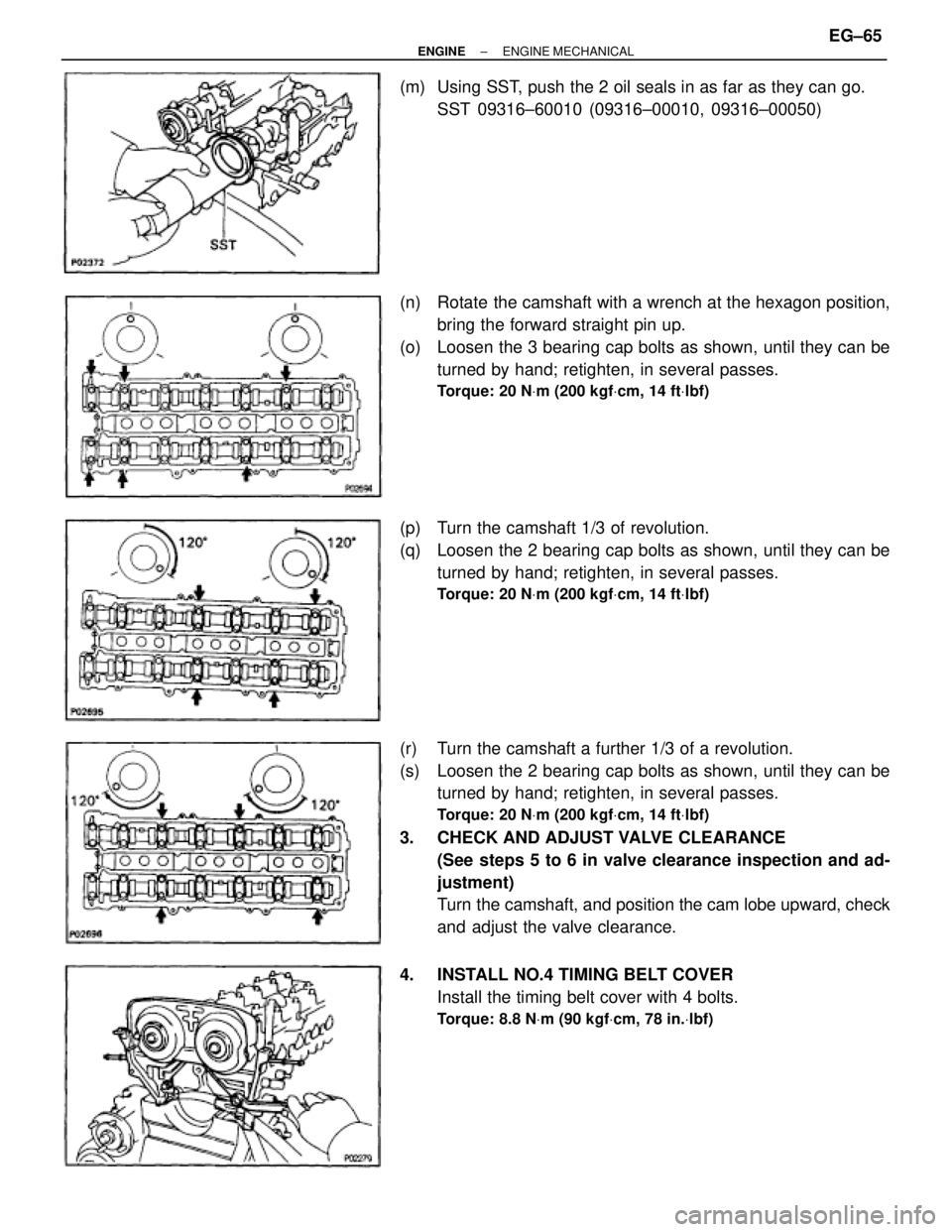
(m) Using SST, push the 2 oil seals in as far as they can go.
SST 09316±60010 (09316±00010, 09316±00050)
(n) Rotate the camshaft with a wrench at the hexagon position,
bring the forward straight pin up.
(o) Loosen the 3 bearing cap bolts as shown, until they can be
turned by hand; retighten, in several passes.
Torque: 20 NVm (200 kgfVcm, 14 ftVlbf)
(p) Turn the camshaft 1/3 of revolution.
(q) Loosen the 2 bearing cap bolts as shown, until they can be
turned by hand; retighten, in several passes.
Torque: 20 NVm (200 kgfVcm, 14 ftVlbf)
(r) Turn the camshaft a further 1/3 of a revolution.
(s) Loosen the 2 bearing cap bolts as shown, until they can be
turned by hand; retighten, in several passes.
Torque: 20 NVm (200 kgfVcm, 14 ftVlbf)
3. CHECK AND ADJUST VALVE CLEARANCE
(See steps 5 to 6 in valve clearance inspection and ad-
justment)
Turn the camshaft, and position the cam lobe upward, check
and adjust the valve clearance.
4. INSTALL NO.4 TIMING BELT COVER
Install the timing belt cover with 4 bolts.
Torque: 8.8 NVm (90 kgfVcm, 78 in.Vlbf)
± ENGINEENGINE MECHANICALEG±65