Page 403 of 878
IGNITION TIMING INSPECTION
(2JZ±GTE)
1. WARM UP ENGINE
Allow the engine to warm up to normal operating tempera-
ture.
2. CONNECT TACHOMETER AND TIMING LIGHT
(See step 2 in ignition timing inspection and adjustment
(2JZ±GE))
3. CHECK IDLE SPEED
(a) Race the engine speed at 2,500 rpm for approx. 90 seconds.
(b) Check the idle speed.
Idle speed:
650 + 50 rpm
4. CHECK IGNITION TIMING
(a) Using SST, connect terminals TE1 and E1 of the DLC 1.
SST 09843±18020
(b) Open the igniter connector cover and remove the green lead
wire.
(c) Connect the timing light clip to the green lead wire.
NOTICE:
wUse a timing light that can detect the primary signal.
wAfter finishing the inspection, make sure the lead wire is
stored inside the connector cover.
EG±20± ENGINEENGINE MECHANICAL
Page 404 of 878
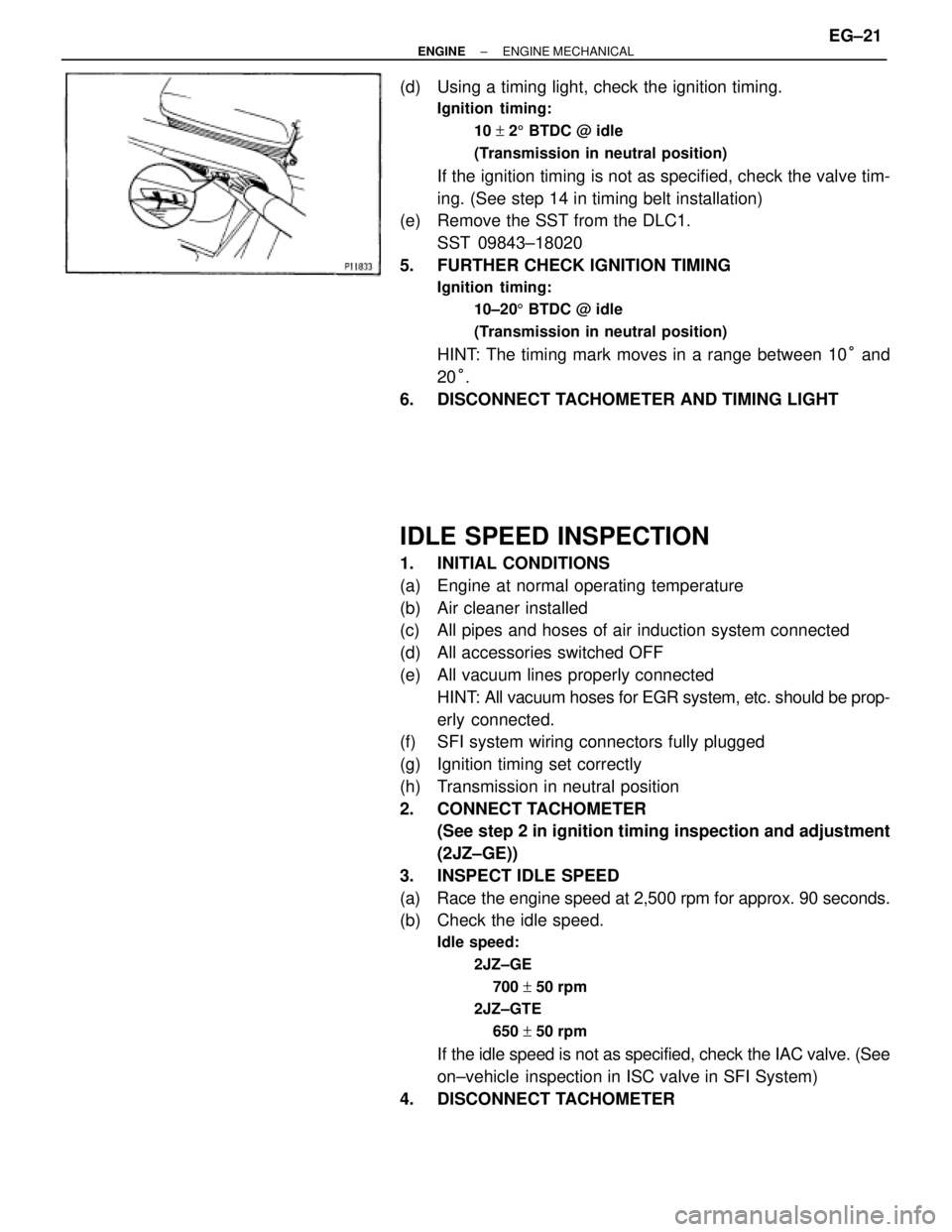
(d) Using a timing light, check the ignition timing.
Ignition timing:
10 + 25 BTDC @ idle
(Transmission in neutral position)
If the ignition timing is not as specified, check the valve tim-
ing. (See step 14 in timing belt installation)
(e) Remove the SST from the DLC1.
SST 09843±18020
5. FURTHER CHECK IGNITION TIMING
Ignition timing:
10±205 BTDC @ idle
(Transmission in neutral position)
HINT: The timing mark moves in a range between 10° and
20°.
6. DISCONNECT TACHOMETER AND TIMING LIGHT
IDLE SPEED INSPECTION
1. INITIAL CONDITIONS
(a) Engine at normal operating temperature
(b) Air cleaner installed
(c) All pipes and hoses of air induction system connected
(d) All accessories switched OFF
(e) All vacuum lines properly connected
HINT: All vacuum hoses for EGR system, etc. should be prop-
erly connected.
(f) SFI system wiring connectors fully plugged
(g) Ignition timing set correctly
(h) Transmission in neutral position
2. CONNECT TACHOMETER
(See step 2 in ignition timing inspection and adjustment
(2JZ±GE))
3. INSPECT IDLE SPEED
(a) Race the engine speed at 2,500 rpm for approx. 90 seconds.
(b) Check the idle speed.
Idle speed:
2JZ±GE
700 + 50 rpm
2JZ±GTE
650 + 50 rpm
If the idle speed is not as specified, check the IAC valve. (See
on±vehicle inspection in ISC valve in SFI System)
4. DISCONNECT TACHOMETER
± ENGINEENGINE MECHANICALEG±21
Page 438 of 878
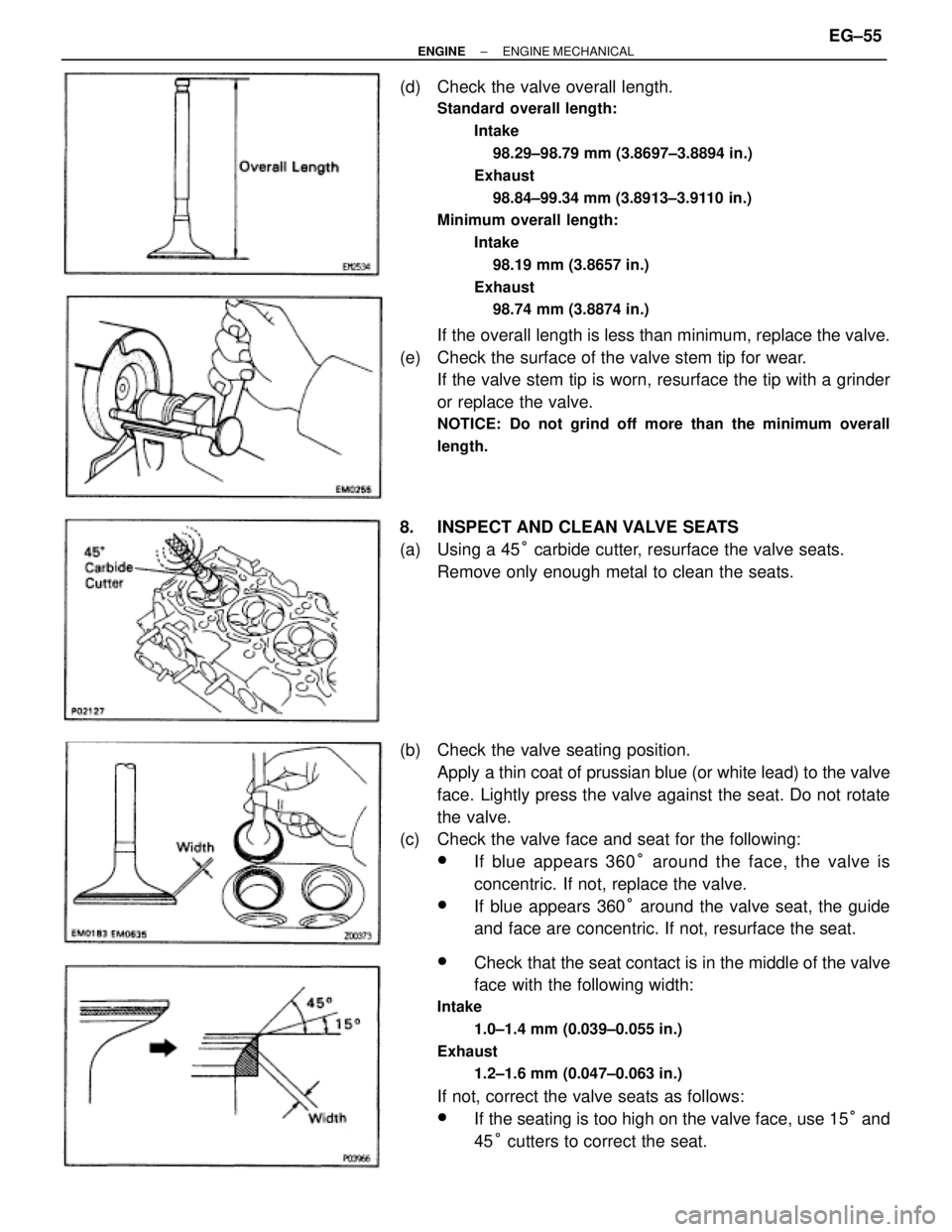
(d) Check the valve overall length.
Standard overall length:
Intake
98.29±98.79 mm (3.8697±3.8894 in.)
Exhaust
98.84±99.34 mm (3.8913±3.9110 in.)
Minimum overall length:
Intake
98.19 mm (3.8657 in.)
Exhaust
98.74 mm (3.8874 in.)
If the overall length is less than minimum, replace the valve.
(e) Check the surface of the valve stem tip for wear.
If the valve stem tip is worn, resurface the tip with a grinder
or replace the valve.
NOTICE: Do not grind off more than the minimum overall
length.
8. INSPECT AND CLEAN VALVE SEATS
(a) Using a 45° carbide cutter, resurface the valve seats.
Remove only enough metal to clean the seats.
(b) Check the valve seating position.
Apply a thin coat of prussian blue (or white lead) to the valve
face. Lightly press the valve against the seat. Do not rotate
the valve.
(c) Check the valve face and seat for the following:
wIf blue appears 360° around the face, the valve is
concentric. If not, replace the valve.
wIf blue appears 360° around the valve seat, the guide
and face are concentric. If not, resurface the seat.
wCheck that the seat contact is in the middle of the valve
face with the following width:
Intake
1.0±1.4 mm (0.039±0.055 in.)
Exhaust
1.2±1.6 mm (0.047±0.063 in.)
If not, correct the valve seats as follows:
wIf the seating is too high on the valve face, use 15° and
45° cutters to correct the seat.
± ENGINEENGINE MECHANICALEG±55
Page 444 of 878
(b) Install these parts:
(1) Valve
(2) Spring seat
(3) Valve spring
(4) Spring retainer
HINT: Install the valve spring, facing the painted mark up-
ward.
(c) Using SST, compress the valve spring and place the 2
keepers around the valve stem.
SST 09202±70010
(d) Using a plastic±faced hammer, lightly tap the valve stem tip
to ensure a proper fit.
3. INSTALL VALVE LIFTERS AND SHIMS
(a) Install the valve lifter and shim.
(b) Check that the valve lifter rotates smoothly by hand.
4. INSTALL EGR COOLER
Install a new gasket and the EGR cooler with the 8 bolts.
Torque: 8.8 NVm (90 kgfVcm, 78 in.Vlbf)
5. 2JZ±GE:
INSTALL ECT SENSOR AND SENDER GAUGE
Torque: 20 NVm (200 kgfVcm, 14 ftVlbf)
6. 2JZ±GE:
INSTALL GROUND STRAP AND THROTTLE CABLE
BRACKET
7. 2JZ±GE:
INSTALL ENGINE HANGERS
Torque: 39 NVm (400 kgfVcm, 29 ftVlbf)
± ENGINEENGINE MECHANICALEG±61
Page 446 of 878
(e) Retighten the cylinder head bolts by 90° in the numerical
order shown in the illustration on previous page.
(f) Retighten cylinder head bolts by an additional 90° shown in
the illustration on previous page.
(g) Check that the painted mark is now turned to the rear.
2. INSTALL CAMSHAFTS
(a) Apply engine oil to the thrust portion of the camshaft.
(b) Place the camshaft on the cylinder head with the cam lobe
facing up as shown.
(c) Place the No.3 and No.7 bearing caps in their proper
location.
(d) Apply a light coat of engine oil on the threads and under the
heads of the bearing cap bolts.
(e) Temporarily tighten these bearing cap bolts uniformly and
alternately, in several passes, until the bearing caps are snug
with the cylinder head.
(f) Apply MP grease to a new camshaft oil seal lip.
± ENGINEENGINE MECHANICALEG±63
Page 502 of 878
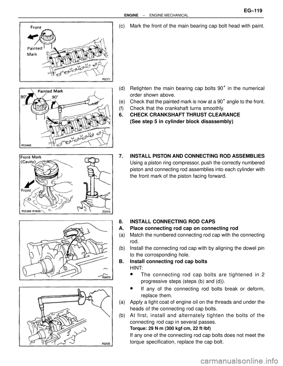
(c) Mark the front of the main bearing cap bolt head with paint.
(d) Retighten the main bearing cap bolts 90° in the numerical
order shown above.
(e) Check that the painted mark is now at a 90° angle to the front.
(f) Check that the crankshaft turns smoothly.
6. CHECK CRANKSHAFT THRUST CLEARANCE
(See step 5 in cylinder block disassembly)
7. INSTALL PISTON AND CONNECTING ROD ASSEMBLIES
Using a piston ring compressor, push the correctly numbered
piston and connecting rod assemblies into each cylinder with
the front mark of the piston facing forward.
8. INSTALL CONNECTING ROD CAPS
A. Place connecting rod cap on connecting rod
(a) Match the numbered connecting rod cap with the connecting
rod.
(b) Install the connecting rod cap with by aligning the dowel pin
to the corrosponding hole.
B. Install connecting rod cap bolts
HINT:
wThe connecting rod cap bolts are tightened in 2
progressive steps (steps (b) and (d)).
wIf any of the connecting rod bolts break or deform,
replace them.
(a) Apply a light coat of engine oil on the threads and under the
heads of the connecting rod cap bolts.
(b) A t first, in sta ll an d alte rn a te ly tig h te n th e bo lts of th e
connecting rod cap in several passes.
Torque: 29 NVm (300 kgfVcm, 22 ftVlbf)
If any one of the connecting rod cap bolts does not meet the
torque specification, replace the cap bolt.
± ENGINEENGINE MECHANICALEG±119
Page 527 of 878
OIL AND FILTER REPLACEMENT
CAUTION:
wProlonged and repeated contact with mineral oil will re-
sult in the removal of natural fats from the skin, leading
to dryness, irritation and dermatitis. In addition, used en-
gine oil contains potentially harmful contaminants which
may cause skin cancer.
wExercise caution in order to minimize the length and fre-
quency of contact of your skin to used oil. Wear protec-
tive clothing and gloves. Wash your skin thoroughly with
soap and water, or use waterless hand cleaner, to remove
any used engine oil. Do not use gasoline, thinners, or sol-
vents.
wIn order to preserve the environment, used oil and used
oil filters must be disposed of only at designated dispos-
al sites.
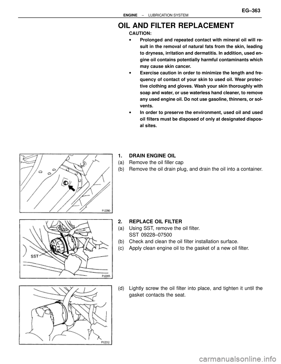
1. DRAIN ENGINE OIL
(a) Remove the oil filler cap
(b) Remove the oil drain plug, and drain the oil into a container.
2. REPLACE OIL FILTER
(a) Using SST, remove the oil filter.
SST 09228±07500
(b) Check and clean the oil filter installation surface.
(c) Apply clean engine oil to the gasket of a new oil filter.
(d) Lightly screw the oil filter into place, and tighten it until the
gasket contacts the seat.
± ENGINELUBRICATION SYSTEMEG±363
Page 542 of 878
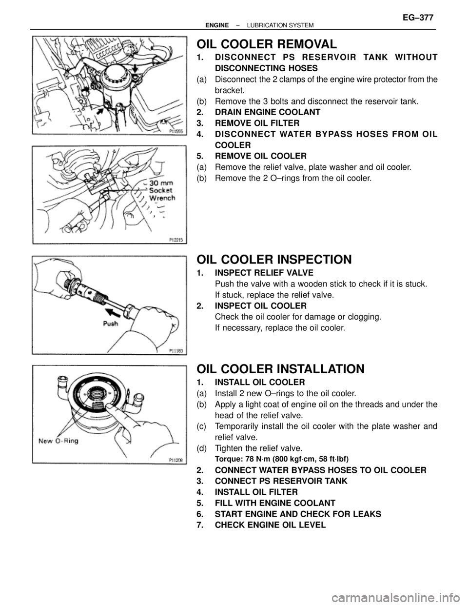
OIL COOLER REMOVAL
1. DISCONNECT PS RESERVOIR TANK WITHOUT
DISCONNECTING HOSES
(a) Disconnect the 2 clamps of the engine wire protector from the
bracket.
(b) Remove the 3 bolts and disconnect the reservoir tank.
2. DRAIN ENGINE COOLANT
3. REMOVE OIL FILTER
4. DISCONNECT WATER BYPASS HOSES FROM OIL
COOLER
5. REMOVE OIL COOLER
(a) Remove the relief valve, plate washer and oil cooler.
(b) Remove the 2 O±rings from the oil cooler.
OIL COOLER INSPECTION
1. INSPECT RELIEF VALVE
Push the valve with a wooden stick to check if it is stuck.
If stuck, replace the relief valve.
2. INSPECT OIL COOLER
Check the oil cooler for damage or clogging.
If necessary, replace the oil cooler.
OIL COOLER INSTALLATION
1. INSTALL OIL COOLER
(a) Install 2 new O±rings to the oil cooler.
(b) Apply a light coat of engine oil on the threads and under the
head of the relief valve.
(c) Temporarily install the oil cooler with the plate washer and
relief valve.
(d) Tighten the relief valve.
Torque: 78 NVm (800 kgfVcm, 58 ftVlbf)
2. CONNECT WATER BYPASS HOSES TO OIL COOLER
3. CONNECT PS RESERVOIR TANK
4. INSTALL OIL FILTER
5. FILL WITH ENGINE COOLANT
6. START ENGINE AND CHECK FOR LEAKS
7. CHECK ENGINE OIL LEVEL
± ENGINELUBRICATION SYSTEMEG±377