Page 206 of 878

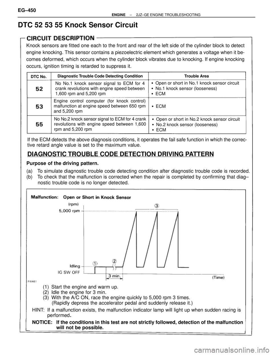
DTC 52 53 55 Knock Sensor Circuit
Knock sensors are fitted one each to the front and rear of the left side of the cylinder block to detect
engine knocking. This sensor contains a piezoelectric element which generates a voltage when it be-
comes deformed, which occurs when the cylinder block vibrates due to knocking. If engine knocking
occurs, ignition timing is retarded to suppress it.
DTC No.Diagnostic Trouble Code Detecting ConditionTrouble Area
No No.1 knock sensor signal to ECM for 4
crank revolutions with engine speed between
1,600 rpm and 5,200 rpm
Engine control computer (for knock control)
malfunction at engine speed between 650 rpm
and 5,200 rpm
No No.2 knock sensor signal to ECM for 4 crank
revolutions with engine speed between 1,600
rpm and 5,200 rpm
�Open or short in No.1 knock sensor circuit
�No.1 knock sensor (looseness)
�ECM
�ECM
�Open or short in No.2 knock sensor circuit
�No.2 knock sensor (looseness)
�ECM
If the ECM detects the above diagnosis conditions, it operates the fail safe function in which the correc-
tive retard angle value is set to the maximum value.
DIAGNOSTIC TROUBLE CODE DETECTION DRIVING PATTERN
Purpose of the driving pattern.
(a) To simulate diagnostic trouble code detecting condition after diagnostic trouble code is recorded.
(b) To check that the malfunction is corrected when the repair is completed by confirming that diag±
nostic trouble code is no longer detected.
(1) Start the engine and warm up.
(2) Idle the engine for 3 min.
(3) With the A/C ON, race the engine quickly to 5,000 rpm 3 times.
(Rapidly depress the accelerator pedal and suddenly release it.)
HINT: If a malfunction exists, the malfunction indicator lamp will light up when sudden racing is
performed.
NOTICE: If the conditions in this test are not strictly followed, detection of the malfunction
will not be possible. EG±450
± ENGINE2JZ±GE ENGINE TROUBLESHOOTING
Page 209 of 878

(See page EG±397).
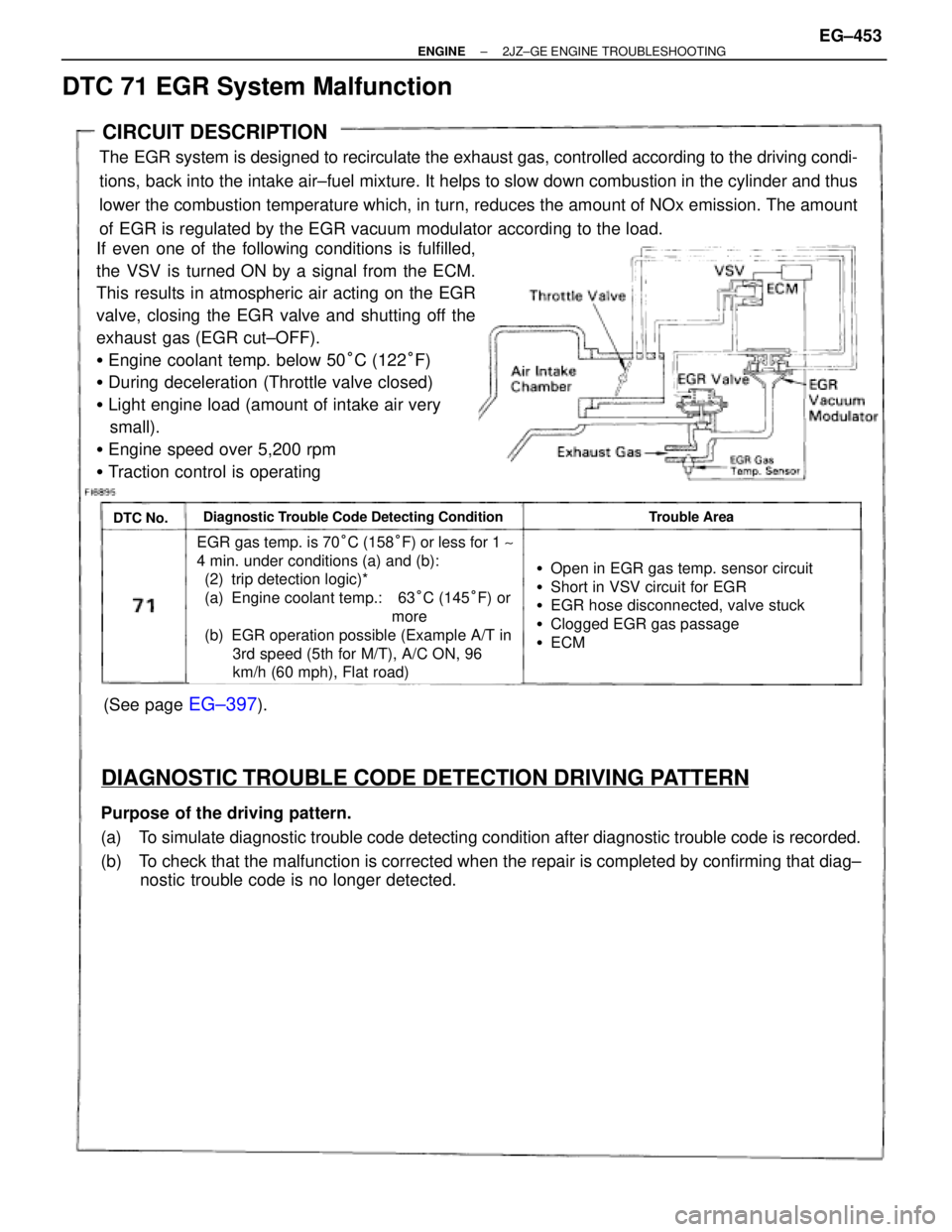
CIRCUIT DESCRIPTION
The EGR system is designed to recirculate the exhaust gas, controlled according to the driving condi-
tions, back into the intake air±fuel mixture. It helps to slow down combustion in the cylinder and thus
lower the combustion temperature which, in turn, reduces the amount of NOx emission. The amount
of EGR is regulated by the EGR vacuum modulator according to the load.
If even one of the following conditions is fulfilled,
the VSV is turned ON by a signal from the ECM.
This results in atmospheric air acting on the EGR
valve, closing the EGR valve and shutting off the
exhaust gas (EGR cut±OFF).
�Engine coolant temp. below 50°C (122°F)
�During deceleration (Throttle valve closed)
�Light engine load (amount of intake air very
small).
�Engine speed over 5,200 rpm
�Traction control is operating
DTC No.Diagnostic Trouble Code Detecting ConditionTrouble Area
EGR gas temp. is 70°C (158°F) or less for 1 ~
4 min. under conditions (a) and (b):
(2) trip detection logic)*
(a) Engine coolant temp.: 63°C (145°F) or
more
(b) EGR operation possible (Example A/T in
3rd speed (5th for M/T), A/C ON, 96
km/h (60 mph), Flat road)
�Open in EGR gas temp. sensor circuit
�Short in VSV circuit for EGR
�EGR hose disconnected, valve stuck
�Clogged EGR gas passage
�ECM
DIAGNOSTIC TROUBLE CODE DETECTION DRIVING PATTERN
Purpose of the driving pattern.
(a) To simulate diagnostic trouble code detecting condition after diagnostic trouble code is recorded.
(b) To check that the malfunction is corrected when the repair is completed by confirming that diag±
nostic trouble code is no longer detected.
DTC 71 EGR System Malfunction
± ENGINE2JZ±GE ENGINE TROUBLESHOOTINGEG±453
Page 245 of 878

IF VEHICLE IS EQUIPPED WITH MOBILE
RADIO SYSTEM (HAM, CB, ETC.)
If the vehicle is equipped with a mobile communication sys-
tem, refer to the precaution in the IN section.
AIR INDUCTION SYSTEM
1. Separation of the engine oil dipstick, oil filler cap, PCV hose,
etc. may cause the engine to run out of tune.
2. Disconnection, looseness or cracks in the parts of the air
induction system between the throttle body and cylinder
head will cause air suction and cause the engine to run out
of tune.
ELECTRONIC CONTROL SYSTEM
1. Before removing SFI wiring connectors, terminals, etc., first
disconnect the power by either turning the ignition switch
OFF or disconnecting the negative (±) terminal cable from the
battery.
HINT: Always check the diagnostic trouble code before dis-
connecting the negative (±) terminal cable from the battery.
2. When installing the battery, be especially careful not to
incorrectly connect the positive (+) and negative (±) cables.
3. Do not permit parts to receive a severe impact during removal
or installation. Handle all SFI parts carefully, especially the
ECM.
4. Do not be careless during troubleshooting as there are
numerous transistor circuits and even slight terminal contact
can cause further troubles.
5. Do not open the ECM cover.
6. When inspecting during rainy weather, take care to prevent
entry of water. Also, when washing the engine compartment,
prevent water from getting on the SFI parts and wiring
connectors.
7. Parts should be replaced as an assembly.
8. Care is required when pulling out and inserting wiring
connectors.
(a) Release the lock and pull out the connector, pulling on the
connectors.
(b) Fully insert the connector and check that it is locked.
± ENGINESFI SYSTEM (2JZ±GTE)EG±261
Page 256 of 878
FUEL PRESSURE REGULATOR
INSTALLATION
1. INSTALL FUEL PRESSURE REGULATOR
(a) Apply a light coat of gasoline to a new O±ring, and install it
to the pressure regulator.
(b) Attach the pressure regulator to the delivery pipe.
(c) Check that the pressure regulator rotates smoothly.
NOTICE: If it does not rotate smoothly, the O±ring may be
pinched, so remove the pressure regulator and do steps (b)
and (c) above again.
(d) Install the pressure regulator with the 2 bolts.
Torque: 8.8 NVm (90 kgfVcm, 78 in.Vlbf)
2. CONNECT FUEL RETURN PIPE TO FUEL PRESSURE
REGULATOR
Install the return pipe with 2 new gaskets and the union bolt.
Torque: 27 NVm (280 kgfVcm, 20 ftVlbf)
3. CONNECT VACUUM SENSING HOSE TO FUEL
PRESSURE REGULATOR
4. INSTALL THROTTLE BODY
(See throttle body installation)
5. CHECK FOR FUEL LEAKS
(See item 5 in fuel system in precaution) EG±272
± ENGINESFI SYSTEM (2JZ±GTE)
Page 316 of 878

IF VEHICLE IS EQUIPPED WITH MOBIL
RADIO SYSTEM (HAM, CB, ETC.)
If the vehicle is equipped with a mobile communication sys-
tem, refer to the precaution in the IN section.
AIR INDUCTION SYSTEM
1. Separation of the engine oil dipstick, oil filler cap, PCV hose,
etc. may cause the engine to run out of tune.
2. Disconnection, looseness or cracks in the parts of the air
induction system between the throttle body and cylinder
head will cause air suction and cause the engine to run out
of tune.
ELECTRONIC CONTROL SYSTEM
1. Before removing SFI wiring connectors, terminals, etc., first
disconnect the power by either turning the ignition switch
OFF or disconnecting the negative (±) terminal cable from the
battery.
HINT: Always check the diagnostic trouble code before dis-
connecting the negative (±) terminal cable from the battery.
2. When installing the battery, be especially careful not to
incorrectly connect the positive (+) and negative (±) cables.
3. Do not permit parts to receive a severe impact during removal
or installation. Handle all SFI parts carefully, especially the
ECM.
4. Do not be careless during troubleshooting as there are
numerous transistor circuits and even slight terminal contact
can cause further troubles.
5. Do not open the ECM cover.
6. When inspecting during rainy weather, take care to prevent
entry of water. Also, when washing the engine compartment,
prevent water from getting on the SFI parts and wiring
connectors.
7. Parts should be replaced as an assembly.
8. Care is required when pulling out and inserting wiring
connectors.
(a) Release the lock and pull out the connector, pulling on the
connectors.
(b) Fully insert the connector and check that it is locked. EG±190
± ENGINESFI SYSTEMS (2JZ±GE)
Page 327 of 878
FUEL PRESSURE REGULATOR
INSTALLATION
1. INSTALL FUEL PRESSURE REGULATOR
(a) Apply a light coat of gasoline to a new O±ring, and install it
to the pressure regulator.
(b) Attach the pressure regulator to the delivery pipe.
(c) Check that the pressure regulator rotates smoothly.
NOTICE: If it does not rotate smoothly, the O±ring may be
pinched, so remove the pressure regulator and do steps (b)
and (c) above again.
(d) Install the pressure regulator with the 2 bolts.
Torque: 8.8 NVm (90 kgfVcm, 78 in.Vlbf)
2. CONNECT FUEL RETURN PIPE TO FUEL PRESSURE
REGULATOR
Install the return pipe with 2 new gaskets and the union bolt.
Torque: 27 NVm (280 kgfVcm, 20 ftVlbf)
3. CONNECT VACUUM SENSING HOSE TO FUEL
PRESSURE REGULATOR
4. CHECK FOR FUEL LEAKS
(See item 5 in fuel system in precaution)
± ENGINESFI SYSTEM (2JZ±GE)EG±201
Page 395 of 878
Valve clearance (Cold):
Intake
.15±0.25 mm (0.006±0.010 in.)
Exhaust
.25±0.35 mm (0.010±0.014 in.)
(b) Turn the crankshaft pulley 1 revolution (360°), and align the
groove with timing mark ºOº of the No.1 timing belt cover.
(c) Check only the valves indicated as shown. Measure the valve
clearance. (See procedure in step (a))
6. ADJUST VALVE CLEARANCE
(a) Remove the adjusting shim.
wTurn the camshaft so that the cam lobe for the valve to
be adjusted faces up.
wTurn the valve lifter with a screwdriver so that the
notches are perpendicular to the camshaft.
wUsing SST (A), hold the camshaft as shown in the
illustration.
SST 09248±55040 (09248±05410)
wUsing SST (A), press down the valve lifter and place
SST (B) between the camshaft and valve lifter. Remove
SST (A).
SST 09248±55040 (09248±05410, 09248±05420)
HINT:
wApply SST (B) at slight angle on the side marked with
º7º, at the position shown in the illustration. EG±12
± ENGINEENGINE MECHANICAL
Page 402 of 878
3. CHECK IDLE SPEED
(a) Race the engine speed at 2,500 rpm for approx. 90 seconds.
(b) Check the idle speed.
Idle speed:
700 + 50 rpm
4. ADJUST IGNITION TIMING
(a) Using SST, connect terminals TE1 and E1 of the DLC 1.
SST 09843±18020
(b) Using a timing light, check the ignition timing.
Ignition timing:
10 + 2° BTDC @ idle
(Transmission in neutral position)
(c) Loosen the nut, and adjust by turning the distributor.
Ignition timing:
10° BTDC @ idle
(Transmission in neutral position)
(d) Tighten the nut, and recheck the ignition timing.
Torque: 19 NVm (195 kgfVcm, 14 ftVlbf)
(e) Remove the SST from the DLC1.
SST 09843±18020
5. FURTHER CHECK IGNITION TIMING
Ignition timing:
7±19° BTDC @ idle
(Transmission in neutral position)
HINT: The timing mark moves in a range between 75 and 195.
6. DISCONNECT TACHOMETER AND TIMING LIGHT
± ENGINEENGINE MECHANICALEG±19