Page 169 of 878

DTC 14 Ignition Signal Circuit
CIRCUIT DESCRIPTION
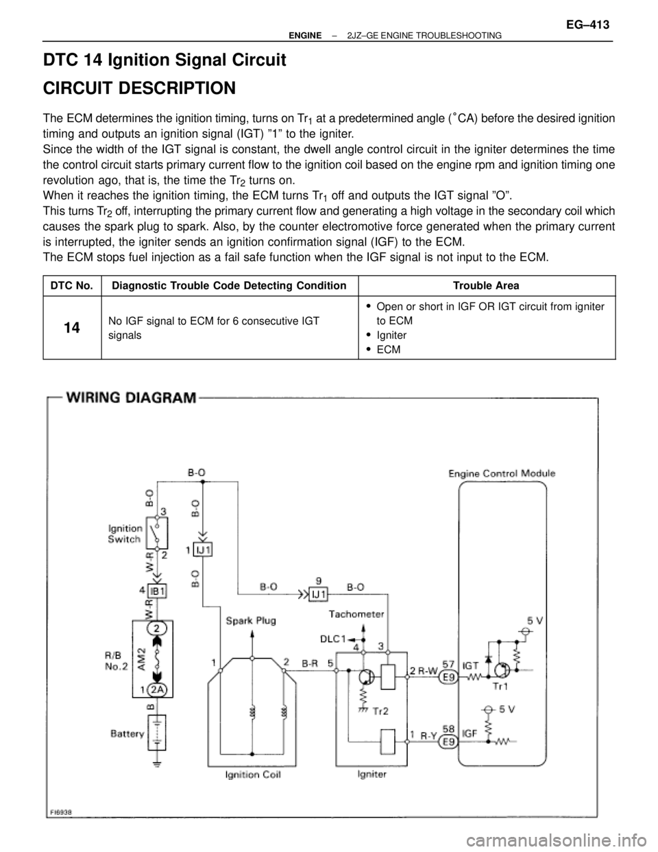
The ECM determines the ignition timing, turns on Tr1 at a predetermined angle (°CA) before the desired ignition
timing and outputs an ignition signal (IGT) º1º to the igniter.
Since the width of the IGT signal is constant, the dwell angle control circuit in the igniter determines the time
the control circuit starts primary current flow to the ignition coil based on the engine rpm and ignition timing one
revolution ago, that is, the time the Tr
2 turns on.
When it reaches the ignition timing, the ECM turns Tr
1 off and outputs the IGT signal ºOº.
This turns Tr
2 off, interrupting the primary current flow and generating a high voltage in the secondary coil which
causes the spark plug to spark. Also, by the counter electromotive force generated when the primary current
is interrupted, the igniter sends an ignition confirmation signal (IGF) to the ECM.
The ECM stops fuel injection as a fail safe function when the IGF signal is not input to the ECM.
����� �����DTC No.���������������� ����������������Diagnostic Trouble Code Detecting Condition����������������� �����������������Trouble Area����� �
���� �����
14
���������������� �
��������������� ���������������� No IGF signal to ECM for 6 consecutive IGT
����������������� �
���������������� ������������������Open or short in IGF OR IGT circuit from igniter
to ECM
����� �
���� �����
14���������������� �
��������������� ����������������
No IGF signal to ECM for 6 consecutive IGT
signals����������������� �
���������������� �����������������
to ECM
�Igniter
�ECM
± ENGINE2JZ±GE ENGINE TROUBLESHOOTINGEG±413
Page 172 of 878
Check ignition coil.
Disconnect ignition coil connector.
(1) Check primary coil.
Measure resistance between terminals of ignition coil
connector.
(2) Check secondary coil.
Measure resistance between terminal � of ignition coil
connector and high±tension terminal.
Repair or replace harness or connector.
Check for open and short in harness and connector between ignitioin switch
and ignition coil, ignition coil and igniter (See page
IN±30).
ªColdº is from Ð 10°C (14°F) to 50°C (122°F) and
ªHotº is from 50°C (122°F) to 100°C (212°F).
Replace ignition coil.
Replace igniter.
Resistance
Primary Coil
Secondary
Coil
EG±416± ENGINE2JZ±GE ENGINE TROUBLESHOOTING
Page 194 of 878

DTC 31 Volume Air Flow Meter Circuit
CIRCUIT DESCRIPTION
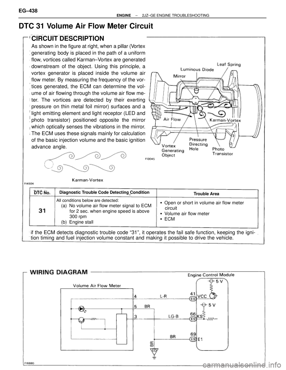
As shown in the figure at right, when a pillar (Vortex
generating body is placed in the path of a uniform
flow, vortices called Karman±Vortex are generated
downstream of the object. Using this principle, a
vortex generator is placed inside the volume air
flow meter. By measuring the frequency of the vor-
tices generated, the ECM can determine the vol-
ume of air flowing through the volume air flow me-
ter. The vortices are detected by their exerting
pressure on thin metal foil mirror) surfaces and a
light emitting element and light receptor (LED and
photo transistor) positioned opposite the mirror
which optically senses the vibrations in the mirror.
The ECM uses these signals mainly for calculation
of the basic injection volume and the basic ignition
advance angle.
DTC No.Diagnostic Trouble Code Detecting ConditionTrouble Area
All conditions below are detected:
(a) No volume air flow meter signal to ECM
for 2 sec. when engine speed is above
300 rpm
(b) Engine stall �Open or short in volume air flow meter
circuit
�Volume air flow meter
�ECM
if the ECM detects diagnostic trouble code ª31º, it operates the fail safe function, keeping the igni-
tion timing and fuel injection volume constant and making it possible to drive the vehicle. EG±438
± ENGINE2JZ±GE ENGINE TROUBLESHOOTING
Page 221 of 878
ECM Power Source Circuit
CIRCUIT DESCRIPTION
When the ignition switch is turned on, battery
voltage is applied to the terminals IGSW of the
ECM, and the main relay control circuit in the
ECM sends a signal to the terminal M±REL of the
ECM, switching on the main relay. This signal
causes current to flow to the coil, closing the con-
tacts of the main relay and supplying power to the
terminal +B of the ECM.
If the ignition switch is turned off, the ECM contin-
ues to switch on the main relay for a maximum of
2 seconds for the initial setting of the IAC valve.
± ENGINE2JZ±GE ENGINE TROUBLESHOOTINGEG±465
Page 231 of 878
CIRCUIT DESCRIPTION
The IAC valve is situated on the intake chamber. Intake
air bypassing the throttle valve is directed to the IAC
valve through a passage.
A step motor is built into the IAC valve. It consists of 4
coils, a magnetic rotor, valve shaft and valve.
When current flows to the coils due to signals from the
ECM, the rotor turns and moves the valve shaft forward
or backward, changing the clearance between the
valve and the valve seat.
In this way the intake air volume bypassing the throttle
valve is regulated, controlling the engine speed.
There are 125 possible positions to which the valve can
be opened.
�With the engine idling measure wave forms
between terminals ISC1, ISC2, ISC3, ISC4
and E01 of engine control module when
A/C switch ON or OFF.
HINT:
The correct waveforms are as shown.
INSPECTION USING OSCILLOSCOPE
IAC Valve Circuit
± ENGINE2JZ±GE ENGINE TROUBLESHOOTINGEG±475
Page 242 of 878
SFI SYSTEM (2JZ±GTE)
PREPARATION
SST (SPECIAL SERVICE TOOLS)
09205±76030 Cylinder Head Setting Bolt
Tightening Adaptor
09268±41045Injection Measuring Tool Set
(09268±41070)No.4 Union
(90405±09015)No.1 Union
09268±45012 EFI Fuel Pressure Gauge
ECT sensor
09612±24014 Steering Gear Housing Overhaul
Tool Set
(09617±24011) Steering Rack Wrench
09631±22020 Power Steering Hose Nut
14 x 17 mm Wrench Set
09808±14010Fuel Sender Gauge Tool Assy
09816±30010 Oil Pressure Switch Socket
09842±30080 Wiring ªEº EFI Inspection
Knock sensor
Fuel pressure pulsation damper
09843±18020 Diagnosis Check Wire
Injector
Fuel line flare nut
EG±258± ENGINESFI SYSTEM (2JZ±GTE)
Page 244 of 878

PRECAUTION
1. Before working on the fuel system, disconnect the
negative (±) terminal cable from the battery.
HINT: Any diagnostic trouble code retained by the computer
will be erased when the negative (±) terminal cable is discon-
nected.
Therefore, if necessary, read the diagnosis before discon-
necting the negative (±) terminal cable from the battery.
2. Do not smoke or work near an open flame when working
on the fuel system.
3. Keep gasoline away from rubber or leather parts.
MAINTENANCE PRECAUTIONS
1. PRECAUTION WHEN CONNECTING GAUGE
(a) Use ba tte ry as th e po we r so u rce fo r th e timin g lig h t,
tachometer, etc.
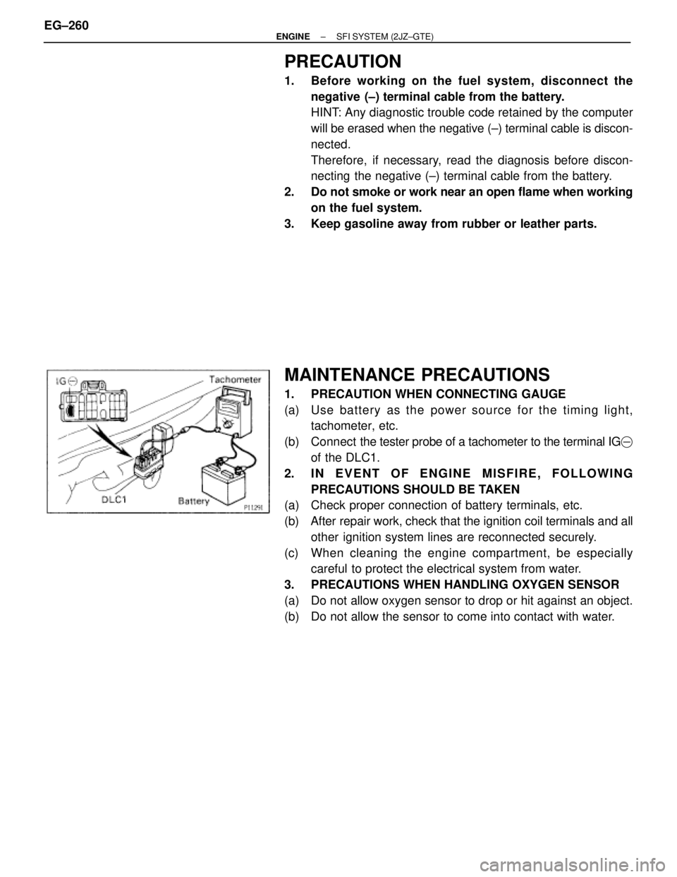
(b) Connect the tester probe of a tachometer to the terminal IG�
of the DLC1.
2. IN EVENT OF ENGINE MISFIRE, FOLLOWING
PRECAUTIONS SHOULD BE TAKEN
(a) Check proper connection of battery terminals, etc.
(b) After repair work, check that the ignition coil terminals and all
other ignition system lines are reconnected securely.
(c) When cleaning the engine compartment, be especially
careful to protect the electrical system from water.
3. PRECAUTIONS WHEN HANDLING OXYGEN SENSOR
(a) Do not allow oxygen sensor to drop or hit against an object.
(b) Do not allow the sensor to come into contact with water. EG±260
± ENGINESFI SYSTEM (2JZ±GTE)
Page 245 of 878

IF VEHICLE IS EQUIPPED WITH MOBILE
RADIO SYSTEM (HAM, CB, ETC.)
If the vehicle is equipped with a mobile communication sys-
tem, refer to the precaution in the IN section.
AIR INDUCTION SYSTEM
1. Separation of the engine oil dipstick, oil filler cap, PCV hose,
etc. may cause the engine to run out of tune.
2. Disconnection, looseness or cracks in the parts of the air
induction system between the throttle body and cylinder
head will cause air suction and cause the engine to run out
of tune.
ELECTRONIC CONTROL SYSTEM
1. Before removing SFI wiring connectors, terminals, etc., first
disconnect the power by either turning the ignition switch
OFF or disconnecting the negative (±) terminal cable from the
battery.
HINT: Always check the diagnostic trouble code before dis-
connecting the negative (±) terminal cable from the battery.
2. When installing the battery, be especially careful not to
incorrectly connect the positive (+) and negative (±) cables.
3. Do not permit parts to receive a severe impact during removal
or installation. Handle all SFI parts carefully, especially the
ECM.
4. Do not be careless during troubleshooting as there are
numerous transistor circuits and even slight terminal contact
can cause further troubles.
5. Do not open the ECM cover.
6. When inspecting during rainy weather, take care to prevent
entry of water. Also, when washing the engine compartment,
prevent water from getting on the SFI parts and wiring
connectors.
7. Parts should be replaced as an assembly.
8. Care is required when pulling out and inserting wiring
connectors.
(a) Release the lock and pull out the connector, pulling on the
connectors.
(b) Fully insert the connector and check that it is locked.
± ENGINESFI SYSTEM (2JZ±GTE)EG±261