Page 43 of 878
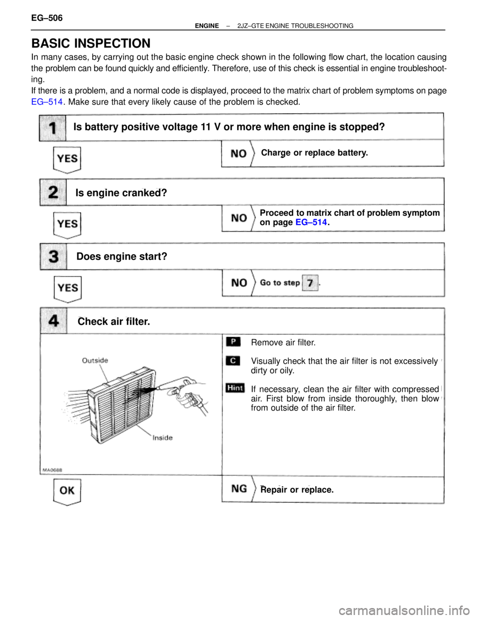
BASIC INSPECTION
In many cases, by carrying out the basic engine check shown in the following flow chart, the location causing
the problem can be found quickly and efficiently. Therefore, use of this check is essential in engine troubleshoot-
ing.
If there is a problem, and a normal code is displayed, proceed to the matrix chart of problem symptoms on page
EG±514. Make sure that every likely cause of the problem is checked.
Is battery positive voltage 11 V or more when engine is stopped?
Is engine cranked?
Does engine start?
Check air filter.
Charge or replace battery.
Proceed to matrix chart of problem symptom
on page EG±514.
Repair or replace.
Remove air filter.
Visually check that the air filter is not excessively
dirty or oily.
If necessary, clean the air filter with compressed
air. First blow from inside thoroughly, then blow
from outside of the air filter.
Charge or replace battery.
Is battery positive voltage 11 V or more when engine is stopped?
EG±506± ENGINE2JZ±GTE ENGINE TROUBLESHOOTING
Page 44 of 878
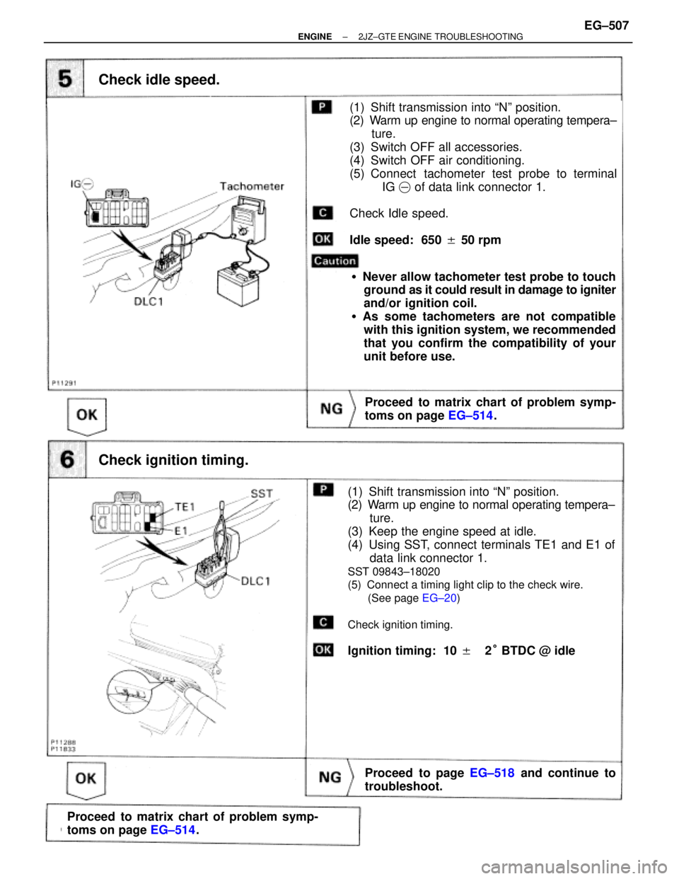
(See page EG±20)
Check idle speed.
Proceed to matrix chart of problem symp-
toms on page EG±514.
(1) Shift transmission into ªNº position.
(2) Warm up engine to normal operating tempera±
ture.
(3) Switch OFF all accessories.
(4) Switch OFF air conditioning.
(5) Connect tachometer test probe to terminal
IG� of data link connector 1.
Check Idle speed.
Idle speed: 650 � 50 rpm
�Never allow tachometer test probe to touch
ground as it could result in damage to igniter
and/or ignition coil.
�As some tachometers are not compatible
with this ignition system, we recommended
that you confirm the compatibility of your
unit before use.
Check ignition timing.
(1) Shift transmission into ªNº position.
(2) Warm up engine to normal operating tempera±
ture.
(3) Keep the engine speed at idle.
(4) Using SST, connect terminals TE1 and E1 of
data link connector 1.
SST 09843±18020
(5) Connect a timing light clip to the check wire.
(See page EG±20)
Check ignition timing.
Ignition timing: 10 ��2° BTDC @ idle
Proceed to matrix chart of problem symp-
toms on page EG±514.
Proceed to page EG±518 and continue to
troubleshoot.
± ENGINE2JZ±GTE ENGINE TROUBLESHOOTINGEG±507
Page 45 of 878
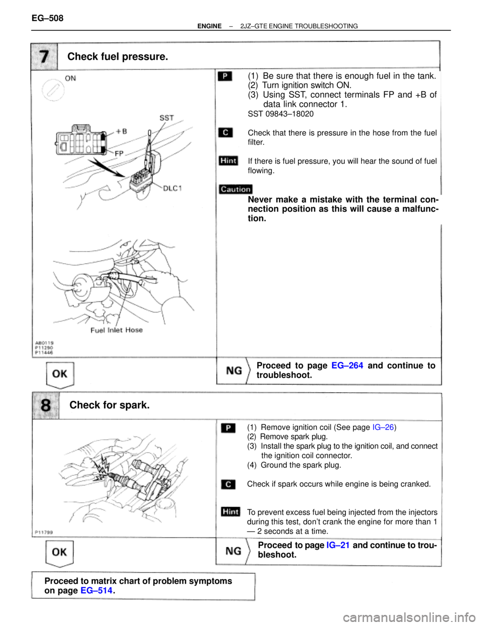
(See page
IG±26)
Check fuel pressure.
Proceed to page EG±264 and continue to
troubleshoot.
(1) Be sure that there is enough fuel in the tank.
(2) Turn ignition switch ON.
(3) Using SST, connect terminals FP and +B of
data link connector 1.
SST 09843±18020
Check that there is pressure in the hose from the fuel
filter.
If there is fuel pressure, you will hear the sound of fuel
flowing.
Never make a mistake with the terminal con-
nection position as this will cause a malfunc-
tion.
Check for spark.
Proceed to page IG±21 and continue to trou-
bleshoot.
Proceed to matrix chart of problem symptoms
on page EG±514.
(1) Remove ignition coil (See page IG±26)
(2) Remove spark plug.
(3) Install the spark plug to the ignition coil, and connect
the ignition coil connector.
(4) Ground the spark plug.
Check if spark occurs while engine is being cranked.
To prevent excess fuel being injected from the injectors
during this test, don't crank the engine for more than 1
Ð 2 seconds at a time.
EG±508± ENGINE2JZ±GTE ENGINE TROUBLESHOOTING
Page 51 of 878
Suspect area
See page
Symptom
Engine does not crank
No initial combustion
No complete combustion
Engine cranks normally
Cold engine
Hot engine
Incorrect first idle
High engine idle speed
Low engine idle speed
Rough idling
Hunting
Hesitation/Poor acceleration
Muffler explosion (after fire)
Surging
Soon after starting
After accelerator pedal depressed
After accelerator pedal released
During A/C operation
When shifting N to D
Does not
start
Difficult to
start
Poor Idling
Engine Stall
Poor
Driveability
Back up power source circuitECM power source circuitPark/neutral position switch circuitSwitch condition signal circuitEGR systemStarter signal circuitMass air flow meter circuitInjector circuitIAC valve circuitFuel pump control circuitA/C signal circuit (Compressor circuit)Turbo control circuitVSV circuit for fuel Pressure ControlCompressionSpark plugIgnition signal circuit (Spark test)Starter and Starter relayIgnition coilEngine control module (ECM)Theft deterrent ECUA/T faulty
EG±544EG±559EG±564EG±571EG±574EG±576EG±581EG±583EG±586EG±568EG±595EG±589AC±62ST±3
,
12
IG±21IG±23IG±22EG±9AT2±101BE±123IN±35
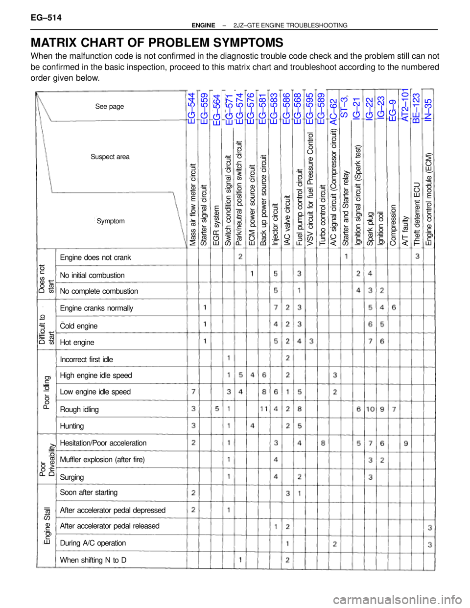
MATRIX CHART OF PROBLEM SYMPTOMS
When the malfunction code is not confirmed in the diagnostic trouble code check and the problem still can not
be confirmed in the basic inspection, proceed to this matrix chart and troubleshoot according to the numbered
order given below. EG±514
± ENGINE2JZ±GTE ENGINE TROUBLESHOOTING
Page 52 of 878
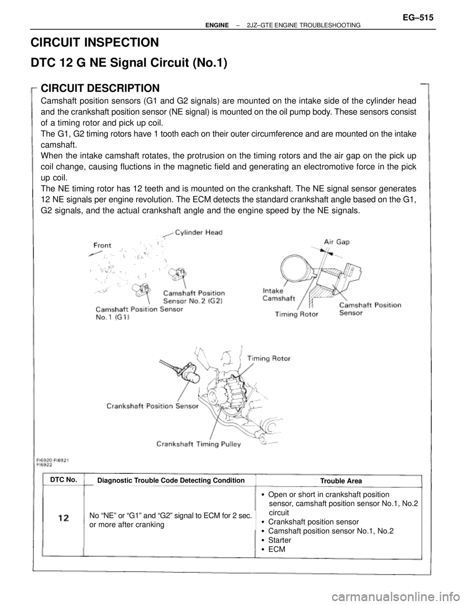
CIRCUIT DESCRIPTION
Camshaft position sensors (G1 and G2 signals) are mounted on the intake side of the cylinder head
and the crankshaft position sensor (NE signal) is mounted on the oil pump body. These sensors consist
of a timing rotor and pick up coil.
The G1, G2 timing rotors have 1 tooth each on their outer circumference and are mounted on the intake
camshaft.
When the intake camshaft rotates, the protrusion on the timing rotors and the air gap on the pick up
coil change, causing fluctions in the magnetic field and generating an electromotive force in the pick
up coil.
The NE timing rotor has 12 teeth and is mounted on the crankshaft. The NE signal sensor generates
12 NE signals per engine revolution. The ECM detects the standard crankshaft angle based on the G1,
G2 signals, and the actual crankshaft angle and the engine speed by the NE signals.
DTC No.Diagnostic Trouble Code Detecting ConditionTrouble Area
No ªNEº or ªG1º and ªG2º signal to ECM for 2 sec.
or more after cranking
�Open or short in crankshaft position
sensor, camshaft position sensor No.1, No.2
circuit
�Crankshaft position sensor
�Camshaft position sensor No.1, No.2
�Starter
�ECM
CIRCUIT INSPECTION
DTC 12 G NE Signal Circuit (No.1)
± ENGINE2JZ±GTE ENGINE TROUBLESHOOTINGEG±515
Page 56 of 878
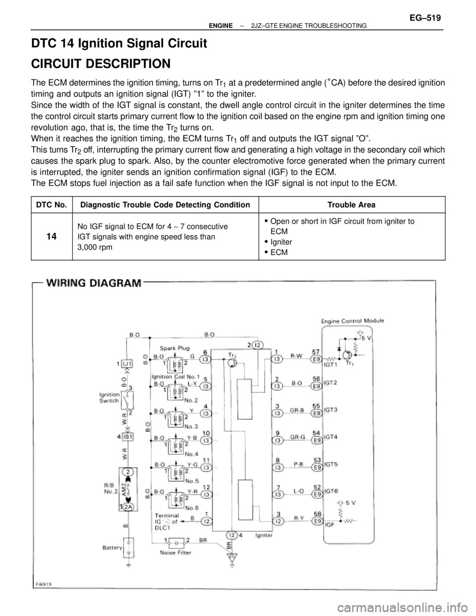
DTC 14 Ignition Signal Circuit
CIRCUIT DESCRIPTION
The ECM determines the ignition timing, turns on Tr1 at a predetermined angle (°CA) before the desired ignition
timing and outputs an ignition signal (IGT) º1º to the igniter.
Since the width of the IGT signal is constant, the dwell angle control circuit in the igniter determines the time
the control circuit starts primary current flow to the ignition coil based on the engine rpm and ignition timing one
revolution ago, that is, the time the Tr
2 turns on.
When it reaches the ignition timing, the ECM turns Tr
1 off and outputs the IGT signal ºOº.
This turns Tr
2 off, interrupting the primary current flow and generating a high voltage in the secondary coil which
causes the spark plug to spark. Also, by the counter electromotive force generated when the primary current
is interrupted, the igniter sends an ignition confirmation signal (IGF) to the ECM.
The ECM stops fuel injection as a fail safe function when the IGF signal is not input to the ECM.
����� �����DTC No.���������������� ����������������Diagnostic Trouble Code Detecting Condition����������������� �����������������Trouble Area����� �
���� �
���� �
���� �����
14
���������������� �
��������������� �
��������������� �
��������������� ����������������
No IGF signal to ECM for 4 ~ 7 consecutive
IGT signals with engine speed less than
3,000 rpm
����������������� �
���������������� �
���������������� �
���������������� �����������������
�Open or short in IGF circuit from igniter to
ECM
�Igniter
�ECM
± ENGINE2JZ±GTE ENGINE TROUBLESHOOTINGEG±519
Page 57 of 878
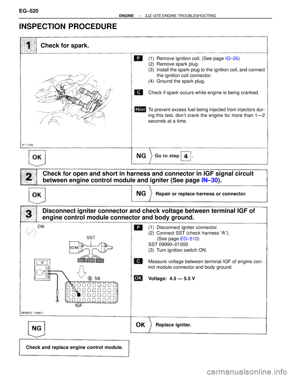
Check for spark.
(1) Remove ignition coil. (See page IG±26)
(2) Remove spark plug.
(3) Install the spark plug to the ignition coil, and connect
the ignition coil connector.
(4) Ground the spark plug.
Check if spark occurs while engine is being cranked.
To prevent excess fuel being injected from injectors dur-
ing this test, don't crank the engine for more than 1Ð2
seconds at a time.
Check for open and short in harness and connector in IGF signal circuit
between engine control module and igniter (See page IN±30).
Repair or replace harness or connector.
Replace igniter.
Check and replace engine control module.
Disconnect igniter connector and check voltage between terminal IGF of
engine control module connector and body ground.
(1) Disconnect igniter connector.
(2) Connect SST (check harness ªAº).
(See page EG±510)
SST 09990±01000
(3) Turn ignition switch ON.
Measure voltage between terminal IGF of engine con-
trol module connector and body ground.
Voltage: 4.5 Ð 5.5 V
INSPECTION PROCEDURE
EG±520± ENGINE2JZ±GTE ENGINE TROUBLESHOOTING
Page 59 of 878
Check for open and short in harness and connector between ignition
switch and ignition coil, ignition coil and igniter (See page IN±30).
Disconnect ignition coil connector.
(See page IG±23)
Measure resistance between terminals of ignition coil
connector.
Repair or replace harness or connector.
Check ignition coil.
ªColdº is from Ð 10°C (14°F) to 50°C (122°F) and ªHotº is
from 50°C (122°F) to 100°C (212°F).
Replace ignition coil.
Replace igniter.
EG±522± ENGINE2JZ±GTE ENGINE TROUBLESHOOTING