Page 113 of 878
ECM Power Source Circuit
CIRCUIT DESCRIPTION
When the ignition switch is turned on, battery volt-
age is applied to the terminal IGSW of the ECM,
and the main relay control circuit in the ECM sends
a signal to the terminal M±REL of the ECM, switch-
ing on the main relay. This signal causes current to
flow to the coil, closing the contacts of the main
relay and supplying power to the terminal + B of the
ECM.
If the ignition switch is turned off, the ECM contin-
ues to switch on the main relay for a maximum of
2 seconds for the initial setting of the IAC valve. EG±576
± ENGINE2JZ±GTE ENGINE TROUBLESHOOTING
Page 123 of 878
CIRCUIT DESCRIPTION
The IAC valve is situated on the intake air chamber In-
take air bypassing the throttle valve is directed to the
IAC valve through a passage.
A step motor is built into the IAC valve. It consists of 4
coils, a magnetic rotor, valve shaft and a valve.
When the current flows to the coils due to signals from
the ECM, the rotor turns and moves the valve shaft for-
ward or backward, changing the clearance between
the valve and the valve seat.
In this way the intake air volume bypassing the throttle
valve is regulated, controlling the engine speed.
There are 125 possible positions to which the valve can
be opened.
�With the engine idling measure wave forms
between terminals ISC1, ISC2, ISC3,
ISC4 and E01 of engine control module
when A/C switch ON or OFF.
HINT:
The correct waveforms are as shown.
INSPECTION USING OSCILLOSCOPEReference
IAC Valve Circuit
EG±586± ENGINE2JZ±GTE ENGINE TROUBLESHOOTING
Page 156 of 878
BASIC INSPECTION
In many cases, by carrying out the basic engine check shown in the following flow chart, the location causing
the problem can be found quickly and efficiently. Therefore, use of this check is essential in engine trouble-
shooting.
If there is a problem, and a normal code is displayed, proceed to the matrix chart of problem symptoms on page
EG±408. Make sure that every likely cause of the problem is checked.
EG±408.
Is battery positive voltage 11 V or more when engine is stopped?
Is engine cranked?
Does engine start?
Check air filter.
Charge or replace battery.
Proceed to matrix chart of problem symptoms
on page EG±408.
Repair or replace.
Remove air filter.
Visually check that the air filter is not excessive dirty or
oily.
If necessary, clean the air filter with compressed air. First
blow from inside thoroughly, then blow from outside of
the air filter.
EG±400± ENGINE2JZ±GE ENGINE TROUBLESHOOTING
Page 157 of 878

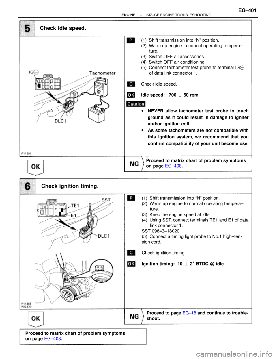
Check idle speed.
Check ignition timing.
Check idle speed.
(1) Shift transmission into ªNº position.
(2) Warm up engine to normal operating tempera±
ture.
(3) Switch OFF all accessories.
(4) Switch OFF air conditioning.
(5) Connect tachometer test probe to terminal IG�
of data link connector 1.
Check idle speed.
Idle speed: 700 � 50 rpm
wNEVER allow tachometer test probe to touch
ground as it could result in damage to igniter
and/or ignition coil.
wAs some tachometers are not compatible with
this ignition system, we recommend that you
confirm compatibility of your unit become use.
Proceed to matrix chart of problem symptoms
on page EG±408.
Proceed to page EG±18 and continue to trouble-
shoot.
Proceed to matrix chart of problem symptoms
on page EG±408.
(1) Shift transmission into ªNº position.
(2) Warm up engine to normal operating tempera±
ture.
(3) Keep the engine speed at idle.
(4) Using SST, connect terminals TE1 and E1 of data
link connector 1.
SST 09843±18020
(5) Connect a timing light probe to No.1 high±ten-
sion cord.
Check ignitiion timing.
Ignition timing: 10 � 2° BTDC @ idle
± ENGINE2JZ±GE ENGINE TROUBLESHOOTINGEG±401
Page 164 of 878

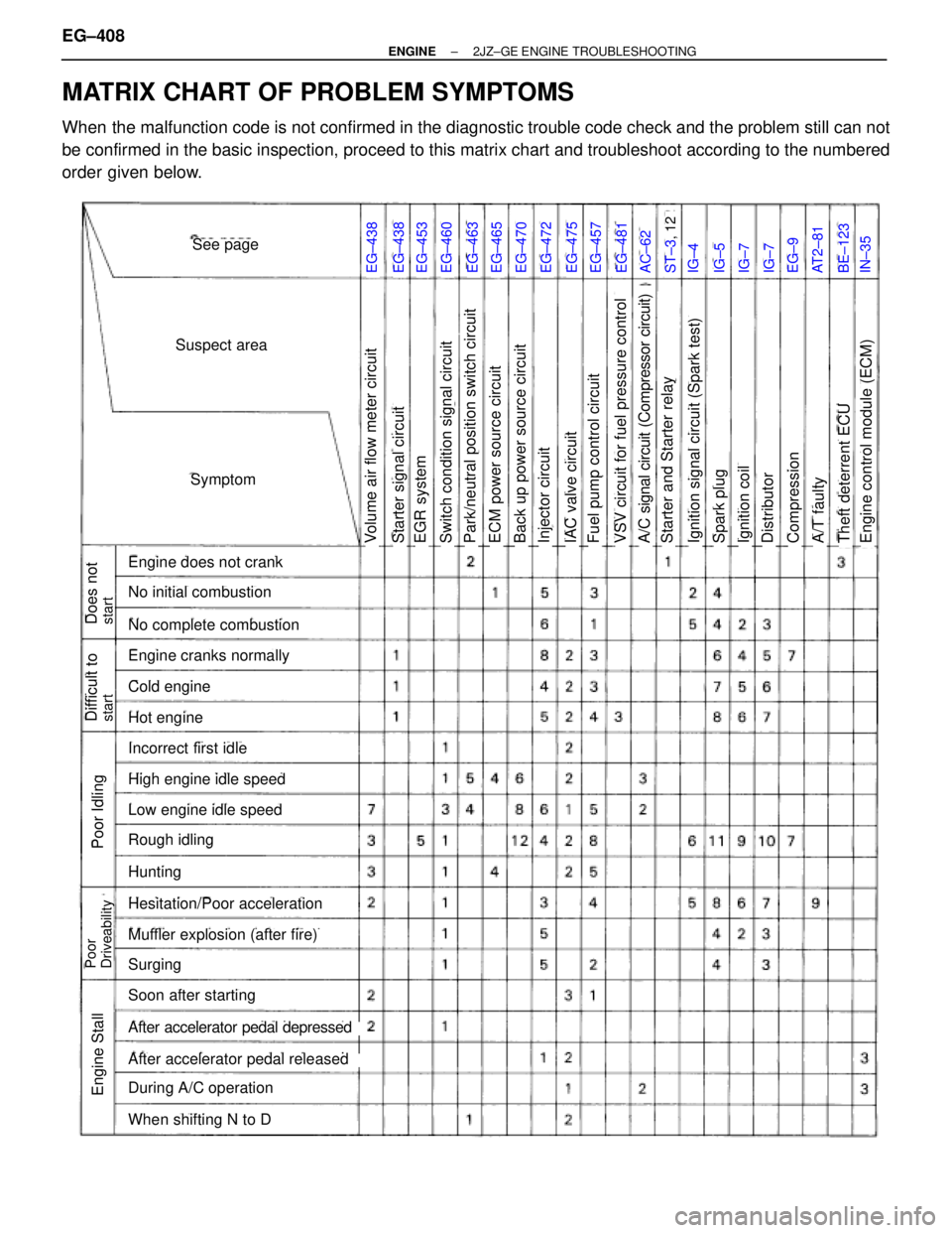
MATRIX CHART OF PROBLEM SYMPTOMS
When the malfunction code is not confirmed in the diagnostic trouble code check and the problem still can not
be confirmed in the basic inspection, proceed to this matrix chart and troubleshoot according to the numbered
order given below.
EG±438EG±438EG±453EG±460EG±463EG±465EG±470EG±472EG±475EG±457EG±481AC±62ST±3, 12IG±4IG±5IG±7IG±7EG±9AT2±81BE±123IN±35
See page
Suspect area
Symptom
Engine does not crank
No initial combustion
No complete combustion
Engine cranks normally
Cold engine
Hot engine
Incorrect first idle
High engine idle speed
Low engine idle speed
Rough idling
Hunting
Hesitation/Poor acceleration
Muffler explosion (after fire)
Surging
Soon after starting
After accelerator pedal depressed
After accelerator pedal released
During A/C operation
When shifting N to D
Does notstart
Difficult tostart
Poor Idling
Poor
Driveability
Engine Stall
Volume air flow meter circuitECM power source circuitPark/neutral position switch circuitSwitch condition signal circuitEGR systemStarter signal circuitStarter and Starter relayA/C signal circuit (Compressor circuit)VSV circuit for fuel pressure controlFuel pump control circuitIAC valve circuitInjector circuitBack up power source circuitIgnition coilSpark plugIgnition signal circuit (Spark test)CompressionA/T faultyDistributorEngine control module (ECM)Theft deterrent ECU
EG±408± ENGINE2JZ±GE ENGINE TROUBLESHOOTING
Page 165 of 878
CIRCUIT INSPECTION
DTC 12 G NE Signal Circuit (No.1)
CIRCUIT DESCRIPTION
The distributor in the Engine Control System contains 3 pick±up coils (G1, G2 and NE).
The G1, G2 signals inform the ECM of the standard crankshaft angle.
The NE signals inform the ECM of the crankshaft angle and the engine speed.
���� ����DTC No.�������������������� ��������������������Diagnostic Trouble Code Detecting Condition�������������� ��������������Trouble Area���� �
��� �
��� ����12
�������������������� �
������������������� �
������������������� ��������������������
No ºNEº or ºG1º and ºG2º signal to ECM for
2 sec. or more after cranking
�������������� �
������������� �
������������� ��������������
� Open or short in NE, G circuit
� Distributor
�Open or short in STA circuit���� ����
12
�������������������� ��������������������Open in ºG�ª circuit�������������� ��������������� Open or short in STA circuit
� ECM
± ENGINE2JZ±GE ENGINE TROUBLESHOOTINGEG±409
Page 166 of 878
INSPECTION PROCEDURE
Check resistance of each pickup coils in distributor.
INSPECTION USING OSCILLOSCOPE
Replace Distributor
Repair or replace harness or connector
Check for open and short in harness and connector between engine control
module and distributor (See page IN±30).
Disconnect distributor connector.
Measure resistance between each terminal shown
in the table below.
ªColdº is from Ð 10°C (14°F) to 50°C (122°F)
and ªHotº is from 50°C (122°F) to 100°C
(212°F).
wDuring cranking or idling, check waveforms between
terminals G1, G2, NE and G � of engine control
module
HINT: The correct waveforms are as shown.
G1 pickup coil
G2 pickup coil
NE pickup coil
(NE±G �)
(G1±G �)
(G2±G �)
Resistance
EG±410± ENGINE2JZ±GE ENGINE TROUBLESHOOTING
Page 167 of 878
Check air gap.
Remove distributor cap & rotor.
Using SST (G1 and G2 pickups) and a thickness gauge
(NE pickup), measure the air gap between the signal ro-
tor and pickup coil projection.
SST 09240±00020 for G1 and G2 pickups
Air gap: 0.2 Ð 0.5 mm (0.008 Ð 0.020 in.)
Replace distributor housing assembly
Check and replace engine control module.
± ENGINE2JZ±GE ENGINE TROUBLESHOOTINGEG±411