1986 TOYOTA CAMRY V20 low oil pressure
[x] Cancel search: low oil pressurePage 2253 of 2389
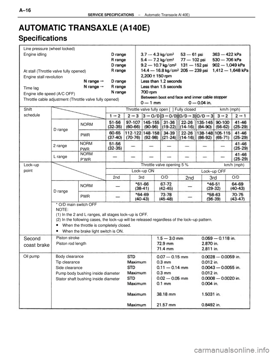
Line pressure (wheel locked)
Engine idling
At stall (Throttle valve fully opened)
Engine stall revolution
Time lag
Engine idle speed (A/C OFF)
Throttle cable adjustment (Throttle valve fully opened)
* O/D main switch OFF
NOTE:
(1) In the 2 and L ranges, all stages lock±up is OFF.
(2) In the following cases, the lock±up will be released regardless of the lock±up pattern.
wWhen the throttle is completely closed.
wWhen the brake light switch is ON.
Body clearance
Tip clearance
Side clearance
Pump body bushing inside diameter
Stator shaft bushing inside diameter
AUTOMATIC TRANSAXLE (A140E)
Specifications
Throttle valve fully open [ ] Fully closed
Piston stroke
Piston rod lengthThrottle valve opening 5 %
Second
coast brake
km/h (mph) Shift
schedule
Lock±up
point
Lock±up OFFkm/h (mph)
Lock±up ON NORM
P'WR NORM
PWR
Oil pumpD range
D range 2 range
L range
NORMNORM
O/D O/D
PWRPWR
2nd 3rd
2nd3rd
± SERVICE SPECIFICATIONSAutomatic Tiransaxle Al 40E)A±16
Page 2254 of 2389
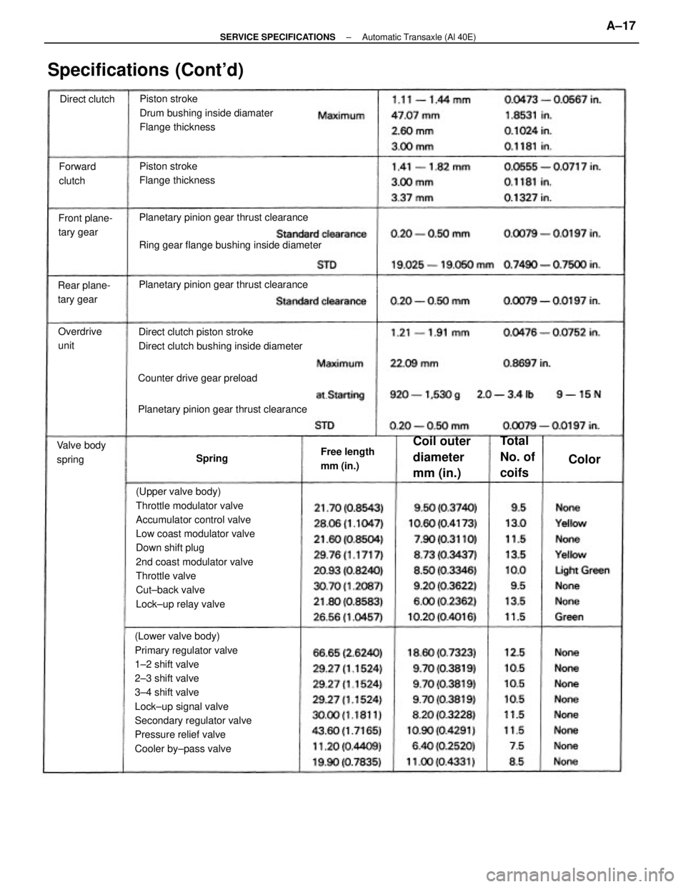
(Upper valve body)
Throttle modulator valve
Accumulator control valve
Low coast modulator valve
Down shift plug
2nd coast modulator valve
Throttle valve
Cut±back valve
Lock±up relay valve
(Lower valve body)
Primary regulator valve
1±2 shift valve
2±3 shift valve
3±4 shift valve
Lock±up signal valve
Secondary regulator valve
Pressure relief valve
Cooler by±pass valvePlanetary pinion gear thrust clearance
Ring gear flange bushing inside diameterPiston stroke
Drum bushing inside diamater
Flange thickness
Direct clutch piston stroke
Direct clutch bushing inside diameterPlanetary pinion gear thrust clearance
Planetary pinion gear thrust clearance
Specifications (Cont'd)
Piston stroke
Flange thickness
Counter drive gear preload
Coil outer
diameter
mm (in.)
Rear plane-
tary gearFront plane-
tary gear
Free length
mm (in.) Valve body
springOverdrive
unit
Total
No. of
coifs
Forward
clutchDirect clutch
Spring
Color
± SERVICE SPECIFICATIONSAutomatic Transaxle (Al 40E)A±17
Page 2258 of 2389
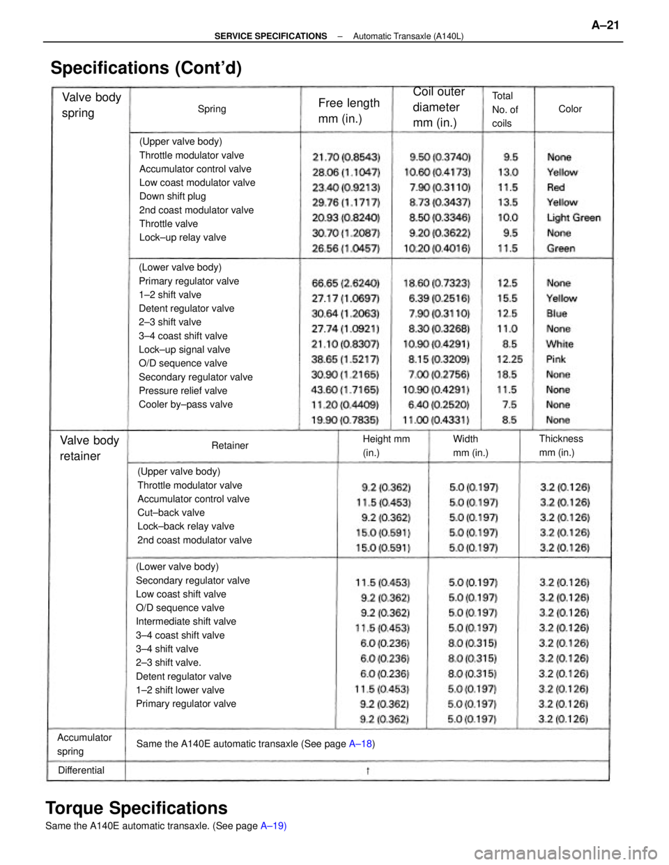
(Lower valve body)
Secondary regulator valve
Low coast shift valve
O/D sequence valve
Intermediate shift valve
3±4 coast shift valve
3±4 shift valve
2±3 shift valve.
Detent regulator valve
1±2 shift lower valve
Primary regulator valve(Lower valve body)
Primary regulator valve
1±2 shift valve
Detent regulator valve
2±3 shift valve
3±4 coast shift valve
Lock±up signal valve
O/D sequence valve
Secondary regulator valve
Pressure relief valve
Cooler by±pass valve(Upper valve body)
Throttle modulator valve
Accumulator control valve
Low coast modulator valve
Down shift plug
2nd coast modulator valve
Throttle valve
Lock±up relay valve
(Upper valve body)
Throttle modulator valve
Accumulator control valve
Cut±back valve
Lock±back relay valve
2nd coast modulator valve
Torque Specifications
Same the A140E automatic transaxle. (See page A±19) Same the A140E automatic transaxle (See page A±18)
Specifications (Cont'd)
Coil outer
diameter
mm (in.)
Accumulator
spring
Free length
mm (in.) Valve body
spring
Thickness
mm (in.)Valve body
retainer
Total
No. of
coils
Height mm
(in.)Width
mm (in.)
DifferentialColor
Retainer Spring
± SERVICE SPECIFICATIONSAutomatic Transaxle (A140L)A±21
Page 2260 of 2389
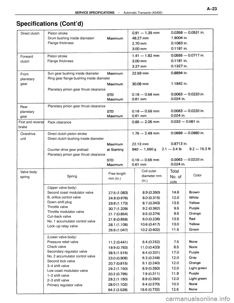
(Lower valve body)
Pressure relief valve
Check valve
Secondary regulator valve
No. 2 accumulator control valve
Second lock valve
3±4 shift valve
Low coast modulator valve
1±2 shift valve
2±3 shift valve
Primary regulator valve(Upper valve body)
Second coast modulator valve
B, orifice control valve
Down±shift plug
Throttle valve
Throttle modulator valve
Cut±back vaIve
No. 1 accumulator control valve
Lock±up relay valvePiston stroke
Drum bushing inside diamaterr
Flange thickness
Sun gear bushing inside diameter
Ring gear flange bushing inside diameter
Counter drive gear preload
Planetary pinion gear thrust clearanceDirect clutch piston stroke
Direct clutch bushing inside diameter Planetary pinion gear thrust clearancePlanetary pinion gear thrust clearance
Specifications (Cont'd)
Piston stroke
Flange thickness
Coil outer
diameter mm
(in.) Rear
planetary
gearFront
planetary
gear Forward
clutch
First and reverse
brake
Free length
mm (in.) Valve body
springOverdrive
unit
Total
No. of
coils Pack clearance Direct clutch
SpringColor
± SERVICE SPECIFICATIONSAutomatic Transaxle (A540E)A±23
Page 2276 of 2389
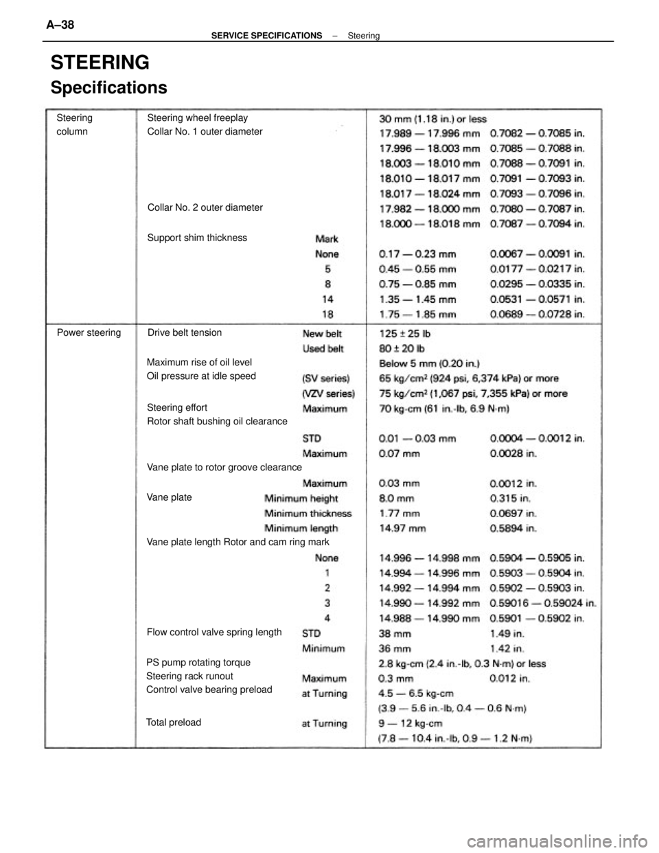
PS pump rotating torque
Steering rack runout
Control valve bearing preload
STEERING
Specifications
Steering effort
Rotor shaft bushing oil clearanceSteering wheel freeplay
Collar No. 1 outer diameter
Vane plate length Rotor and cam ring markMaximum rise of oil level
Oil pressure at idle speed
Vane plate to rotor groove clearance
Flow control valve spring lengthCollar No. 2 outer diameter
Support shim thickness
Drive belt tension Steering
column
Power steering
Total preloadVane plate
± SERVICE SPECIFICATIONSSteeringA±38
Page 2336 of 2389
SERVICE HINT
Troubles with the power steering system are usually
concerned with hard steering due to the fact that
there is no assist. In such cases, before attempting
to make repairs, it is necessary to determine wheth-
er the trouble lies with the pump or with the gear
housing. To do this, an on±vehicle inspection can be
made by using a pressure gauge.
ON±VEHICLE INSPECTION
Power steering is a hydraulic device and problems
are normally due to insufficient fluid pressure acting
on the piston. This could be caused by either the
pump not producing the specified fluid pressure or
the control valve in the gear housing not functioning
properly so that the proper fluid pressure can not be
obtained.
If the fault lies with the pump, the same symptoms
will generally occur whether the steering wheel is
turned fully to the right or left. On the other hand, if
the fault lies with the control valve, there will gener-
ally be difference between the amount of assist
when the steering wheel is turned to the left and
right, causing harder steering. However, if the piston
seal of the power cylinder is worn, there will be a
loss of fluid pressure whether the steering wheel is
turned to the right or left and the symptoms will be
the same for both.
Before performing an on±vehicle inspection, a
check must first be made to confirm that the power
steering system is completely free of any air. If there
is any air in the system, the volume of this air wilt
change when the fluid pressure raised, causing a
fluctuation in the fluid pressure so that the power
steering will not function properly. To determine if
there is any air in the system, check to see if there
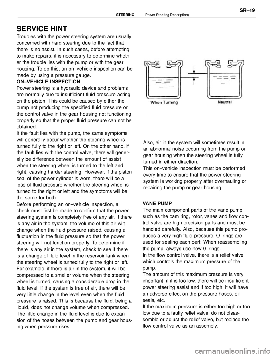
is a change of fluid level in the reservoir tank when
the steering wheel is turned fully to the right or left.
For example, if there is air in the system, it will be
compressed to a smaller volume when the steering
wheel is turned, causing a considerable drop in the
fluid level. If the system is free of air, there will be
very little change in the level even when the fluid
pressure is raised. This is because the fluid, being a
liquid, does not change volume when compressed.
The little change in the fluid level is due to expan-
sion of the hoses between the pump and gear hous-
ing when pressure rises.VANE PUMP
The main component parts of the vane pump,
such as the cam ring, rotor, vanes and flow con-
trol valve are high precision parts and must be
handled carefully. Also, because this pump pro-
duces a very high fluid pressure, O±rings are
used for sealing each part. When reassembling
the pump, always use new 0±rings.
In the flow control valve, there is a relief valve
which controls the maximum pressure of the
pump.
The amount of this maximum pressure is very
important; if it is too low, there will be insufficient
power steering assist and if too high, it will have
an adverse effect on the pressure hoses, oil
seals, etc.
If the maximum pressure is either too high or too
low due to a faulty relief valve, do not disas-
semble or adjust the relief valve, but replace the
flow control valve as an assembly.Also, air in the system will sometimes result in
an abnormal noise occurring from the pump or
gear housing when the steering wheel is fully
turned in either direction.
This on±vehicle inspection must be performed
every time to ensure that the power steering
system is working properly after overhauling or
repairing the pump or gear housing.
± STEERINGPower Steering Description)SR±19
Page 2337 of 2389
The oil seals on both sides of the power cylinder
are for the prevention of leakage of the high
pressure fluid which acts on the piston. Always
use new oil seals when reassembling and be
very careful not to scratch or damage them.
Because of the high pressure, even the slightest
scratch will cause fluid leakage, resulting in an
inoperative power steering system.
Also, be very careful not to scratch the sliding
portion of the rack which makes contact with the
oil seals. When removing the rack ends from the
rack, it is very easy to cause a burr when hold-
ing the tip of the rack with a wrench. Therefore,
before assembling the rack, first check the tip for
burrs and remove any with an oil stone.
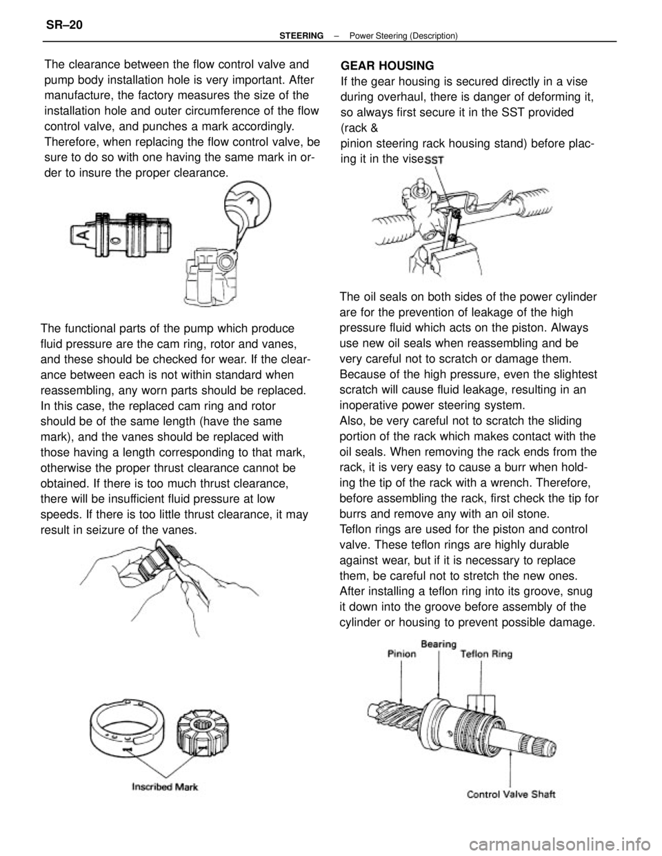
Teflon rings are used for the piston and control
valve. These teflon rings are highly durable
against wear, but if it is necessary to replace
them, be careful not to stretch the new ones.
After installing a teflon ring into its groove, snug
it down into the groove before assembly of the
cylinder or housing to prevent possible damage. The functional parts of the pump which produce
fluid pressure are the cam ring, rotor and vanes,
and these should be checked for wear. If the clear-
ance between each is not within standard when
reassembling, any worn parts should be replaced.
In this case, the replaced cam ring and rotor
should be of the same length (have the same
mark), and the vanes should be replaced with
those having a length corresponding to that mark,
otherwise the proper thrust clearance cannot be
obtained. If there is too much thrust clearance,
there will be insufficient fluid pressure at low
speeds. If there is too little thrust clearance, it may
result in seizure of the vanes.The clearance between the flow control valve and
pump body installation hole is very important. After
manufacture, the factory measures the size of the
installation hole and outer circumference of the flow
control valve, and punches a mark accordingly.
Therefore, when replacing the flow control valve, be
sure to do so with one having the same mark in or-
der to insure the proper clearance.GEAR HOUSING
If the gear housing is secured directly in a vise
during overhaul, there is danger of deforming it,
so always first secure it in the SST provided
(rack &
pinion steering rack housing stand) before plac-
ing it in the vise.
± STEERINGPower Steering (Description)SR±20
Page 2351 of 2389
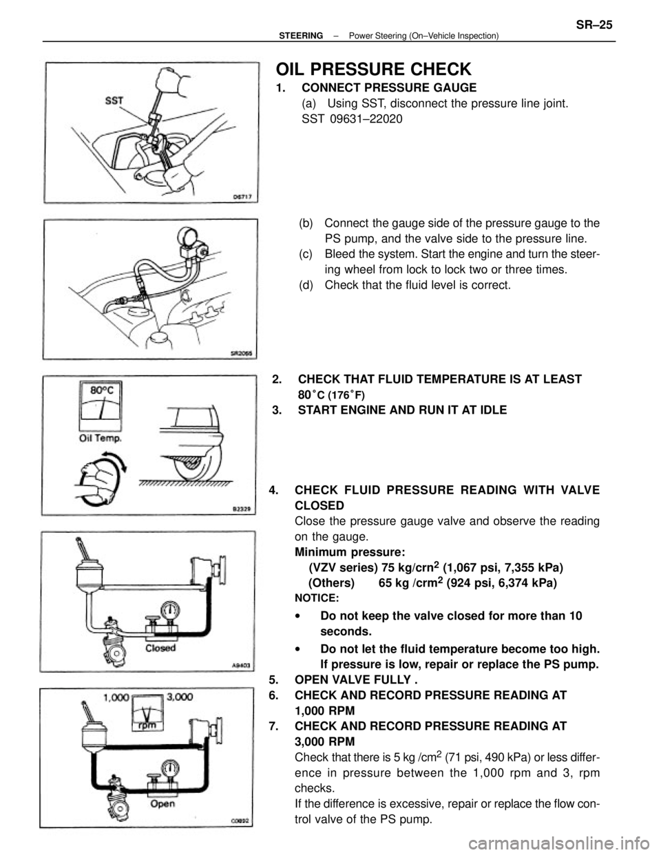
4. CHECK FLUID PRESSURE READING WITH VALVE
CLOSED
Close the pressure gauge valve and observe the reading
on the gauge.
Minimum pressure:
(VZV series) 75 kg/crn
2 (1,067 psi, 7,355 kPa)
(Others) 65 kg /crm
2 (924 psi, 6,374 kPa)
NOTICE:
wDo not keep the valve closed for more than 10
seconds.
wDo not let the fluid temperature become too high.
If pressure is low, repair or replace the PS pump.
5. OPEN VALVE FULLY .
6. CHECK AND RECORD PRESSURE READING AT
1,000 RPM
7. CHECK AND RECORD PRESSURE READING AT
3,000 RPM
Check that there is 5 kg /cm
2 (71 psi, 490 kPa) or less differ-
ence in pressure between the 1,000 rpm and 3, rpm
checks.
If the difference is excessive, repair or replace the flow con-
trol valve of the PS pump.(b) Connect the gauge side of the pressure gauge to the
PS pump, and the valve side to the pressure line.
(c) Bleed the system. Start the engine and turn the steer-
ing wheel from lock to lock two or three times.
(d) Check that the fluid level is correct.
OIL PRESSURE CHECK
1. CONNECT PRESSURE GAUGE
(a) Using SST, disconnect the pressure line joint.
SST 09631±22020
2. CHECK THAT FLUID TEMPERATURE IS AT LEAST
80
°C (176°F)
3. START ENGINE AND RUN IT AT IDLE
± STEERINGPower Steering (On±Vehicle Inspection)SR±25