Page 264 of 2389

3. Hydraulic Control System
CONSTRUCTION
The hydraulic control is composed of an oil pump, rotated by the engine, which supplies hydraulic pres-
sure; a valve body which controls the hydraulic pressure and the opening and closing of the fluid pas-
saged; and a governor valve which supplies hydraulic pressure in accordance with vehicle speed.
OPERATION
Hydraulic pressure supplied by the oil pump is controlled± by the regulator valve; the resulting oil pres-
sure controlled by the regulator valve is called the line pressure.
Line pressure produces the hydraulic pressure for throttle pressure and governor pressure. Also, line
pressure produces hydraulic pressure for the operation of each brake and clutch in the planetary gear
unit.
The throttle valve acts to produce hydraulic pressure, called the throttle pressure, which responds to ac-
celerator pedal modulation. Throttle pressure increases as the accelerator pedal is depressed.
The governor valve produces hydraulic pressure, called the governor pressure, in response to vehicle
speed. Governor pressure increases as vehicle speed increases.
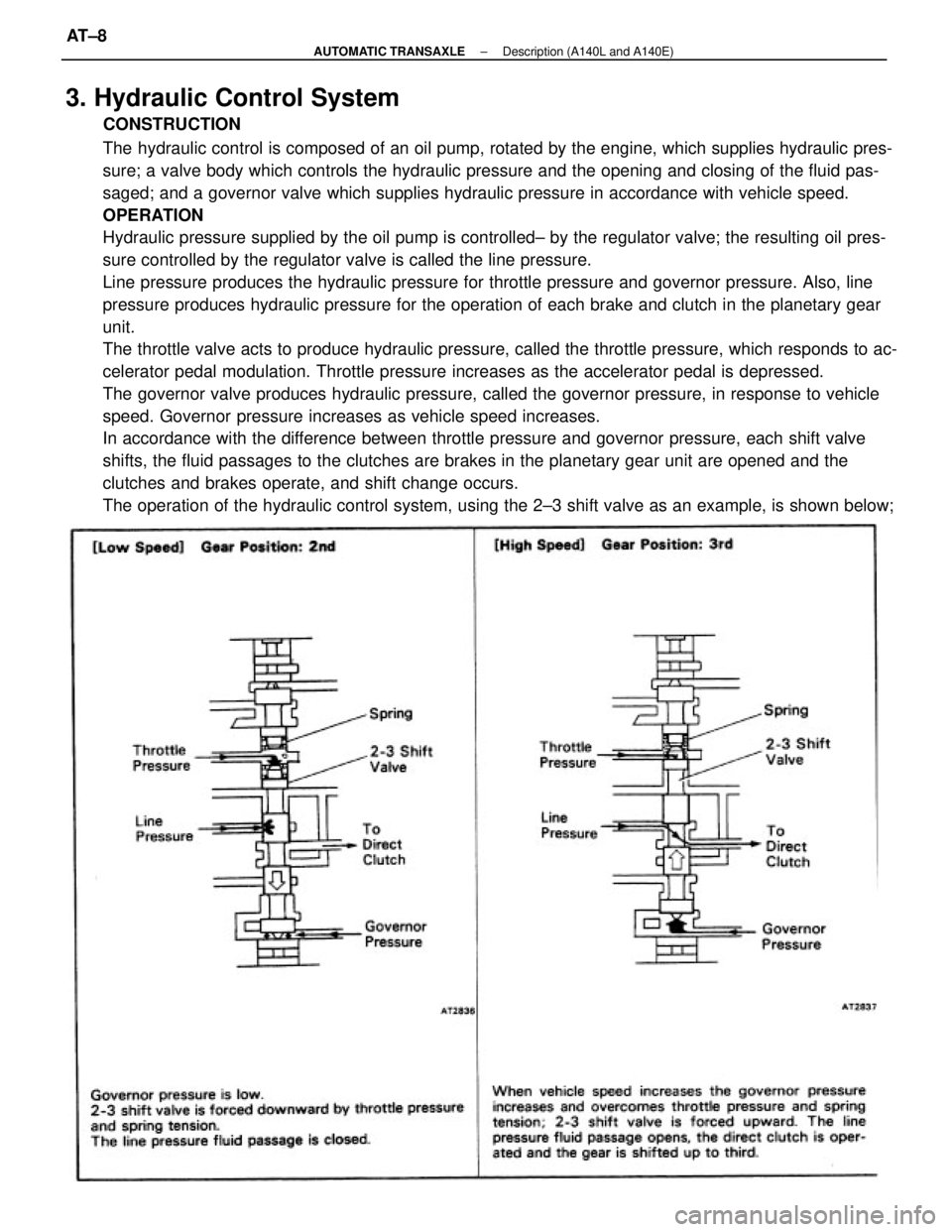
In accordance with the difference between throttle pressure and governor pressure, each shift valve
shifts, the fluid passages to the clutches are brakes in the planetary gear unit are opened and the
clutches and brakes operate, and shift change occurs.
The operation of the hydraulic control system, using the 2±3 shift valve as an example, is shown below;
± AUTOMATIC TRANSAXLEDescription (A140L and A140E)AT±8
Page 296 of 2389
EVALUATION
(a) If the measured values at all ranges are higher than specified:
wThrottle cable out of adjustment
w4 Throttle valve defective
Regulator valve defective
(b) If the measured values at all ranges are lower than specified:
wThrottle cable out of adjustment
wThrottle valve defective
wRegulator valve defective
wOil pump defective
wO/D direct clutch defective
(c) If pressure is low in the D range only:
wD range circuit fluid leakage
wForward clutch defective
(d) If pressure is low in the R range only:
wR range circuit fluid leakage
wDirect clutch defective
wFirst and reverse brake defective
± AUTOMATIC TRANSAXLETroubleshooting (Mechanical System Tests) (A140L and
A140E)AT±41
Page 347 of 2389
2. INSPECT DISCS, PLATES AND FLANGE
Check if the sliding surfaces of the discs, plates are
flange are worn or burnt. If necessary, replace them.
HINT:
wIf the lining of the disc is exfoliated or discolored, o
even a part of the printed numbers are defaced, re-
place all discs.
wBefore assembling new discs, soak them in ATF for
at least two hours.
INSPECTION OF FORWARD CLUTCH
1. INSPECT CLUTCH PISTON
(a) Check that the check ball is free by shaking the piston.
(b) Check that the valve does not leak by applying low pressure
compressed air. 6. IF NECESSARY, REMOVE OIL SEAL RINGS
Remove the two oil seal rings from the shaft.(b) Remove the two O±rings from the piston.
± AUTOMATIC TRANSAXLEComponent Parts (Forward Clutch) (A140L and A140E)AT±92
Page 461 of 2389
If the measured pressure are not up to specified values, recheck the throttle cable adjustment and
perform a retest.
EVALUATION
(a) If the measured values at all ranges are higher than specified:
wThrottle cable out of adjustment
wThrottle valve defective
wRegulator valve defective
(b) If the measured values at all ranges are lower than specified:
wThrottle cable out of adjustment
wThrottle valve defective
wRegulator valve defective
wOil pump defective
wO/D direct clutch defective
(e) If pressure is low in the D range only:
wD range circuit fluid leakage
wForward clutch defective
(d) If pressure is low in the R range only:
wR range circuit fluid leakage
wDirect clutch defective
wFirst and reverse brake defective
kg/cm2 (psi, kPa)
Line pressure
(A540H)
R rangeD
rang
e Id-
lin
g
IdlingS
t
al
l
Stall
± AUTOMATIC TRANSAXLETroubleshooting (Mechanical System Tests) (A540E and
A540H)AT±225
Page 532 of 2389

ASSEMBLY OF FORWARD CLUTCH
1. (A540E, A540H)
INSTALL OIL SEAL RINGS
Install the three oil seal rings (A540E) or two oil seal rings
(A540H) to the shaft.
NOTICE: Do not spread the ring ends more than necessary.
HINT: After installing the oil seal rings, check that they move
smoothly.
2. INSTALL CLUTCH PISTON TO CLUTCH DRUM
(a) Install the two new O±rings, to the piston. 2. INSPECT DISCS, PLATES AND FLANGE
Check if the sliding surfaces of the discs, plates and
flange are worn or burnt. If necessary, replace them.
HINT:
wIf the lining of the disc is exfoliated or discolored, or
even a part of the printed numbers are defaced, re-
place all discs.
wBefore assembling new discs, soak them in ATF for
at least fifteen minutes.
INSPECTION OF FORWARD CLUTCH
1. INSPECT CLUTCH PISTON
(a) Check that the check ball is free by shaking the piston.
(b) Check that the valve does not leak by applying low
pressure compressed air. (A540H)
Remove the two oil seal rings from the
shaft.
± AUTOMATIC TRANSAXLEComponent Parts (Forward Clutch) (A±540E and A540H)AT±277
Page 578 of 2389
HINT: During reassembly please refer to the spring specifications above to help discriminate the
different springs.
SECTIONAL VIEW OF VALVE BODY SPECIFICATIONS OF VALVE BODY SPRINGS
No. 2 accumulator control valveCoil outer diameter
mm (in.) Free length mm (in.)
Secondary regulator valve
Low coast modulator valve
Primary regulator valve Pressure relief valve
Second lock valveTotal No. of coils
1±2 shift valve 3±4 shift valve
2±3 shift valveLight Green
Light Green Check valve
Orange Spring
Purple PurpleColor
None None
None None Gray
± AUTOMATIC TRANSAXLEComponent Parts (Valve Body A540E and A540H)AT±316
Page 690 of 2389

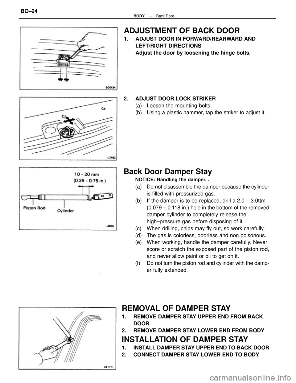
Back Door Damper Stay
NOTICE: Handling the damper. .
(a) Do not disassemble the damper because the cylinder
is filled with pressurized gas.
(b) If the damper is to be replaced, drill a 2.0 ± 3.0ttm
(0.079 ± 0.118 in.) hole in the bottom of the removed
damper cylinder to completely release the
high±pressure gas before disposing of it.
(c) When drilling, chips may fly out, so work carefully.
(d) The gas is colorless, odorless and non poisonous.
(e) When working, handle the damper carefully. Never
score or scratch the exposed part of the piston rod,
and never allow paint or oil to get on it.
(f) Do not turn the piston rod and cylinder with the damp-
er fully extended.
REMOVAL OF DAMPER STAY
1. REMOVE DAMPER STAY UPPER END FROM BACK
DOOR
2. REMOVE DAMPER STAY LOWER END FROM BODY
INSTALLATION OF DAMPER STAY
1. INSTALL DAMPER STAY UPPER END TO BACK DOOR
2. CONNECT DAMPER STAY LOWER END TO BODY
ADJUSTMENT OF BACK DOOR
1. ADJUST DOOR IN FORWARD/REARWARD AND
LEFT/RIGHT DIRECTIONS
Adjust the door by loosening the hinge bolts.
2. ADJUST DOOR LOCK STRIKER
(a) Loosen the mounting bolts.
(b) Using a plastic hammer, tap the striker to adjust it.
± BODYBack DoorBO±24
Page 777 of 2389

Replace fuse and check for short
Replace bulb
Check switch
Check switch
Check switch
Check relay
Repair a s necessary ºDOMEº fuse blown
Bulb burned out
Door courtesy switch faulty
Unlock warning switch faulty
Buckle switch faulty
Seat belt warning relay faulty
Wiring or ground faultyºGAUGEº fuse blown
Bulb burned out
Brake fluid level warning switch faulty
Parking brake switch faulty
Wiring or ground faultyReplace fuse and check for short
Replace bulb
Check switch
Check switch
Repair as necessary ºGAUGEº fuse blown
Water temperature gauge faulty
Water temperature sender gauge faulty
Wiring or ground faulty
ºGAUGEº fuse blown
Buibburned out
oil pressure warning switch faulty
Wiring or ground faultyºGAUGEº fuse blown
Bulb burned out
Fuel level warning switch faulty
Wiring or ground faulty
Replace fuse and check for short
Replace bulb
Check switch
±Repair as necessaryReplace fuse and check for short
Replace bulb
Check switch
Repair as necessary
Replace fuse and check for short
Replace bulb
Check switch
Repair as necessaryReplace fuse and check for short
Check gauge
Check sender gauge
Repair as necessaryReplace fuse .and check for short
Check gauge
Check sender gauge
Repair as necessary
COMBINATION METER
Troubleshooting
ºGAUGEº fuse blown
Bulb burned out
Door courtesy switch faulty
Wiring or ground faultyReplace fuse and check for short
Check tachometer
Repair as necessary
ºGAUGEº fuse blown
Fuel gauge faulty
Sender gauge faulty
Wiring or ground faultyºGAUGEº fuse blown
Tachometer faulty
Wiring faulty
Low oil pressure warning
light does not lightWater temperature
gauge does not
operate
Seat belt warning
does not operate
(Canada)Tachometer does not
operate
Brake warning light does
not lightFuel gauge does not
operate
Open door warning light
does not lightFuel level warning light
does not light
BE±40
BE±13
BE±41
BE±41BE±3
BE±38
BE±39BE±3
BE±36
BE±37 Possible cause
BE±3
BE±36
BE±40
BE±40 Problem
Remedy
BE±40BE±39BE±37Page
BE±3BE±3
BE±3
BE±3
BE±3
± BODY ELECTRICAL SYSTEMCombination MeterBE±31