1986 TOYOTA CAMRY V20 low oil pressure
[x] Cancel search: low oil pressurePage 1226 of 2389
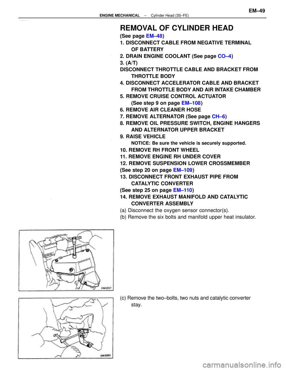
REMOVAL OF CYLINDER HEAD
(See page EM±48)
1. DISCONNECT CABLE FROM NEGATIVE TERMINAL
OF BATTERY
2. DRAIN ENGINE COOLANT (See page CO±4)
3. (A/T)
DISCONNECT THROTTLE CABLE AND BRACKET FROM
THROTTLE BODY
4. DISCONNECT ACCELERATOR CABLE AND BRACKET
FROM THROTTLE BODY AND AIR INTAKE CHAMBER
5. REMOVE CRUISE CONTROL ACTUATOR
(See step 9 on page EM±108)
6. REMOVE AIR CLEANER HOSE
7. REMOVE ALTERNATOR (See page CH±6)
8. REMOVE OIL PRESSURE SWITCH, ENGINE HANGERS
AND ALTERNATOR UPPER BRACKET
9. RAISE VEHICLE
NOTICE: Be sure the vehicle is securely supported.
10. REMOVE RH FRONT WHEEL
11. REMOVE ENGINE RH UNDER COVER
12. REMOVE SUSPENSION LOWER CROSSMEMBER
(See step 20 on page EM±109)
13. DISCONNECT FRONT EXHAUST PIPE FROM
CATALYTIC CONVERTER
(See step 25 on page EM±110)
14. REMOVE EXHAUST MANIFOLD AND CATALYTIC
CONVERTER ASSEMBLY
(a) Disconnect the oxygen sensor connector(s).
(b) Remove the six bolts and manifold upper heat insulator.
(c) Remove the two±bolts, two nuts and catalytic converter
stay.
± ENGINE MECHANICALCylinder Head (3S±FE)EM±49
Page 1234 of 2389
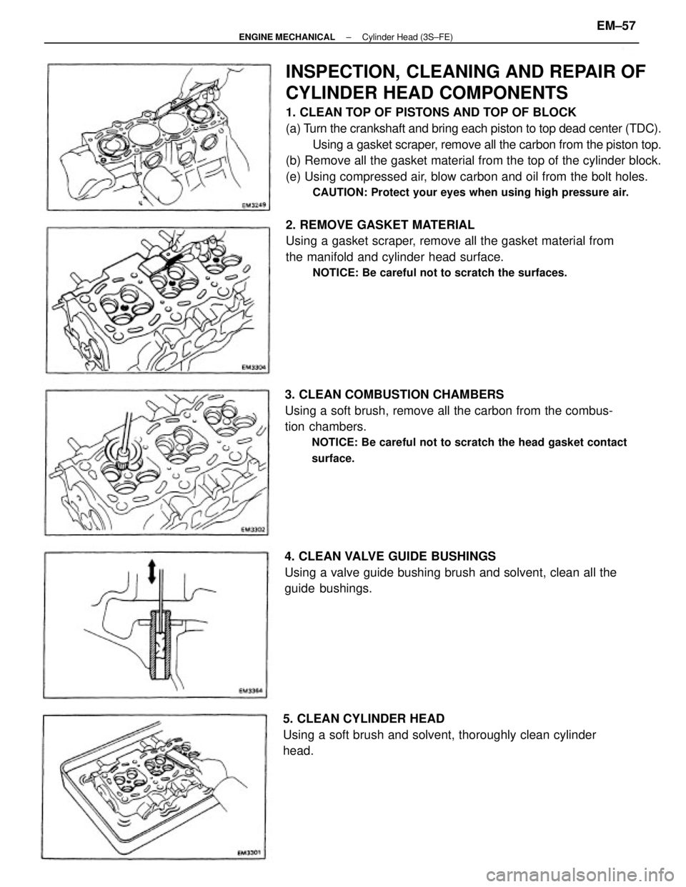
INSPECTION, CLEANING AND REPAIR OF
CYLINDER HEAD COMPONENTS
1. CLEAN TOP OF PISTONS AND TOP OF BLOCK
(a) Turn the crankshaft and bring each piston to top dead center (TDC).
Using a gasket scraper, remove all the carbon from the piston top.
(b) Remove all the gasket material from the top of the cylinder block.
(e) Using compressed air, blow carbon and oil from the bolt holes.
CAUTION: Protect your eyes when using high pressure air.
2. REMOVE GASKET MATERIAL
Using a gasket scraper, remove all the gasket material from
the manifold and cylinder head surface.
NOTICE: Be careful not to scratch the surfaces.
3. CLEAN COMBUSTION CHAMBERS
Using a soft brush, remove all the carbon from the combus-
tion chambers.
NOTICE: Be careful not to scratch the head gasket contact
surface.
4. CLEAN VALVE GUIDE BUSHINGS
Using a valve guide bushing brush and solvent, clean all the
guide bushings.
5. CLEAN CYLINDER HEAD
Using a soft brush and solvent, thoroughly clean cylinder
head.
± ENGINE MECHANICALCylinder Head (3S±FE)EM±57
Page 1262 of 2389
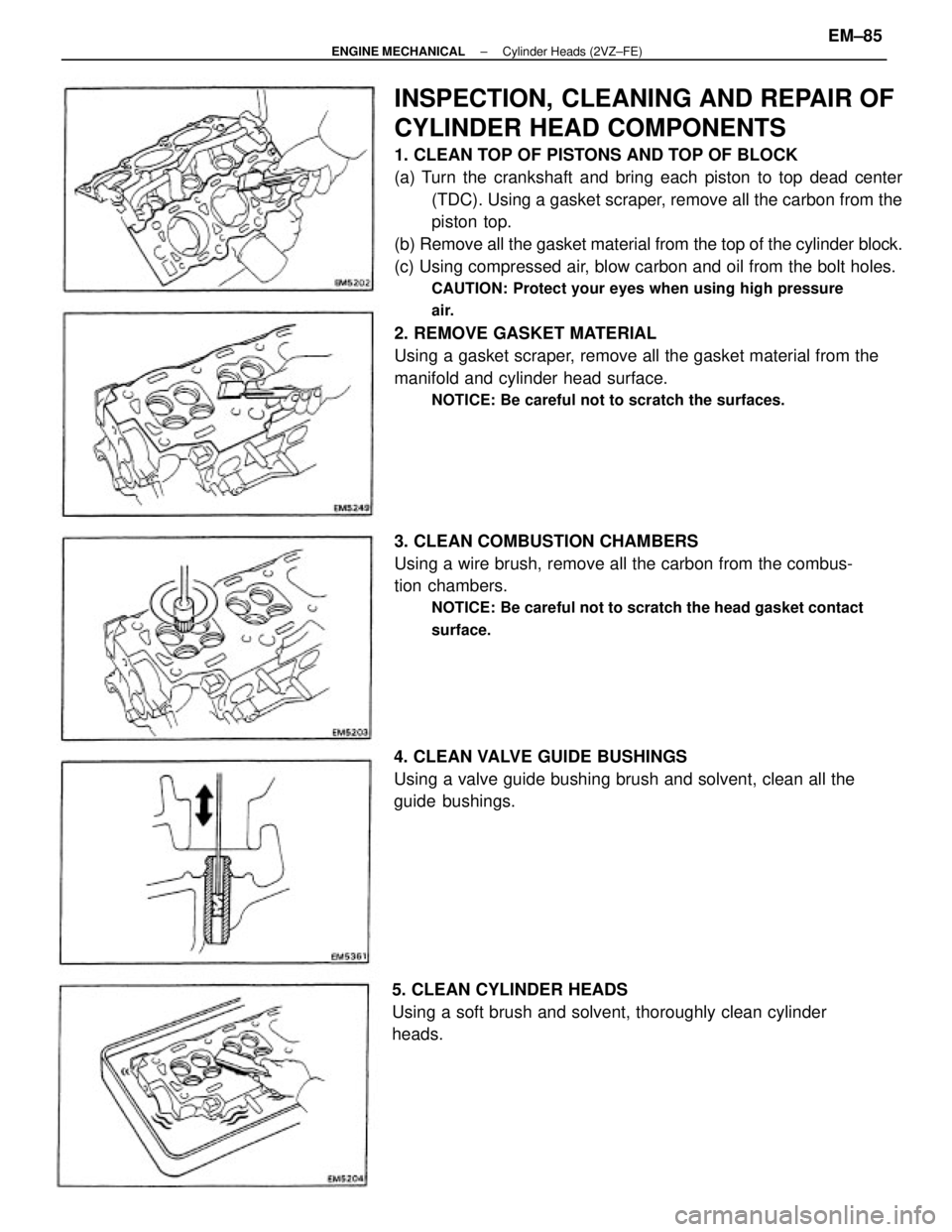
INSPECTION, CLEANING AND REPAIR OF
CYLINDER HEAD COMPONENTS
1. CLEAN TOP OF PISTONS AND TOP OF BLOCK
(a) Turn the crankshaft and bring each piston to top dead center
(TDC). Using a gasket scraper, remove all the carbon from the
piston top.
(b) Remove all the gasket material from the top of the cylinder block.
(c) Using compressed air, blow carbon and oil from the bolt holes.
CAUTION: Protect your eyes when using high pressure
air.
2. REMOVE GASKET MATERIAL
Using a gasket scraper, remove all the gasket material from the
manifold and cylinder head surface.
NOTICE: Be careful not to scratch the surfaces.
3. CLEAN COMBUSTION CHAMBERS
Using a wire brush, remove all the carbon from the combus-
tion chambers.
NOTICE: Be careful not to scratch the head gasket contact
surface.
4. CLEAN VALVE GUIDE BUSHINGS
Using a valve guide bushing brush and solvent, clean all the
guide bushings.
5. CLEAN CYLINDER HEADS
Using a soft brush and solvent, thoroughly clean cylinder
heads.
± ENGINE MECHANICALCylinder Heads (2VZ±FE)EM±85
Page 1844 of 2389
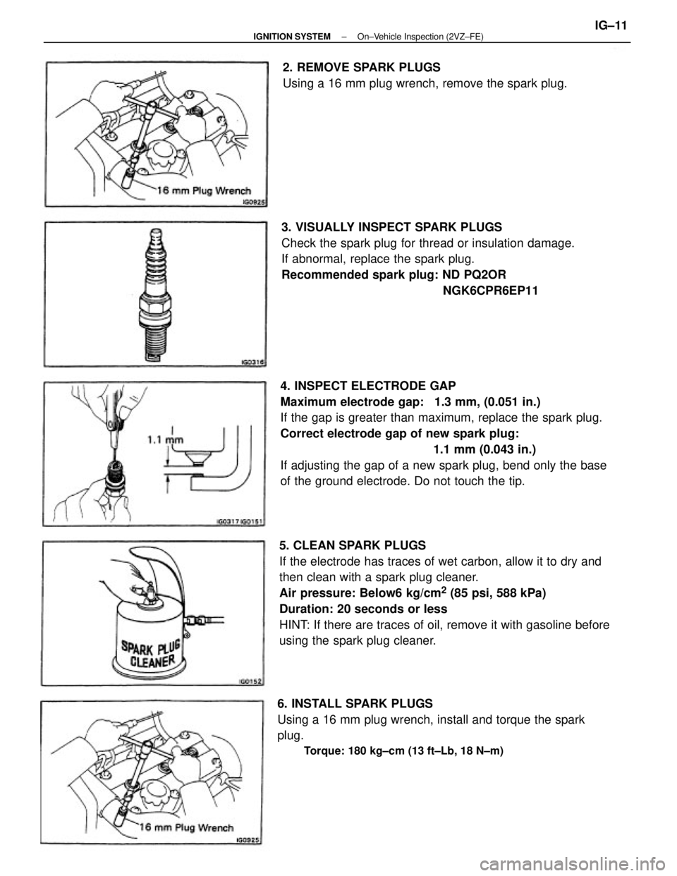
4. INSPECT ELECTRODE GAP
Maximum electrode gap: 1.3 mm, (0.051 in.)
If the gap is greater than maximum, replace the spark plug.
Correct electrode gap of new spark plug:
1.1 mm (0.043 in.)
If adjusting the gap of a new spark plug, bend only the base
of the ground electrode. Do not touch the tip.
5. CLEAN SPARK PLUGS
If the electrode has traces of wet carbon, allow it to dry and
then clean with a spark plug cleaner.
Air pressure: Below6 kg/cm
2 (85 psi, 588 kPa)
Duration: 20 seconds or less
HINT: If there are traces of oil, remove it with gasoline before
using the spark plug cleaner.3. VISUALLY INSPECT SPARK PLUGS
Check the spark plug for thread or insulation damage.
If abnormal, replace the spark plug.
Recommended spark plug: ND PQ2OR
NGK6CPR6EP11
6. INSTALL SPARK PLUGS
Using a 16 mm plug wrench, install and torque the spark
plug.
Torque: 180 kg±cm (13 ft±Lb, 18 N±m)
2. REMOVE SPARK PLUGS
Using a 16 mm plug wrench, remove the spark plug.
± IGNITION SYSTEMOn±Vehicle Inspection (2VZ±FE)IG±11
Page 1889 of 2389
A pressure feeding lubrication system has been adopted to supply oil to the moving parts of this engine.
The lubrication system consists of an oil pan, oil pump, oil filter and other external parts which supply oil
to the moving parts in the engine block The oil circuit is shown in the illustration at the top of the pre-
vious page. Oil from the oil pan is pumped up by the oil pump. After it passes through the oil filter, it is
fed through the various oil holes in the crankshaft and cylinder block. After passing through the cylinder
block and performing its lubricating function, the oil is returned by gravity to the oil pan. A dipstick on the
center left side of the cylinder block is provided to check the oil level.
OIL PUMP
The oil pump pumps up oil from the oil pan and sends it under pressure to the various parts of the en-
gine.
An oil strainer is mounted in front of the inlet to the oil pump. The oil pump itself is a trochoid±type
pump, inside of which is a drive rotor and a driven rotor. 'When the drive rotor rotates, the driven rotor
rotates in the same direction, and since the axis of the driven rotor shaft is different from the center of
the driven rotor, the space between the two rotors is changed as they rotate. Oil is drawn in when the
space is wide and is discharged when the space in narrow.
OIL PRESSURE REGULATOR (RELIEF VALVE)
At high engine speeds, the engine oil supplied by the oil pump exceeds the capacity of the engine to
utilize it.
For that reason, the oil pressure regulator works to prevent an oversupply of oil. During normal oil sup-
ply, a coil spring and valve keep the by±pass closed, but when too much oil is being fed, the pressure
become extremely high, overpowering the force of the spring and opening the valves. This allows the
excess oil to flow through the valve and return to the oil pan.
OIL FILTER
The oil filter is a full flow type filter with a built±in paper filter element, Particles of metal from wear, air-
born dirt, carbon and other impurities can get in the oil during use and could cause accelerated wear or
seizing if allowed to circulate through the engine. The oil filter, integrated into the oil line, removes these
impurities as the oil passes through it. The filter is mounted outside the engine to simplify replacement of
the filter element.
A relief valve is also included ahead of the filter element to relieve the high oil pressure in case the filter
element becomes clogged with impurities. The relief valve opens when the oil pressure overpowers the
force of the spring. Oil passing through the relief valve by±passes the oil filter and flows directly into the
main oil hole in the engine.
± LUBRICATION SYSTEMDescriptionLU±4
Page 1890 of 2389
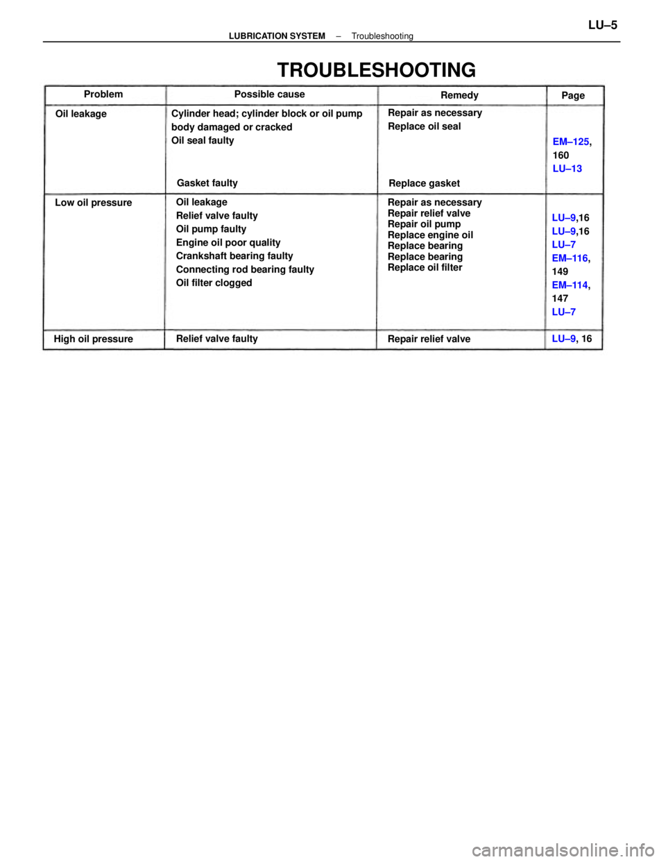
Oil leakage
Relief valve faulty
Oil pump faulty
Engine oil poor quality
Crankshaft bearing faulty
Connecting rod bearing faulty
Oil filter cloggedRepair as necessary
Repair relief valve
Repair oil pump
Replace engine oil
Replace bearing
Replace bearing
Replace oil filter Cylinder head; cylinder block or oil pump
body damaged or cracked
Oil seal faulty
LU±9,16
LU±9,16
LU±7
EM±116,
149
EM±114,
147
LU±7
TROUBLESHOOTING
Repair as necessary
Replace oil seal
EM±125,
160
LU±13
Relief valve faulty
Repair relief valve High oil pressureLow oil pressureReplace gasket Possible cause
Gasket faulty Oil leakageRemedy
LU±9, 16 Problem
Page
± LUBRICATION SYSTEMTroubleshootingLU±5
Page 1891 of 2389
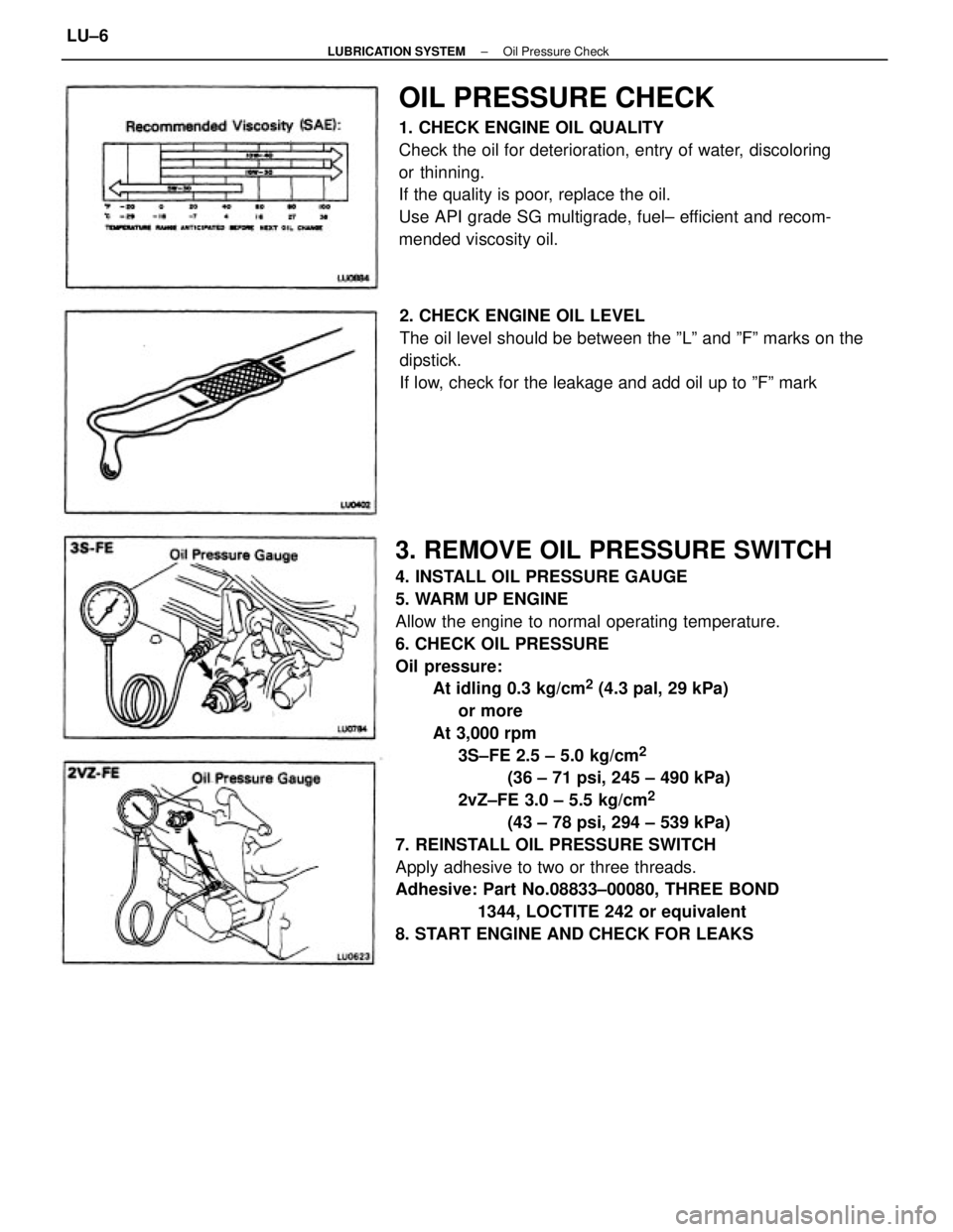
3. REMOVE OIL PRESSURE SWITCH
4. INSTALL OIL PRESSURE GAUGE
5. WARM UP ENGINE
Allow the engine to normal operating temperature.
6. CHECK OIL PRESSURE
Oil pressure:
At idling 0.3 kg/cm
2 (4.3 pal, 29 kPa)
or more
At 3,000 rpm
3S±FE 2.5 ± 5.0 kg/cm
2
(36 ± 71 psi, 245 ± 490 kPa)
2vZ±FE 3.0 ± 5.5 kg/cm
2
(43 ± 78 psi, 294 ± 539 kPa)
7. REINSTALL OIL PRESSURE SWITCH
Apply adhesive to two or three threads.
Adhesive: Part No.08833±00080, THREE BOND
1344, LOCTITE 242 or equivalent
8. START ENGINE AND CHECK FOR LEAKS
OIL PRESSURE CHECK
1. CHECK ENGINE OIL QUALITY
Check the oil for deterioration, entry of water, discoloring
or thinning.
If the quality is poor, replace the oil.
Use API grade SG multigrade, fuel± efficient and recom-
mended viscosity oil.
2. CHECK ENGINE OIL LEVEL
The oil level should be between the ºLº and ºFº marks on the
dipstick.
If low, check for the leakage and add oil up to ºFº mark
± LUBRICATION SYSTEMOil Pressure CheckLU±6
Page 1914 of 2389
GENERAL MAINTENANCE
These are the maintenance and inspection items
which are considered to be the owner's responsibility,
They can be performed by the owner or he
can have then done at a service shop. These items
include those which should be checked on a daily ba-
sis, those which, in most cases, do not require
(special) tools and those which are considered to be
reasonable for the owner to perform.
Items and procedures for general maintenance are as
follows:
OUTSIDE VEHICLE
1. TIRES
(a) Check the pressure with a gauge. Adjust
if necessary.
(b) Check for cuts, damage or excessive wear.
2. WHEEL NUTS
When checking the tires, check the nuts for looseness
or for missing nuts. If necessary,
tighten them.
3. TIRE ROTATION
It is recommended that tires be rotated every
7,500 miles (12,000 km).
4. WINDSHIELD WIPER BLADES
Check for wear or cracks whenever they do not wipe
clean. Replace if necessary.
5. FLUID LEAKS
(a) Check underneath for leaking fuel, oil, water or
other fluid.
(b) If you smell gasoline fumes or notice any leak,
have the cause found and corrected.
6. DOORS AND ENGINE HOOD
(a) Check that all doors including the trunk lid and
back door operate smoothly, and that all
latches lock securely.
(b) Check that the engine hood secondary latch se-
cures the hood from opening when the prima-
ry latch is released.
INSIDE VEHICLE
7. LIGHTS
(a) Check that the headlights, stop lights, taillights,
turn signal lights, and other
lights are all working.
(b) Check the headlight aiming.8. WARNING LIGHTS AND BUZZERS
Check that all warning lights and buzzers func-
tion properly.
9. HORN
Check that it is working.
10. WINDSHIELD GLASS
Check for scratches, pits or abrasions.
11. WINDSHIELD WIPER AND WASHER
(a) Check operation of the wipers and washer.
(b) Check that the wipers do not streak.
12. WINDSHIELD DEFROSTER
Check that air comes out from the defroster out-
let when operating the heater or air conditioner
at defroster mode.
13. REAR VIEW MIRROR
Check that it is mounted securely.
14. SUN VISORS
Check that they move freely and are mounted
securely.
15. STEERING WHEEL
Check that it has the specified freeplay. Be alert
for changes in steering condition, such as hard
steering, excessive freeplay or strange noise.
16. SEATS
(a) Check that all front seat controls such as
seat adjusters, seatback recliner, etc.
operate smoothly.
(b) Check that a11 latches lock securely in
any position.
(c) Check that the locks hold securely in any
latched position.
(d) Check that the head restraints move up
and down smoothly and that the locks
hold securely in any latched position.
(e) For folding±down rear seat backs, check
that the latches lock securely.
17. SEAT BELTS
(a) Check that the seat belt system such as
buckles, retractors and anchors operate
properly and smoothly.
(b) Check that the belt webbing is not cut,
frayed, worn or damaged.
± MAINTENANCEGeneral MaintenanceMA±16