Page 1406 of 2389

1. INSTALL FRONT DRIVE SHAFT
(a) Coat MP grease to the oil seal lip.
(b) Using a brass bar and a hammer, tap in the drive shaft
until it makes conta")
INSTILLATION OF FRONT DRIVE SHAFT
(See page FA±41)
1. INSTALL FRONT DRIVE SHAFT
(a) Coat MP grease to the oil seal lip.
(b) Using a brass bar and a hammer, tap in the drive shaft
until it makes contact with the pinion shaft.
NOTICE: Be careful not to damage the boots.
HINT:
wBefore installing the drive shaft, set the snap ring opening
side facing downward.
wWhether or not the drive shaft is making contact with the
pinion shaft can be known by the sound or feeling when driv-
ing it in.
2. CHECK INSTALLATION OF FRONT DRIVE SHAFT
(a) Check that there is 2 3 mm (0.08 0.12 in.) of play in axial
direction.
(b) Check that the drive shaft will not come out by trying to
pull it completely out by hand.
HINT: When checking pull the inboard joint so as not to
damage the boot.(c) Install the outboard joint side of the drive shaft to
the axle hub.
NOTICE: Be careful not to damage the boot.
3. CONNECT STEERING KNUCKLE TO LOWER ARM
Torque: 1,15O kg±cm (83 ft±Ib, 113 N±m)
± FRONT AXLE AND SUSPENSIONFront Drive Shaft (4WD)FA±49
Page 1409 of 2389
REMOVAL OF FRONT SHOCK ABSORBER
ASSEMBLY
1. DISCONNECT BRAKE HOSE
(a) Remove union bolt, and disconnect the brake hose from
the disc brake caliper.
(b) Drain the brake fluid into a container.
3. REMOVE SHOCK ABSORBER FROM BODY
(a) Remove the three bolts holding the top of the suspen-
sion support.
(b) Remove the shock absorber from the body.
NOTICE: Cover the drive shaft boot with cloth to avoid
damaging it.
2. DISCONNECT STEERING KNUCKLE FROM SHOCK
ABSORBER
Remove the bolts and nuts, and disconnect the steer-
ing knuckle from the shock absorber.
4. CLAMP SHOCK ABSORBER IN VISE
Install a bolt and two nuts to the bracket at the lower portion of
the shock absorber shell and secure it in a vise. (c) Remove the clip from the brake hose bracket.
(d) Pull off the brake hose from the brake hose bracket.
± FRONT AXLE AND SUSPENSIONFront Shock AbsorberFA±52
Page 1411 of 2389

1. INSTALL BUMPER, COIL SPRING. INSULATOR,
SPRING SEAT AND DUST SEAL
(a) Install the bumper to piston rod.
(b) Using SST, compress the coil sprin")
INSTALLATION OF FRONT SHOCK
ABSORBER
(See page FA±51)
1. INSTALL BUMPER, COIL SPRING. INSULATOR,
SPRING SEAT AND DUST SEAL
(a) Install the bumper to piston rod.
(b) Using SST, compress the coil spring.
SST 09727±22032 or 09727±30020
(e) Install the lower insulator.
(d) Align the coil spring end with the lower seat hollow and
install.
(e) Install the upper insulator.
(f) Face the ºOUTº mark of the spring seat toward the
outside of the vehicle.
(g) Install the dust seal on the spring seat.
(h) Install the suspension support.
3. CONNECT STEERING KNUCKLE TO SHOCK
ABSORBER
(a) Connect the steering knuckle to shock absorber lower bracket.
(b) Torque the nuts.
Torque: 3,100 kg±cm (224 ft±Ib, 304 N±m)
2. INSTALL SHOCK ABSORBER TO BODY
Install the three bolts holding the shock absorber to the body.
Torque the nut.
Torque: 650 kg±cm (47 ft±Ib, 64 N±m)
NOTICE: Be careful not to damage the drive shaft boot.
(i) Using SST, install and torque a new suspension
support nut.
Torque: 475 kg±cm (34 ft±Ib, 47 N±m)
SST 09727±22032 or 09727±30020, 09729±22031
± FRONT AXLE AND SUSPENSIONFront Shock AbsorberFA±54
Page 1839 of 2389
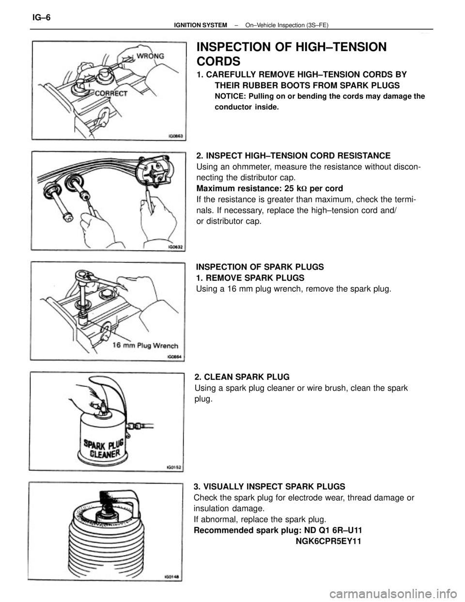
2. INSPECT HIGH±TENSION CORD RESISTANCE
Using an ohmmeter, measure the resistance without discon-
necting the distributor cap.
Maximum resistance: 25 k
� per cord
If the resistance is greater than maximum, check the termi-
nals. If necessary, replace the high±tension cord and/
or distributor cap.
3. VISUALLY INSPECT SPARK PLUGS
Check the spark plug for electrode wear, thread damage or
insulation damage.
If abnormal, replace the spark plug.
Recommended spark plug: ND Q1 6R±U11
NGK6CPR5EY11
INSPECTION OF HIGH±TENSION
CORDS
1. CAREFULLY REMOVE HIGH±TENSION CORDS BY
THEIR RUBBER BOOTS FROM SPARK PLUGS
NOTICE: Pulling on or bending the cords may damage the
conductor inside.
INSPECTION OF SPARK PLUGS
1. REMOVE SPARK PLUGS
Using a 16 mm plug wrench, remove the spark plug.
2. CLEAN SPARK PLUG
Using a spark plug cleaner or wire brush, clean the spark
plug.
± IGNITION SYSTEMOn±Vehicle Inspection (3S±FE)IG±6
Page 1843 of 2389
.
6.")
INSPECTION OF SPARK PLUGS
NOTICE:
wNever use a wire brush for cleaning
wNever attempt to adjust the electrode gap on used
spark plug.
wSpark plug should be replaced every 100,000 km
I60,000 miles).
6. If not using a megger:
(a) Quickly race the engine to 4,000 rpm five times.
(b) Remove the spark plug.
(See step 2 on page IG±11)
(C) Visually check the spark plug.
If the electrode is dry ... Okay
If the electrode is wet ... Proceed to step 3 INSPECTION OF HIGH±TENSION CORDS
1. CAREFULLY REMOVE HIGH±TENSION CORDS BY
THEIR RUBBER BOOTS FROM SPARK PLUGS
NOTICE: Pulling on or bending the cords may damage the
conductor inside.
1. INSPECT ELECTRODE
A. If using a megger (insulation resistance motor):
Measure the insulation resistance.
Correct insulation resistance: 10 M
� or more
If the resistance is less than specified, proceed step 2. 2. INSPECT HIGH±TENSION CORD RESISTANCE
Using an ohmmeter, measure the resistance.
Maximum resistance: 25 k
� per cord
If the resistance is greater than maximum, replace the high±
tension cord.
± IGNITION SYSTEMOn±Vehicle Inspection (2VZ±FE)IG±10
Page 1912 of 2389
 or asterisk (*) are required under the terms of the Emission Control Systems Warranty. See Owners Guide or Warranty Booklet
for complete warranty informat")
Maintenance services indicated by a star (*) or asterisk (*) are required under the terms of the Emission Control Systems Warranty. See Owner's Guide or Warranty Booklet
for complete warranty information.
* For vehicles sold in California
* For vehicles sold outside California
(1) Applicable to vehicles operated under conditions of extensive idling and /or low speed driving for long distances such as police, taxi or door±to±door delivery use.
(2) Applicable when operating mainly on dusty roads. If not, follow SCHEDULE B.
(3) Includes inspection of fuel tank band and vapor vent system.
(4) Also applicable to lining drum for parking brake.
(5) Check for leakage.
(6) Check for oil leaks from steering gear housing.
(7) Applicable only when operating mainly on rough, muddy roads. The applicable parts are listed below. For other usage conditions, refer to SCHEDULE B.
w
Front and rear suspension member to body
w
0 Strut bar bracket to body bolts
w
Bolts for sheet installation
MAINTENANCE SCHEDULESCHEDULE A
CONDITIONS:
wTowing a trailer, using a camper or car top carrier.
wRepeated short trips less than 5 miles (8 km) and outside temperatures remain below freezing.
wExtensive idling and/or low speed driving for a long distance such as police, taxi or door±to±door delivery use.
wOperating on dusty, rough, muddy or salt spread roads.Maintenance operations: A = Check and adjust if necessary;
R = Replace, change or lubricate;
I = Inspect and correct or replace if necessary
Maintenance services beyond 60,000 miles (96,000 km) should continue to be performed at the same intervals shown for each
maintenance schedule.
Service interval
(Odometer reading or
months, whichever
comes first)
Maintenance items
Manual transaxle, automatic transaxle
and differential Brake pads and discs (Front and rear)
Bolts and nuts on chassis and bodyExhaust pipes and mountings
Steering gear housing oily Brake line pipes and hosesFuel lines and connections
Ball joints and dust coversEngine oil and oil filter
Spark plugs (platinum tipped)MA±4 (item 2)
MA±6 (item 6)
Brake linings and drumsFuel tank cap gasket
Drive shaft boots
MA±14 item 221 MA±10 (item 20) MA±5 (item 3,4)
Steering linkageMA±7 (item 12)
MA±8 (item 14) Valve clearance
MA±8 (item 16)
MA±9 (item 19) MA±7 (item 13) MA±7 (item 11
MA±7 (item 10)
MA±9 (item 18) Charcoal canister
MA±9 (item 17) MA±8 (item 151
See page
(item No.)
Engine coolant
MA±6 (item 9) MA±4 (item 1)
MA±4 (item 2)
MA±5 (item 5)
MA±8 (item 8) AAA±6 (item 7)
Air filter¿21*
Spark plugsTiming belt
Drive belts
IGNITION
CHASSIS BRAKESENGINESystem
EVAP FUEL
± MAINTENANCEMaintenance ScheduleMA±2
Page 1913 of 2389
 or asterisk (*) are required under the terms of the Emission Control Systems Warranty.
See Owners Guide or Warranty
Booklet for complete warranty informat")
Maintenance services indicated by a star (*) or asterisk (*) are required under the terms of the Emission Control Systems Warranty.
See Owner's Guide or Warranty
Booklet for complete warranty information.
� For vehicles sold in California
* For vehicles sold outside California
(1) Includes inspection of fuel tank band and vapor vent system.
(2) Also applicable to drum lining for parking brake.
(3) Check for leakage.
(4) Check for oil leaks from steering gear housing.
(5) The applicable part are listed below
wFront and rear suspension member to body
wStrut bar bracket to body bolts
wBolts for sheet installation
Maintenance service beyond 60,000 miles (96,000 km) should continue to be performed at the same intervals shown
for each maintenance schedule.
SCHEDULE BCONDITIONS: Conditions other than those listed for SCHEDULE A.
Service interval
(Odometer reading or
months, whichever
comes first)
Maintenance items
Manual transaxle, automatic
transaxle and differential (3) Brake pads and discs (Front and rearBolts and nuts on chassis and body 17)Exhaust pipes and mountings
Steering gear housing oil 1s) Brake linings and drums (4)
Brake line pipes and hoses Fuel lines and connections (31
Ball joints and dust covers Engine oil and oil filterSpark plugs (platinum tippedFuel tank cap gasket
MA±14 (item 22) MA±10 (item 20)
Charcoal canister
Steering linkage
Drive shaft boots
MA±7 (item 11)
MA±9 (item 19) MA±9 (item 18) MA±7 (item 13) MA±7 (item 10)
MA±8 (item 14) MA±7 (item 12)
MA±8 (item 16) MA±8 (item 15) See page
(item No.)
Engine coolant
MA±9 (item 17)
Valve clearance
MA±6 (item 8) MA±4 (item 2)
MA±6 (item 9) MA±6 (item 7)
MA±6 (item 7)
MA±5 (item 5) MA±5 (item 4)
Drive belts
Air filterSpark plugs
IGNITION
CHASSISBRAKES ENGINESystem
EVAPFUEL
± MAINTENANCEMaintenance ScheduleMA±3
Page 1917 of 2389
 Visually check that the air cleaner element is not ex-
cessively, damaged or oily.
If necessary, replace the air cleaner element.
(b) Clean the element with compressed air.
F")
3. INSPECT AIR FILTER
(a) Visually check that the air cleaner element is not ex-
cessively, damaged or oily.
If necessary, replace the air cleaner element.
(b) Clean the element with compressed air.
First blow from the inside thoroughly, then blow off
the outside of the element.
4. REPLACE AIR FILTER
Replace the air cleaner element with a new one.
5. REPLACE SPARK PLUGS
(a) Disconnect the spark plug cords at the rubber boot. DO
NOT pull on the cords.
(d) 2VZ±FE)
Check the electrode gap of new spark plugs.
Correct electrode gap: 1.1 mm (0.043 in.)
Recommended spark plugs: ND PQ20R
NGK BCPR6EP11
HINT: If adjusting the gap of a new plug, bend only the
base of the ground electrode. DO NOT touch the tip.
Never attempt to adjust the gap on a used plug.(c) PS±FE)
Adjust the electrode gap of new spark plugs.
Correct electrode gap: 1.1 mm (0.043 in.)
Recommended spark plugs: ND Q1 6R±U1 1
NGK BCPR5EY11
(b) Using a 16 mm plug wrench, remove the spark plugs.
± MAINTENANCEMaintenance OperationsMA±5
 Remove union bolt, and disconnect the brake hose from
the disc brake caliper.
(b) Drain the brake fluid into a container.
3. REMOV")