Page 1921 of 2389

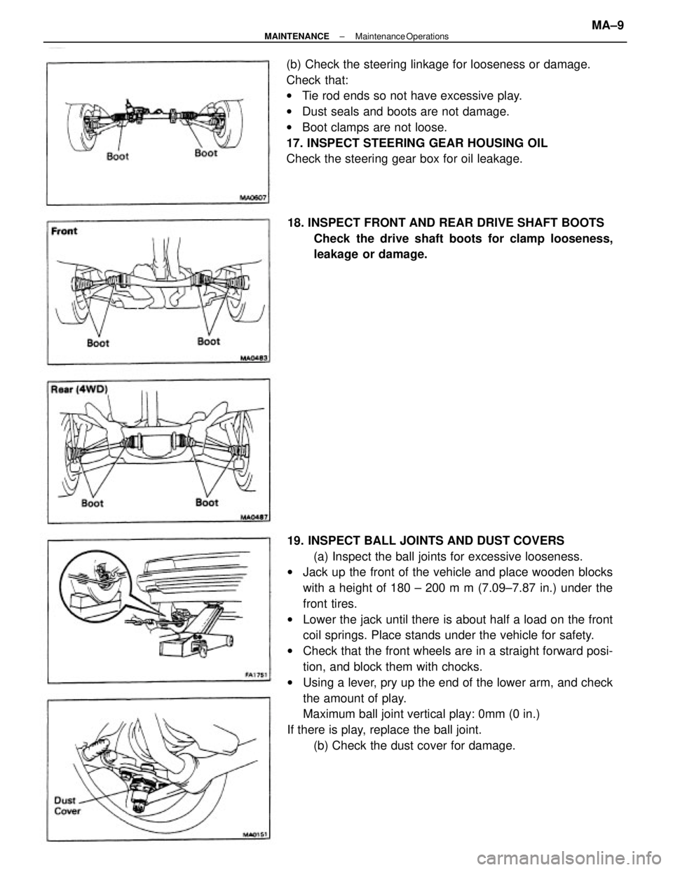
19. INSPECT BALL JOINTS AND DUST COVERS
(a) Inspect the ball joints for excessive looseness.
wJack up the front of the vehicle and place wooden blocks
with a height of 180 ± 200 m m (7.09±7.87 in.) under the
front tires.
wLower the jack until there is about half a load on the front
coil springs. Place stands under the vehicle for safety.
wCheck that the front wheels are in a straight forward posi-
tion, and block them with chocks.
wUsing a lever, pry up the end of the lower arm, and check
the amount of play.
Maximum ball joint vertical play: 0mm (0 in.)
If there is play, replace the ball joint.
(b) Check the dust cover for damage. (b) Check the steering linkage for looseness or damage.
Check that:
wTie rod ends so not have excessive play.
wDust seals and boots are not damage.
wBoot clamps are not loose.
17. INSPECT STEERING GEAR HOUSING OIL
Check the steering gear box for oil leakage.
18. INSPECT FRONT AND REAR DRIVE SHAFT BOOTS
Check the drive shaft boots for clamp looseness,
leakage or damage.
± MAINTENANCEMaintenance OperationsMA±9
Page 1944 of 2389
35. REMOVE NO. 1 HUB SLEEVE ASSEMBLY, FIRST
GEAR, SYNCHRONIZER RING, NEEDLE ROLLER
BEARING AND THRUST WASHER
(a) Using a press, remove No. 1 hub sleeve, 1 st gear and
synchronizer ring.
(b) Remove the needle roller bearing and thrust washer.
36. DISASSEMBLE SHIFT AND SELECT LEVER
ASSEMBLY
(a) Remove the lever lock pin and nut.
(b) Remove the control shift lever.
(c) Remove the dust boot.
(d) Remove the control shaft cover.(b) Using a press, remove the 3rd driven gear and
2nd gear.
(c) Remove the needle roller bearing, spacer and
synchronizer ring.
34. REMOVE SNAP RING
Using two screwdrivers and a hammer, tap out the snap
ring.
(e) Remove the E±ring.
± MANUAL TRANSAXLES51 TransmissionMT±16
Page 1966 of 2389
39. INSTALL SHIFT AND SELECT LEVER ASSEMBLY
(a) Apply seal packing to the underside of the flanged portion of
the control shaft cover.
Seal packing: Part No. 08826±00090, THREE BOND
1281 or equivalent
(b) Install the shift and select lever assembly and torque the con-
trol shaft cover. ._
Torque: 375 kg±cm (27 ft±Ib, 37 N±m)
(h) Install the control shaft cover and dust boot.
HINT: Make sure to install the boot in correct direction.
Position the air bleed of the boot downward. (f) Install No. 2 shift inner lever, spring and reverse
restrict pin holder.
Install the control shift lever and insert the lever lock
pin to the lever. Install the washer and lock nut.(g) Install the E±ring.
± MANUAL TRANSAXLES51 TransmissionMT±35
Page 2010 of 2389
INSPECTION AND REPLACEMENT OF SHIFT
AND SELECT LEVER ASSEMBLY
IF NECESSARY, REPLACE CONTROL SHAFT COVER OIL
SEAL
(a) Using a screwdriver, pry out the oil seal. 5. REMOVE CONTROL SHAFT COVER AND DUST BOOT
(a) Remove the control shaft cover with dust boot from the
shaft.
(b) Remove the dust boot from the control shaft cover.
(b) Using SST, drive in a new oil seal.
SST 09620±30010 (09627±30010, 09631±00020)
Drive in depth: 0.5
+ 0.5 mm (0.020 + 0.020 in.)
(c) Coat the oil seal lip with MP grease. 4. REMOVE SNAP RING
Using two screwdrivers and a hammer, remove the
snap ring.
± MANUAL TRANSAXLEComponent PartsMT±81
Page 2011 of 2389
ASSEMBLY OF SHIFT AND SELECT
LEVER ASSEMBLY
(See page MT±79)
1. COAT SHAFT WITH MP GREASE, AS SHOWN
2. INSTALL DUST BOOT AND CONTROL SHAFT COVER
(a) Install the dust boot to the control shaft cover as
shown.
3. INSTALL SNAP RING
Using a brass bar and hammer, instal! the snap ring.(b) Install the control shaft to the control shaft cover.
± MANUAL TRANSAXLEComponent PartsMT±82
Page 2062 of 2389
2. REMOVE DIFFERENTIAL SIDE GEAR INTERMEDIATE
SHAFT
(a) Screw in a suitable bolt with washer into the side gear
intermediate shaft.
(b) Using SST, remove the side gear intermediate shaft.
SST 09910±00015
REMOVAL OF COMPONENT PARTS
(See pages MT± 118 to MT± 120)
1. REMOVE TRANSFER ASSEMBLY
(a) Remove the three bolts and five nuts.
(b) Using a plastic hammer, remove the transfer assembly
from the transaxle.
B. REMOVE SPEEDOMETER DRIVEN GEAR
6. REMOVE NO.2 SELECTING BELLCRANK WITH
SELECTING BELLCRANK SUPPORT 4. REMOVE BACK±UP LIGHT SWITCH
(a) Remove the back±up light switch.
(b) Remove the gasket from the back±up light switch. 3. REMOVE RELEASE FORK, BEARING AND BOOT
± MANUAL TRANSAXLERemoval of Component PartsMT±121
Page 2081 of 2389
2. REMOVE SHIFT INTERLOCK PLATE AND NO.1 SHIFT
INNER LEVER
(a) Using a pin punch and hammer, drive out the slotted
spring pin.
(b) Remove the shift inter plate and No. 1 shift inner lever
from the shaft.
(e) Remove the shift interlock plate cover and No. 1 shift
inner lever from the shift interlock plate.
3. REMOVE SELECT INNER LEVER
(a) Using a pin punch and hammer, drive out the slotted
spring pin.
(b) Remove the select inner lever, No.1 compression
spring and No.1 select spring seat.
6. 1F NECESSARY, REPLACE CONTROL SHAFT COVER
OIL SEAL
(a) Using a screwdriver, remove oil seal. 4. REMOVE SNAP RING
Using two screwdrivers and a hammer, remove the
snap ring.
5. REMOVE CONTROL SHAFT COVER AND DUST BOOT
± MANUAL TRANSAXLEComponent Parts (Shift and Select Lever ShaftMT±151
Page 2082 of 2389
(b) Using SST and a hammer, drive in the new oil seal.
SST 09620±30010 (09631±00020, 09627±30010)
Oil seal depth: 0 ± 1.0 mm (0 ± 0.039 in.)
(c) Apply MP grease to the oil seal.
ASSEMBLY OF SHIFT AND SELECT LEVER
SHAFT ASSEMBLY
7. APPLY SHAFT WITH MP GREASE. AS SHOWN
2. INSTALL SHIFT AND SELECT LEVER SHAFT
(a) Install the boot to the control shaft cover, as shown.
(b) Install the shift and select lever shaft to the
control shaft cover.
± MANUAL TRANSAXLEComponent Parts (Shift and Select Lever ShaftMT±152