Page 1039 of 2389

wInjector circuit
wInjector
wOxygen sensor circuit
Oxygen sensor
wECU
wFuel line pressure
wAir flow meter
wWater temp. sensor
wIgnition system During air±fuel ratio feedback
correction, voltage output from the
main oxygen sensor does exceed a
set valve on the lean side and the
rich side continuously for a certain
period.
When air±fuel ratio feedback
compensation valve or adaptive
control value continues at the upper
(lean) or (rich) limit renewed for a
certain period of time.
wInjector circuit
wInjector
wFuel line pressure
Cold start injector
wAir flow meter
wWater temp. sensor
wECU
Open circuit in VC signal or short
circuit between VC and
E2 when idle contacts are closed.wIgnition circuit (+B, IGT,
IGF)
wIgniter
wECU
Open or short circuit i n sub±
oxygen sensor signal (OX2)wIntake air temp. sensor
circuit
wIntake air temp. sensor
wECU No NE signal to ECU when the
engine speed is above 1,000
rpm. This appears when none of the other
codes (11 thru 71) are identified.
No NE or G signal to ECU
within several seconds after engine
is cracked.
wMain oxygen sensor cir-
cuit
wMain oxygen sensor
wECU wDistributor circuit
wDistributor
wStarter signal circuit
wECU
wWater temp. sensor cir-
cuit
wWater temp. sensor
wECU
wSub±oxygen sensor cir-
cuit
wSub±oxygen sensor
wECU
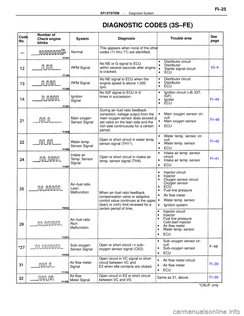
DIAGNOSTIC CODES (3S±FE)
wAir flow meter circuit
wAir flow meter
wECU Open or short circuit in water temp.
sensor signal (TH1^).
Open or short circuit in intake air
temp. sensor signal (THA)
Open circuit in E2 or short circuit
between VC and VS.No IGF signal to ECU 4±5
times in succession.wDistributor circuit
wDistributor
wECU
Intake air
Temp. Sensor
Signal Number of
Check engine
blinks
Air±fuel ratio
Lean
Malfunction
Air±fuel ratio
Rich
MalfunctionMain oxygen
Sensor Signal
Water temp.
Sensor Signal
Sub±oxygen
Sensor Signal
Air flow
Meter SignalAir flow meter
Signal
Same as 31, above.
*CALIF. only Ignition
SignalRPM Signal
RPM SignalTrouble area
DiagnosisSee
page System Code
No.
Normal
FI±42
FI±39FI±48
FI±39F±48FI±41IG±4
FI±44
± EFI SYSTEMDiagnosis SystemFI±25
Page 1041 of 2389

(CALIF.)
wWhen air±fuel ratio feed±
back correction value or adap-
tive control value continues at
the upper (lean)
or lower (rich) limit for a certain
period of time or adaptive con-
trol value is not renewed for a
certain period of time.
wWhen feedback frequency of
air±fuel ratio feed±
back correction or adaptive
control is abnormally
high during feedback condition.
(Others)
wOxygen sensor outputs a lean
signal continuously for several
seconds during air±fuel ratio
feedback correction.
wOpen circuit in oxygen sensor
signal (OX).wWater temp. sensor
wInjector circuit
wInjector
wFuel line pressure
wAir flow meter
wAir intake system
wOxygen sensor circuits
wOxygen sensors
wIgnition system
wECU During air±fuel ratio feedback
correction, voltage output from the
main oxygen sensor does exceed a
set value on the lean side and the
rich side continuously for a certain
period.
Water temp. sensor
wInjector circuit
wInjector
wFuel line pressure
wAir flow meter
wCold start injector
wECU wMain oxygen heater circuit
wMain oxygen sensor heater
wECU wIgniter and ignition coil circuit
wIgniter and ignition coil
wECU
wIntake air temp. sensor circuit
wIntake air temp. sensor
wECU Open or short circuit in main oxygen
sensor heater signal
(HT).No NE signal to ECU when the en-
gine speed is above 1,000
rpm.wDistributor circuit
wDistributor
wStarter signal circuit
wECU
wMain oxygen sensor circuit
wMain oxygen sensor
wECU No NE or G signal to ECU
within 2 seconds after engine has
been cranked.
wWater temp. sensor circuit
wWater temp. sensor
wECU
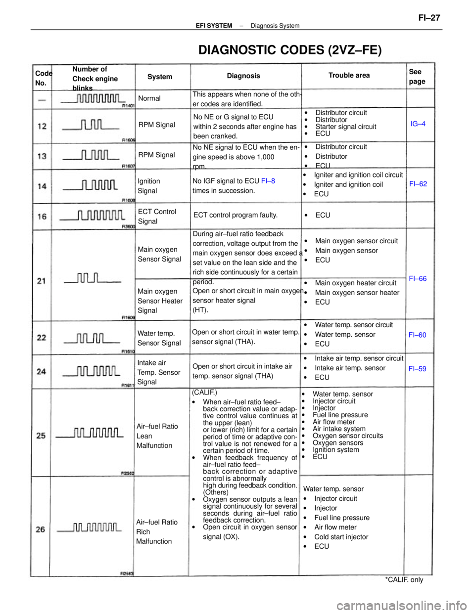
DIAGNOSTIC CODES (2VZ±FE)
Open or short circuit in water temp.
sensor signal (THA).
Open or short circuit in intake air
temp. sensor signal (THA) This appears when none of the oth-
er codes are identified.
wDistributor circuit
wDistributor
wECU
No IGF signal to ECU FI±8
times in succession.
Intake air
Temp. Sensor
Signal
Air±fuel Ratio
Lean
Malfunction Number of
Check engine
blinks
Air±fuel Ratio
Rich
MalfunctionMain oxygen
Sensor Heater
SignalECT control program faulty.
Main oxygen
Sensor Signal
Water temp.
Sensor SignalECT Control
Signal
*CALIF. only Ignition
SignalTrouble area
RPM Signal
RPM SignalDiagnosisSee
page Code
No.System
Normal
wECU
FI±60FI±66
FI±59FI±62IG±4
± EFI SYSTEMDiagnosis SystemFI±27
Page 1047 of 2389
ON±VEHICLE INSPECTION
1. CHECK FUEL PUMP OPERATION
(a) Turn the ignition switch ON.
NOTICE: Do not start the engine.
(b) Using SST, connect terminals +B and FP of the check con-
nector.
SST 09843±18020
(e) Turn the ignition switch OFF.
If there is no pressure, check the following
parts:
wFusible links
wFuses (ER 15 A, IGN 7.5 A)
wER main relay
wFuel pump
wECU
wWiring connections (e) Check that there is pressure in the hose from the fuel
filter.
HINT: At this time, you will hear fuel return noise.
(d) Remove SST.
SST 09843±18020
± EFI SYSTEMFuel System (Fuel Pump)FI±70
Page 1048 of 2389
(f) Install SST (pressure gauge) to the delivery pipe (3S±
FE) or LH delivery pipe (2VZ±FE) with new two gas-
kets and the union bolt.
SST 09268±45012
Torque: 3S±FE 180 kg±cm (13 ft±Ib, 18 N±m)
2VZ±FE 200 kg±cm (14 ft±lb, 20 N ±m)
(g) Wipe off any splattered gasoline.
(h) Reconnect the battery negative H cable. (c) Disconnect the cold start injector connector.
(d) Put a suitable container or shop towel under the cold
start injector pipe (3S±FE) or tube (2VZ±FE).
(e) Remove the union bolt and two gaskets, and discon-
nect the cold start injector tube from the delivery pipe
(3S±FE) or LH delivery pipe (2VZ±FE).
HINT: Slowly loosen the union bolt. 2. CHECK FUEL PRESSURE
(a) Check the battery voltage is above 12 volts.
(b) Disconnect the cable from the negative (±) terminal of the
battery.
± EFI SYSTEMFuel System (Fuel Pump)FI±71
Page 1049 of 2389
(j) Turn the ignition switch ON.
(k) Measure the fuel pressure.
Fuel pressure: 2.7 ± 3.1 kg/cm
2
(38 ± 44 pst, 265 ± 304 kPa)
If pressure is high, replace the fuel pressure regulator.
If pressure is low, check the following parts:
wFuel hoses and connection
wFuel pump
wFuel filter
wFuel pressure regulator
(m) Start the engine. .
(n) Disconnect the vacuum sensing hose from the fuel
pressure regulator, and plug the hose end.
(o) Measure the fuel pressure at idling.
Fuel pressure: 2.7 ± 3.1 kg/cm
2
(38 ± 44 psi, 265 ± 304 kPa) (i) Using SST, connect terminals +B and FP of the check
connector.
SST 09843±18020
(l) Remove SST.
SST 09843±18020
± EFI SYSTEMFuel System (Fuel PumpFI±72
Page 1050 of 2389

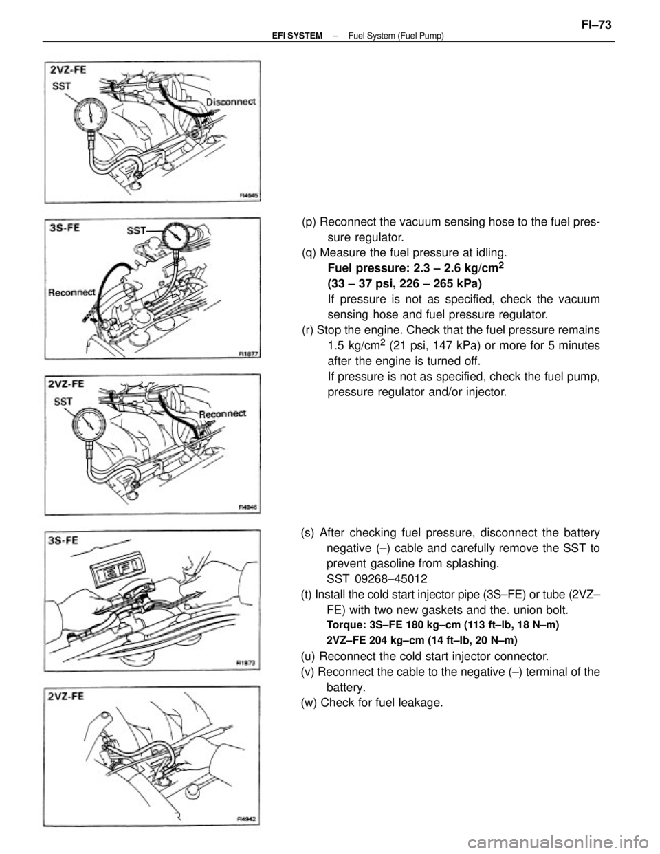
(s) After checking fuel pressure, disconnect the battery
negative (±) cable and carefully remove the SST to
prevent gasoline from splashing.
SST 09268±45012
(t) Install the cold start injector pipe (3S±FE) or tube (2VZ±
FE) with two new gaskets and the. union bolt.
Torque: 3S±FE 180 kg±cm (113 ft±lb, 18 N±m)
2VZ±FE 204 kg±cm (14 ft±Ib, 20 N±m)
(u) Reconnect the cold start injector connector.
(v) Reconnect the cable to the negative (±) terminal of the
battery.
(w) Check for fuel leakage.(p) Reconnect the vacuum sensing hose to the fuel pres-
sure regulator.
(q) Measure the fuel pressure at idling.
Fuel pressure: 2.3 ± 2.6 kg/cm
2
(33 ± 37 psi, 226 ± 265 kPa)
If pressure is not as specified, check the vacuum
sensing hose and fuel pressure regulator.
(r) Stop the engine. Check that the fuel pressure remains
1.5 kg/cm
2 (21 psi, 147 kPa) or more for 5 minutes
after the engine is turned off.
If pressure is not as specified, check the fuel pump,
pressure regulator and/or injector.
± EFI SYSTEMFuel System (Fuel Pump)FI±73
Page 1072 of 2389
Check that there is specified voltage between ECU terminal VF
and body ground.
Check for suction of air into exhaust
system.Check wiring between ECU terminal E1 and body ground.
Check wiring between oxygen sensors and
ECU connectors.There is no voltage between ECU terminals VF and E1.
Check for air leak from air intake system.
Check distributor and ignition system.
Check operation of oxygen sensors. Check cold start injector±.
Replace oxygen sensors.* Rich malfunction only Check fuel pressure.
Check air flow meter.Check spark plugs.Repair or replace.
Repair air suction.
Repair or replace.
Repair or replace. Repair or replace.
Repair or replace.
Repair or replace. Repair or replace. Try another ECU.
Check injectors.
System normal.Repair air leak.
Repair wiring. BAD
BADBADBADBAD
BADBAD
BAD BADBAD
BAD
± EFI SYSTEMTroubleshooting with Volt OhmmeterFI±48
Page 1074 of 2389

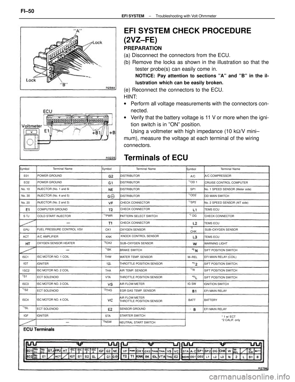
EFI SYSTEM CHECK PROCEDURE
(2VZ±FE)
PREPARATION
(a) Disconnect the connectors from the ECU.
(b) Remove the locks as shown in the illustration so that the
tester probe(s) can easily come in.
NOTICE: Pay attention to sections ºAº and ºBº in the il-
lustration which can be easily broken.
(e) Reconnect the connectors to the ECU.
HINT:
wPerform all voltage measurements with the connectors con-
nected.
wVerify that the battery voltage is 11 V or more when the igni-
tion switch is in ºONº position.
Using a voltmeter with high impedance (10 k
�/V mini±
mum), measure the voltage at each terminal of the wiring
connectors.
AIR FLOW METER
THROTTLE POSITION SENSOR
Terminals of ECU
No. 1 SPEED SENSOR (Meter side)
No. 2 SPEED SENSOR (AlT side)
THROTTLE POSITION SENSOR FUEL PRESSURE CONTROL VSV
THROTTLE POSITION SENSORCRUISE CONTROL COMPUTER
* 1 w/ ECT
*2 CALIF. only KNOCK CONTROL SENSOR PATTERN SELECT SWITCH
OXYGEN SENSOR HEATER
NEUTRAL START SWITCHEGR GAS TEMP. SENSOR INJECTOR (No. 2 and 3)INJECTOR (No. 4 and 5)
SIFT POSITION SWITCH.
ISC MOTOR NO. 3 COILINJECTOR (No. 1 and 6i
ISC MOTOR NO. 1 COIL
ISC MOTOR NO. 4 COILSIFT POSITION SWITCH ISC MOTOR NO. 2 COILWATER TEMP. SENSORSUB±OXYGEN SENSOR
SIFT POSITION SWITCH COLD START INJECTOR
EFI MAIN RELAY (COIL)
SIFT POSITION SWITCHSUB±OXYGEN SENSOR CHECK CONNECTOR
COMPUTER GROUND
CHECK CONNECTORCHECK CONNECTOR CHECK CONNECTOR
AIR TEMP. SENSORA/C COMPRESSOR
SENSOR GROUNDTerminal Name
OXYGEN SENSOROD MAIN SWITCH
STARTER SWITCHIGNITION SWITCH Terminal Name
AIR FLOW METERTerminal Name
POWER GROUND
POWER GROUND
WARNING LIGHT
EFI MAIN RELAY BRAKE SWITCH
EFt MAIN RELAY ECT SOLENOID
ECT SOLENOIDA/C AMPLIFIER
ECT SOLENOIDDISTRIBUTOR
DISTRIBUTOR DISTRIBUTOR
DISTRIBUTOR
TEMS ECU
TEMS ECU
TEMS ECU Symbol Symbol Symbol
BATTERY IGNITER
IGNITER
*2NSW
*1OD2
No. 30 No. 10
No. 20
*1PWR
*2OX2
M±REL
*1OD 1
*2CHK
*2THGIG SW
*1SP2
BATT
*1SL
*1 DG
1S1THW
*1S2
*1BK
ISC4 1SC2 ISC1
ISC3VTAOX1
ACTS TJSP1
THA
STAKNK EO2 E01
IGT
*1R A/C
EPU
1
L
IGF
± EFI SYSTEMTroubleshooting with Volt OhmmeterFI±50