Page 1108 of 2389

3. (A/T)
DISCONNECT THROTTLE CABLE FROM THROTTLE
BODY AND BRACKET
4. DISCONNECT ACCE")
REMOVAL OF INJECTORS
1. DISCONNECT CABLE FROM NEGATIVE TERMINAL
OF BATTERY
2. DRAIN ENGINE COOLANT (See page CO±5)
3. (A/T)
DISCONNECT THROTTLE CABLE FROM THROTTLE
BODY AND BRACKET
4. DISCONNECT ACCELERATOR CABLE AND BRACKET
FROM THROTTLE BODY AND AIR INTAKE CHAMBER
5. REMOVE AIR CLEANER CAP, AIR FLOW METER AND
AIR CLEANER HOSE
(a) Disconnect the. air flow meter connector.
(b) Disconnect the air hoses.
(e) Loosen the air cleaner hose clamp bolt.
(d) Disconnect the air cleaner cap clips.
(e) Remove the air cleaner cap and air flow meter
together with the air cleaner hose.
6. DISCONNECT HOSES AND CONNECTORS
(a) PCV hoses
(b) Vacuum sensing hose
(e) Water by±pass hoses
(d) Fuel pressure control VSV hose
(e) Emission control vacuum hoses
(f) ISC connector
(g) Throttle position sensor connector
(h) (CALIF. only)
EGR gas temp. sensor connector
7. REMOVE NO. 1 RH ENGINE MOUNTING STAY
Remove the three bolts and mounting stay.
8. DISCONNECT COLD START INJECTOR CONNECTOR
9. DISCONNECT COLD START INJECTOR TUBE
(See step 3 on page FI±81 )
± EFI SYSTEMFuel System (Injectors (2VZ±FE))FI±94
Page 1109 of 2389
 Brake booster vacuum hose
(b) PS vacuum and air hoses
(c) Cruise control vacuum hose
(d) Ground strap connector
(e) Wire harness clamp
Remove the nut, and disconnect")
10. DISCONNECT HOSES AND PARTS
(a) Brake booster vacuum hose
(b) PS vacuum and air hoses
(c) Cruise control vacuum hose
(d) Ground strap connector
(e) Wire harness clamp
Remove the nut, and disconnect the wire harness clamp.
(f) Fuel pressure control VSV hose.
11. DISCONNECT WIRE HARNESS CLAMP
Remove the nut and disconnect the wire harness.
12. DISCONNECT EGR PIPE
13. REMOVE NO.1 ENGINE HANGER AND AIR INTAKE
CHAMBER STAY
(a) Remove the two bolts and No.1 engine hanger.
(b) Remove the bolt, and disconnect the air intake chamber
stay from air intake chamber.
14. REMOVE AIR INTAKE CHAMBER
Remove the two bolts, nuts, air intake chamber and gasket.
15. DISCONNECT CONNECTORS
(a) Cold start injector connector
(b) Water temperature sensor connector
(c) Six injector connectors
16. DISCONNECT WIRE HARNESS CLAMPS FROM LH
DELIVERY PIPE
Disconnect the three wire harness clamp.
17. DISCONNECT FUEL INLET AND TWO RETURN
HOSES
(a) Disconnect the fuel return hoses from the fuel pressure reg-
ulator and No.1 fuel pipe.
(b) Disconnect the fuel inlet hose from the fuel filter.
18. REMOVE NO.2 FUEL PIPE
Remove the two union bolts, four gaskets and No.2 fuel
pipe.
± EFI SYSTEMFuel System (Injectors (2VZ±FE))FI±95
Page 1110 of 2389
 Remove the two bolts and LH delivery pipe together with
three injectors.
NOTICE:. Be careful not to drop the injectors, when remov-
ing the delivery pipe.")
19. REMOVE DELIVERY PIPES AND INJECTORS
(a) Remove the two bolts and LH delivery pipe together with
three injectors.
NOTICE:. Be careful not to drop the injectors, when remov-
ing the delivery pipe.
(b) Remove the three bolts and RH delivery pipe with the
No. 1 fuel pipe and three injectors.
NOTICE: Be careful not to drop the injectors, when remov-
ing the delivery pipe.
(c) Pull out the six injectors from the delivery pipes.
(d) Remove the six insulators and four spacers from the intake
manifold.
(a) Disconnect the fuel hose from the fuel filter outlet.
(b) Connect SST (union and hose) to the fuel fitter outlet
with two new gaskets and the union bolt.
SST 49268±41045 (90405±09015)
HINT: Use the vehicle's fuel filter.
(e) Remove the pressure regulator. (See page FI±86)
(d) Connect the fuel return hose and SST (hose) to the
pressure regulator with SST (union).
SST 09268±41045 (09268±41060)
INSPECTION OF INJECTORS
1. INSPECT INJECTOR INJECTION
NOTICE: Keep clear for sparks during the test.
± EFI SYSTEMFuel System (Injectors (2VZ±FE))FI±96
Page 1113 of 2389

8. CONNECT WIRE HARNESS CLAMP
Connect the wire harness clamp with the nut.
9. INSTALL NO.1 ENGINE HANGER AND AIR INTAKE
CHAMBER STAY
(a) Con")
7. CONNECT EGR PIPE
Torque: 800 kg±cm (58 ft±1b, 78 N±m)
8. CONNECT WIRE HARNESS CLAMP
Connect the wire harness clamp with the nut.
9. INSTALL NO.1 ENGINE HANGER AND AIR INTAKE
CHAMBER STAY
(a) Connect the air intake chamber stay with the two bolts.
Torque: 380 kg±cm (27 ft±Ib,37 N±m)
(b) Install the No.1 engine hanger with the two bolts.
Torque: 380 kg±cm (27 it±Ib,37 N±m)
10. CONNECT HOSES AND PARTS
(a) Wire harness clamp
Connect the wire harness clamp with the nut.
(b) Brake booster vacuum hose
(c) PS vacuum and air hoses
(d) Cruise control vacuum hose
(e) Ground strap connector
(f) Fuel pressure control VSV hose2. INSTALL NO.2 FUEL PIPE
Install the No.2 fuel pipe with four new gaskets and the union
bolts as shown in the illustration.
Torque: 330 kg±cm (24 ft±Ib, 32 N±m)
3. CONNECT FUEL INLET AND RETURN HOSES
(a) Connect the inlet hose to the fuel filter with two new gaskets
and union bolt.
(b) Connect the two return hoses to the pressure regulator and
No.1 fuel pipe.
4. CONNECT THREE WIRE HARNESS CLAMPS TO LH
DELIVERY PIPE
5. CONNECT CONNECTORS
(a) Six injector connectors
(b) Cold start injector connector
(e) Water temperature connector
6. INSTALL AIR INTAKE CHAMBER
Install a new gasket and the air intake chamber with the two
bolts and nuts.
Torque: 440 kg±cm (32 ft±lb, 43 N±m)
± EFI SYSTEMFuel System (Injectors (2VZ±FE))FI±99
Page 1114 of 2389

CONNECT THROTTLE CABLE TO THROTTLE BODY
AND BRACKET, AND ADJUST IT
18. FILL WITH COOLANT (See page CO±5)
19")
16. CONNECT ACCELERATOR CABLE AND BRACKET TO
THROTTLE BODY AND AIR INTAKE CHAMBER
17. (A/T)
CONNECT THROTTLE CABLE TO THROTTLE BODY
AND BRACKET, AND ADJUST IT
18. FILL WITH COOLANT (See page CO±5)
19. CONNECT CABLE TO NEGATIVE TERMINAL OF
BATTERY 14. CONNECT CONNECTORS AND HOSES
(a) ISC connector
(b) Throttle position sensor connector
(c) (CALIF. only)
EGR gas temp. sensor connectors
(d) PCV hoses
(e) Vacuum sensing hoses
(f) Water by±pass hoses
(g) Fuel pressure VSV hose
(h) Emission control vacuum hoses
15. INSTALL AIR CLEANER CAP, AIR FLOW METER AND
AIR CLEANER HOSE
(a) Connect the air cleaner hose, and install the air
cleaner cap and air flow meter with the four clips.
(b) Tighten the air cleaner hose clamp bolt.
(c) Connect the air hoses.
(d) Connect the air flow meter connector. 11. CONNECT COLD START INJECTOR TUBE
(See step 2 on page FI±83)
12. CONNECT COLD START INJECTOR CONNECTOR
13. INSTALL NO. 1 RH ENGINE MOUNTING STAY
Install the mounting stay with the three bolts.
Torque: 530 kg±cm (38 ft±Ib, 52 N±m)
± EFI SYSTEMFuel System (Injectors (2VZ±FE))FI±100
Page 1141 of 2389
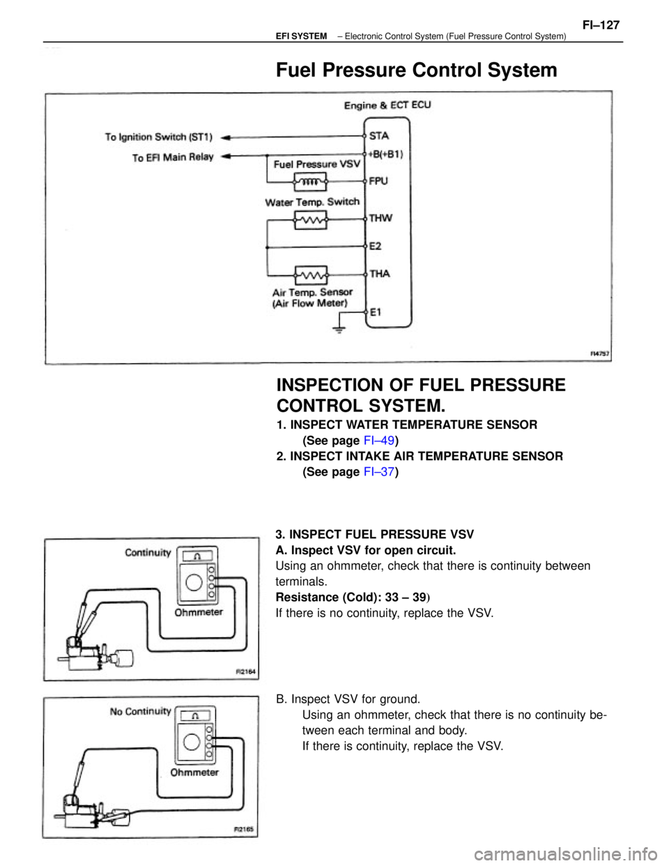
3. INSPECT FUEL PRESSURE VSV
A. Inspect VSV for open circuit.
Using an ohmmeter, check that there is continuity between
terminals.
Resistance (Cold): 33 ± 39�
If there is no continuity, replace the VSV.
INSPECTION OF FUEL PRESSURE
CONTROL SYSTEM.
1. INSPECT WATER TEMPERATURE SENSOR
(See page FI±49)
2. INSPECT INTAKE AIR TEMPERATURE SENSOR
(See page FI±37)
B. Inspect VSV for ground.
Using an ohmmeter, check that there is no continuity be-
tween each terminal and body.
If there is continuity, replace the VSV.
Fuel Pressure Control System
± EFI SYSTEMElectronic Control System (Fuel Pressure Control System)FI±127
Page 1142 of 2389
(b) Apply battery voltage across the terminals
(c) Check that air flows from pipe E to filter.
If operation is not as specified, replace the VSV. C. Inspect VSV operation
(a) Check that air flow from pipes E to G.
± EFI SYSTEMElectronic Control System (Fuel Pressure Control System))FI±128
Page 1157 of 2389

INSPECTION OF FUEL VAPOR
LINES, FUEL TANK AND TANK CAP
1. VISUALLY INSPECT LINES AND CONNECTIONS
Look for loose connections, sharp bends or damage.
2. VISUALLY INSPECT FUEL TANK
Look for deformation, cracks or fuel leakage.
3. VISUALLY INSPECT FUEL TANK CAP
Check if the cap and/or gasket are deformed or damaged if
necessary, repair or replace. the cap.
To reduce HC emission, evaporated fuel from the fuel tank is routed through the charcoal canister to the intake manifold for
combustion in the cylinders.
FUEL EVAPORATIVE EMISSION CONTROL (EVAP) SYSTEM
HC from canister is led into air
intake chamber.NC from tank is absorbed into
the canister.
HC from tank is absorbed into
the canister.
Air is led into the fuel tank. Throttle Valve
OpeningEvaporated Fuel (HO
High pressure
in tankAbove
54°C(129° F )
High vacuum
in tankBelow
35°C (95°F)Canister Check Valve
Check
Valve in
Cap Coolant
Temp.
svsv
± EMISSION CONTROL SYSTEMS (3S±FE)Fuel Evaporative Emission Control (EVAP) SystemEC±5
 Apply battery voltage across the terminals
(c) Check that air flows from pipe E to filter.
If operation is not as specified, replace the VSV. C. Inspect VSV operation
(a) Check that air flow from")