1986 TOYOTA CAMRY V20 fuel pressure
[x] Cancel search: fuel pressurePage 1158 of 2389
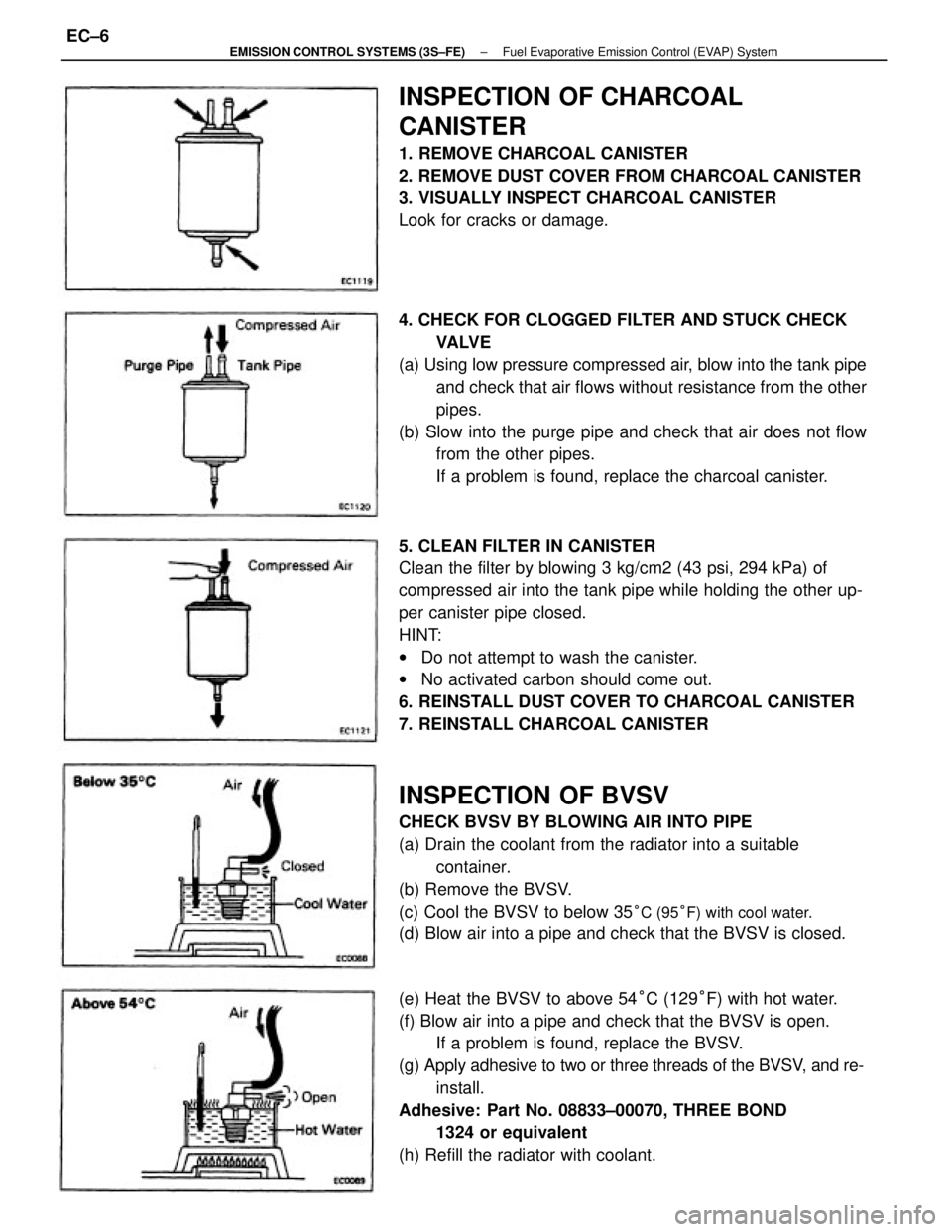
5. CLEAN FILTER IN CANISTER
Clean the filter by blowing 3 kg/cm2 (43 psi, 294 kPa) of
compressed air into the tank pipe while holding the other up-
per canister pipe closed.
HINT:
wDo not attempt to wash the canister.
wNo activated carbon should come out.
6. REINSTALL DUST COVER TO CHARCOAL CANISTER
7. REINSTALL CHARCOAL CANISTER
INSPECTION OF BVSV
CHECK BVSV BY BLOWING AIR INTO PIPE
(a) Drain the coolant from the radiator into a suitable
container.
(b) Remove the BVSV.
(c) Cool the BVSV to below 35
°C (95°F) with cool water.
(d) Blow air into a pipe and check that the BVSV is closed. 4. CHECK FOR CLOGGED FILTER AND STUCK CHECK
VA LV E
(a) Using low pressure compressed air, blow into the tank pipe
and check that air flows without resistance from the other
pipes.
(b) Slow into the purge pipe and check that air does not flow
from the other pipes.
If a problem is found, replace the charcoal canister.
(e) Heat the BVSV to above 54°C (129°F) with hot water.
(f) Blow air into a pipe and check that the BVSV is open.
If a problem is found, replace the BVSV.
(g) Apply adhesive to two or three threads of the BVSV, and re-
install.
Adhesive: Part No. 08833±00070, THREE BOND
1324 or equivalent
(h) Refill the radiator with coolant.
INSPECTION OF CHARCOAL
CANISTER
1. REMOVE CHARCOAL CANISTER
2. REMOVE DUST COVER FROM CHARCOAL CANISTER
3. VISUALLY INSPECT CHARCOAL CANISTER
Look for cracks or damage.
± EMISSION CONTROL SYSTEMS (3S±FE)Fuel Evaporative Emission Control (EVAP) SystemEC±6
Page 1170 of 2389
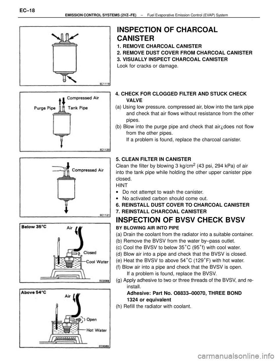
5. CLEAN FILTER IN CANISTER
Clean the filter by blowing 3 kg/cm
2 (43 psi, 294 kPa) of air
into the tank pipe while holding the other upper canister pipe
closed.
HINT
wDo not attempt to wash the canister.
wNo activated carbon should come out.
6. REINSTALL DUST COVER TO CHARCOAL CANISTER
7. REINSTALL CHARCOAL CANISTER
INSPECTION OF BVSV CHECK BVSV
BY BLOWING AIR INTO PIPE
(a) Drain the coolant from the radiator into a suitable container.
(b) Remove the BVSV from the water by±pass outlet.
(c) Cool the BVSV to below 35°C (95°f) with cool water.
(d) Blow air into a pipe and check that the BVSV is closed.
(e) Heat the BVSV to above 54°C (129°F) with hot water.
(f) Blow air into a pipe and check that the BVSV is open.
If a problem is found, replace the BVSV.
(g) Apply adhesive to two or three threads of the BVSV, and re-
install.
Adhesive: Part No. O8833±00070, THREE BOND
1324 or equivalent
(h) Refill the radiator with coolant.
INSPECTION OF CHARCOAL
CANISTER
1. REMOVE CHARCOAL CANISTER
2. REMOVE DUST COVER FROM CHARCOAL CANISTER
3. VISUALLY INSPECT CHARCOAL CANISTER
Look for cracks or damage.
4. CHECK FOR CLOGGED FILTER AND STUCK CHECK
VA LV E
(a) Using low pressure. compressed air, blow into the tank pipe
and check that air flows without resistance from the other
pipes.
(b) Blow into the purge pipe and check that air¿does not flow
from the other pipes.
If a problem is found, replace the charcoal canister.
± EMISSION CONTROL SYSTEMS (2VZ±FE)Fuel Evaporative Emission Control (EVAP) SystemEC±18
Page 1186 of 2389
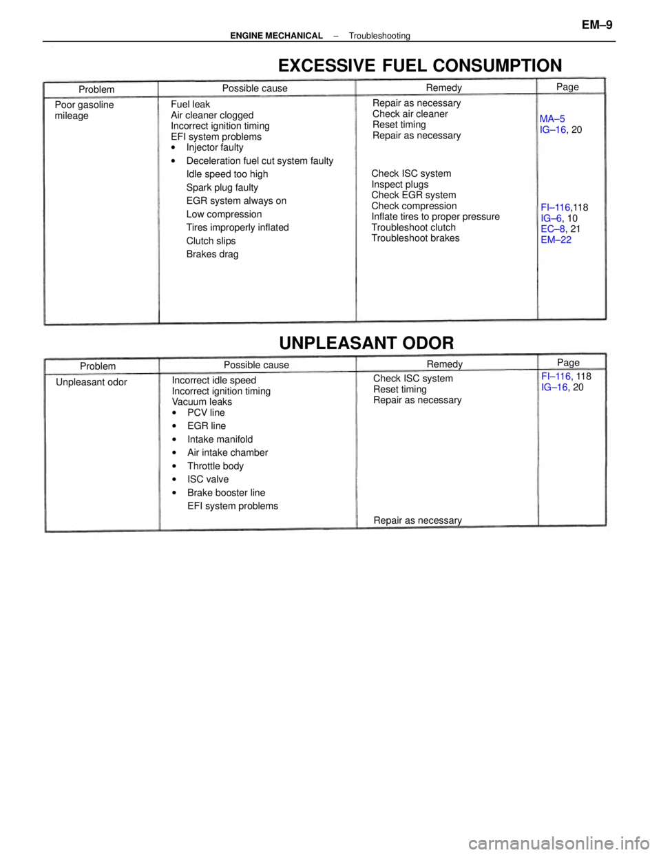
Fuel leak
Air cleaner clogged
Incorrect ignition timing
EFI system problems
wInjector faulty
wDeceleration fuel cut system faulty
Idle speed too high
Spark plug faulty
EGR system always on
Low compression
Tires improperly inflated
Clutch slips
Brakes drag
Incorrect idle speed
Incorrect ignition timing
Vacuum leaks
wPCV line
wEGR line
wIntake manifold
wAir intake chamber
wThrottle body
wISC valve
wBrake booster line
EFI system problemsCheck ISC system
Inspect plugs
Check EGR system
Check compression
Inflate tires to proper pressure
Troubleshoot clutch
Troubleshoot brakesRepair as necessary
Check air cleaner
Reset timing
Repair as necessary
EXCESSIVE FUEL CONSUMPTION
Check ISC system
Reset timing
Repair as necessaryFI±116,118
IG±6, 10
EC±8, 21
EM±22
UNPLEASANT ODOR
Poor gasoline
mileage
FI±116, 118
IG±16, 20
Repair as necessaryMA±5
IG±16, 20
Unpleasant odorPossible cause Possible cause
Problem
ProblemRemedy
RemedyPage Page
± ENGINE MECHANICALTroubleshootingEM±9
Page 1198 of 2389
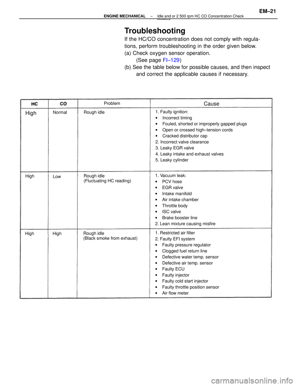
Troubleshooting
If the HC/CO concentration does not comply with regula-
tions, perform troubleshooting in the order given below.
(a) Check oxygen sensor operation.
(See page FI±129)
(b) See the table below for possible causes, and then inspect
and correct the applicable causes if necessary.
1. Faulty ignition:
wIncorrect timing
wFouled, shorted or improperly gapped plugs
wOpen or crossed high±tension cords
wCracked distributor cap
2. Incorrect valve clearance
3. Leaky EGR valve
4. Leaky intake and exhaust valves
5. Leaky cylinder
1. Restricted air filter
2. Faulty EFI system
wFaulty pressure regulator
wClogged fuel return line
wDefective water temp. sensor
wDefective air temp. sensor
wFaulty ECU
wFaulty injector
wFaulty cold start injector
wFaulty throttle position sensor
wAir flow meter 1. Vacuum leak:
wPCV hose
wEGR valve
wIntake manifold
wAir intake chamber
wThrottle body
wISC valve
wBrake booster line
2. Lean mixture causing misfire
Rough idle
(Black smoke from exhaust)Rough idle
(Fluctuating HC reading) Rough idleProblem
Normal
Cause
High
High
HighHigh
Low
± ENGINE MECHANICALIdle and or 2 500 rpm HC CO Concentration CheckMethod
EM±21
Page 1199 of 2389
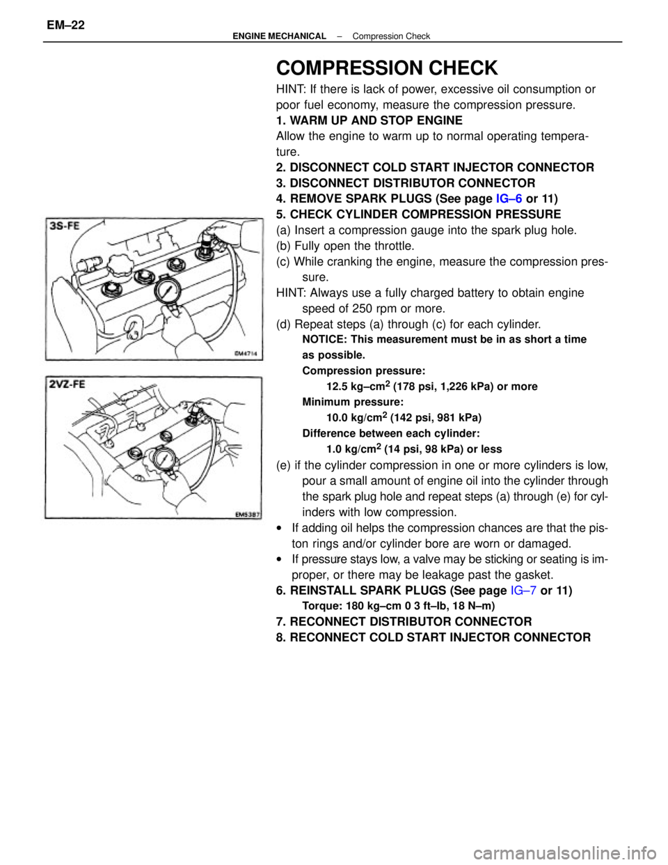
COMPRESSION CHECK
HINT: If there is lack of power, excessive oil consumption or
poor fuel economy, measure the compression pressure.
1. WARM UP AND STOP ENGINE
Allow the engine to warm up to normal operating tempera-
ture.
2. DISCONNECT COLD START INJECTOR CONNECTOR
3. DISCONNECT DISTRIBUTOR CONNECTOR
4. REMOVE SPARK PLUGS (See page IG±6 or 11)
5. CHECK CYLINDER COMPRESSION PRESSURE
(a) Insert a compression gauge into the spark plug hole.
(b) Fully open the throttle.
(c) While cranking the engine, measure the compression pres-
sure.
HINT: Always use a fully charged battery to obtain engine
speed of 250 rpm or more.
(d) Repeat steps (a) through (c) for each cylinder.
NOTICE: This measurement must be in as short a time
as possible.
Compression pressure:
12.5 kg±cm
2 (178 psi, 1,226 kPa) or more
Minimum pressure:
10.0 kg/cm
2 (142 psi, 981 kPa)
Difference between each cylinder:
1.0 kg/cm
2 (14 psi, 98 kPa) or less
(e) if the cylinder compression in one or more cylinders is low,
pour a small amount of engine oil into the cylinder through
the spark plug hole and repeat steps (a) through (e) for cyl-
inders with low compression.
wIf adding oil helps the compression chances are that the pis-
ton rings and/or cylinder bore are worn or damaged.
wIf pressure stays low, a valve may be sticking or seating is im-
proper, or there may be leakage past the gasket.
6. REINSTALL SPARK PLUGS (See page IG±7 or 11)
Torque: 180 kg±cm 0 3 ft±Ib, 18 N±m)
7. RECONNECT DISTRIBUTOR CONNECTOR
8. RECONNECT COLD START INJECTOR CONNECTOR
± ENGINE MECHANICALCompression CheckEM±22
Page 1254 of 2389
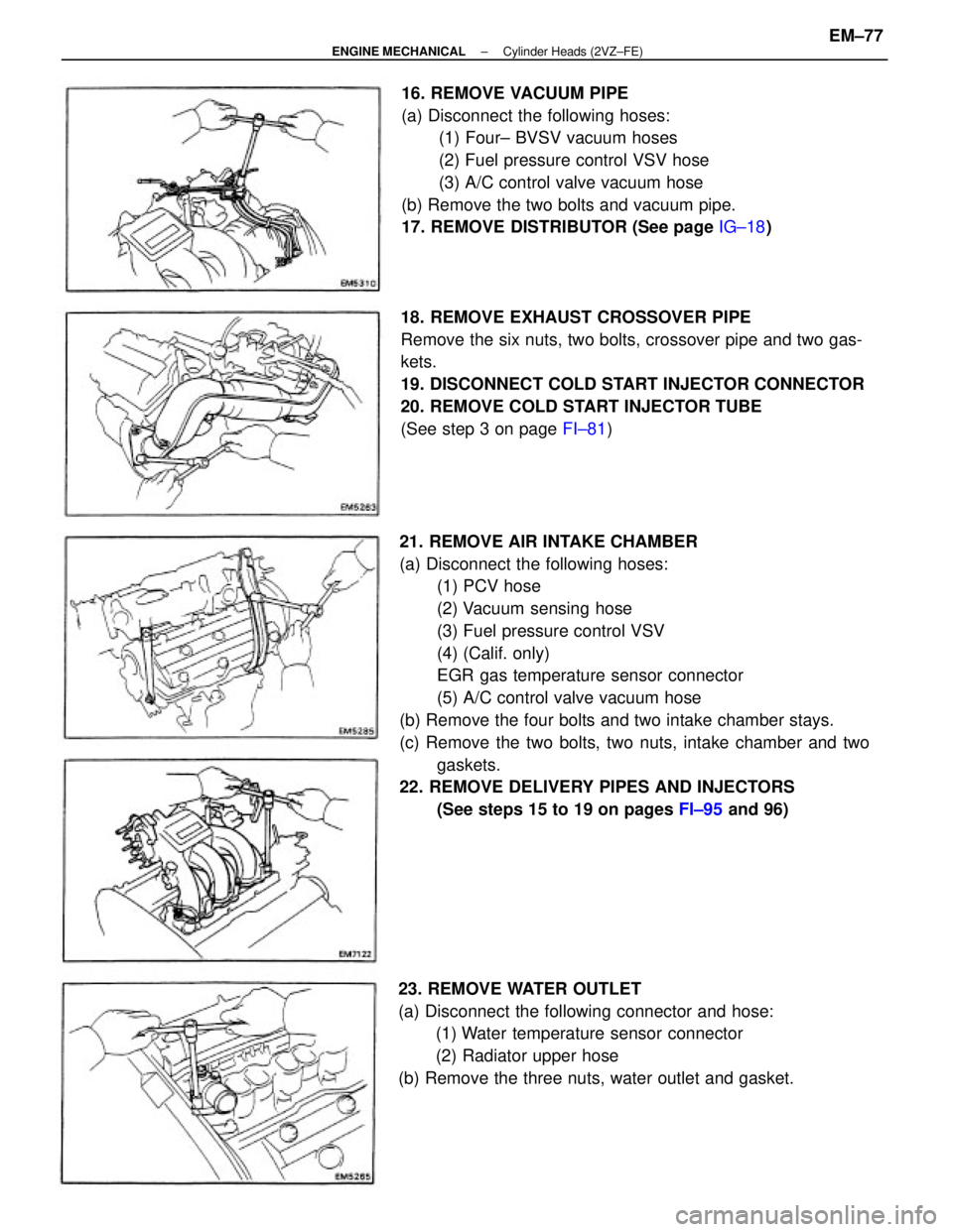
21. REMOVE AIR INTAKE CHAMBER
(a) Disconnect the following hoses:
(1) PCV hose
(2) Vacuum sensing hose
(3) Fuel pressure control VSV
(4) (Calif. only)
EGR gas temperature sensor connector
(5) A/C control valve vacuum hose
(b) Remove the four bolts and two intake chamber stays.
(c) Remove the two bolts, two nuts, intake chamber and two
gaskets.
22. REMOVE DELIVERY PIPES AND INJECTORS
(See steps 15 to 19 on pages FI±95 and 96) 18. REMOVE EXHAUST CROSSOVER PIPE
Remove the six nuts, two bolts, crossover pipe and two gas-
kets.
19. DISCONNECT COLD START INJECTOR CONNECTOR
20. REMOVE COLD START INJECTOR TUBE
(See step 3 on page FI±81) 16. REMOVE VACUUM PIPE
(a) Disconnect the following hoses:
(1) Four± BVSV vacuum hoses
(2) Fuel pressure control VSV hose
(3) A/C control valve vacuum hose
(b) Remove the two bolts and vacuum pipe.
17. REMOVE DISTRIBUTOR (See page IG±18)
23. REMOVE WATER OUTLET
(a) Disconnect the following connector and hose:
(1) Water temperature sensor connector
(2) Radiator upper hose
(b) Remove the three nuts, water outlet and gasket.
± ENGINE MECHANICALCylinder Heads (2VZ±FE)EM±77
Page 1891 of 2389
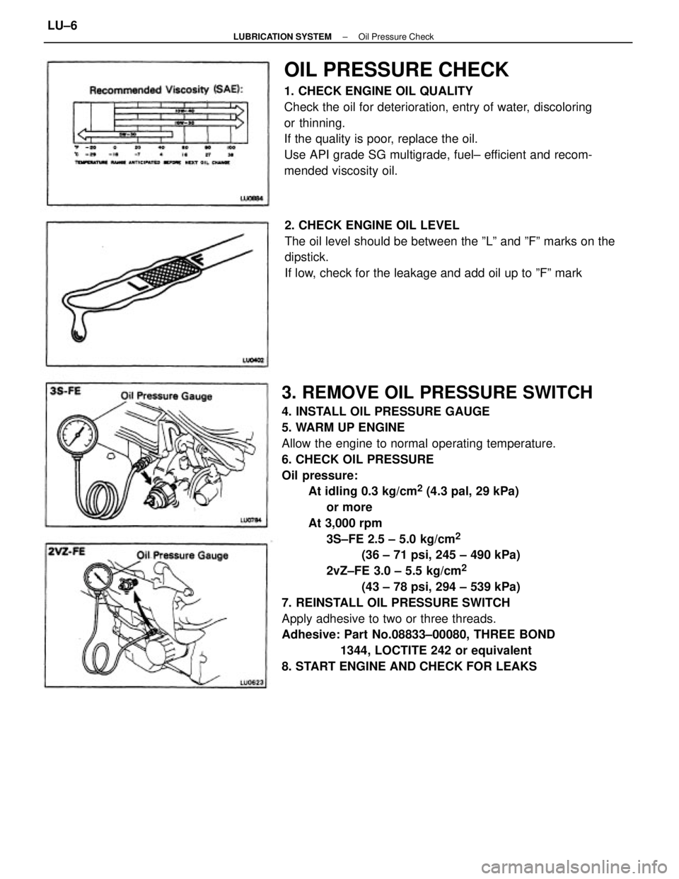
3. REMOVE OIL PRESSURE SWITCH
4. INSTALL OIL PRESSURE GAUGE
5. WARM UP ENGINE
Allow the engine to normal operating temperature.
6. CHECK OIL PRESSURE
Oil pressure:
At idling 0.3 kg/cm
2 (4.3 pal, 29 kPa)
or more
At 3,000 rpm
3S±FE 2.5 ± 5.0 kg/cm
2
(36 ± 71 psi, 245 ± 490 kPa)
2vZ±FE 3.0 ± 5.5 kg/cm
2
(43 ± 78 psi, 294 ± 539 kPa)
7. REINSTALL OIL PRESSURE SWITCH
Apply adhesive to two or three threads.
Adhesive: Part No.08833±00080, THREE BOND
1344, LOCTITE 242 or equivalent
8. START ENGINE AND CHECK FOR LEAKS
OIL PRESSURE CHECK
1. CHECK ENGINE OIL QUALITY
Check the oil for deterioration, entry of water, discoloring
or thinning.
If the quality is poor, replace the oil.
Use API grade SG multigrade, fuel± efficient and recom-
mended viscosity oil.
2. CHECK ENGINE OIL LEVEL
The oil level should be between the ºLº and ºFº marks on the
dipstick.
If low, check for the leakage and add oil up to ºFº mark
± LUBRICATION SYSTEMOil Pressure CheckLU±6
Page 1914 of 2389
GENERAL MAINTENANCE
These are the maintenance and inspection items
which are considered to be the owner's responsibility,
They can be performed by the owner or he
can have then done at a service shop. These items
include those which should be checked on a daily ba-
sis, those which, in most cases, do not require
(special) tools and those which are considered to be
reasonable for the owner to perform.
Items and procedures for general maintenance are as
follows:
OUTSIDE VEHICLE
1. TIRES
(a) Check the pressure with a gauge. Adjust
if necessary.
(b) Check for cuts, damage or excessive wear.
2. WHEEL NUTS
When checking the tires, check the nuts for looseness
or for missing nuts. If necessary,
tighten them.
3. TIRE ROTATION
It is recommended that tires be rotated every
7,500 miles (12,000 km).
4. WINDSHIELD WIPER BLADES
Check for wear or cracks whenever they do not wipe
clean. Replace if necessary.
5. FLUID LEAKS
(a) Check underneath for leaking fuel, oil, water or
other fluid.
(b) If you smell gasoline fumes or notice any leak,
have the cause found and corrected.
6. DOORS AND ENGINE HOOD
(a) Check that all doors including the trunk lid and
back door operate smoothly, and that all
latches lock securely.
(b) Check that the engine hood secondary latch se-
cures the hood from opening when the prima-
ry latch is released.
INSIDE VEHICLE
7. LIGHTS
(a) Check that the headlights, stop lights, taillights,
turn signal lights, and other
lights are all working.
(b) Check the headlight aiming.8. WARNING LIGHTS AND BUZZERS
Check that all warning lights and buzzers func-
tion properly.
9. HORN
Check that it is working.
10. WINDSHIELD GLASS
Check for scratches, pits or abrasions.
11. WINDSHIELD WIPER AND WASHER
(a) Check operation of the wipers and washer.
(b) Check that the wipers do not streak.
12. WINDSHIELD DEFROSTER
Check that air comes out from the defroster out-
let when operating the heater or air conditioner
at defroster mode.
13. REAR VIEW MIRROR
Check that it is mounted securely.
14. SUN VISORS
Check that they move freely and are mounted
securely.
15. STEERING WHEEL
Check that it has the specified freeplay. Be alert
for changes in steering condition, such as hard
steering, excessive freeplay or strange noise.
16. SEATS
(a) Check that all front seat controls such as
seat adjusters, seatback recliner, etc.
operate smoothly.
(b) Check that a11 latches lock securely in
any position.
(c) Check that the locks hold securely in any
latched position.
(d) Check that the head restraints move up
and down smoothly and that the locks
hold securely in any latched position.
(e) For folding±down rear seat backs, check
that the latches lock securely.
17. SEAT BELTS
(a) Check that the seat belt system such as
buckles, retractors and anchors operate
properly and smoothly.
(b) Check that the belt webbing is not cut,
frayed, worn or damaged.
± MAINTENANCEGeneral MaintenanceMA±16