Page 663 of 2389

38. INSTALL MANUAL VALVE BODY AND DETENT
SPRING
HINT: Each bolt length (mm (in.)) is indicated in the figure.
(a) Align the manual valve with the pin on the manual shaft le-
ver.
(b) Lower the manual valve body into place.
(e¿ Hand tighten the five bolts first. Then, tighten them
with a torque wrench.
Torque: 110 kg±cm (8 ft±Ib, 11 N±m)
(d) Place the detent springs on the manual valve body and
hand tighten the two bolts first.
Then, tighten them with a torque±wrench.
Torque: 110 kg±cm (8 ft±Ib, 11 N±m)
HINT: Each bolt length (mm (in.)) is indicated in the figure.
(e) Check that the manual valve lever is touching the center of
the detent spring tip roller.
39. INSTALL TUBE BRACKET AND OIL STRAINER
Each bolt length (mm (in.)) is indicated in the figure.
Torque:
Tube bracket 100 kg±cm (7 ft±Ib, 10 N±m)
Oil strainer 110 kg±cm (8 ft±Ib, 11 N±m))
40. INSTALL MAGNETS IN PLACE AS SHOWN
NOTICE: Make sure that the magnets do not interfere with
the oil tubes.
41. INSTALL OIL PAN WITH NEW GASKET
Torque: 50 kg±cm (43 in±Ib, 4.9 N±m)
± AUTOMATIC TRANSAXLEInstallation of Component Parts (A540E and A540H)AT±405
Page 665 of 2389
49. (A540H)
INSTALL DIFFERENTIAL SIDE GEAR INTERMEDIATE
SHAFT
(a) Install a new snap ring to the shaft groove.
(b) Using a plastic hammer, install the shaft. 48. INSTALL UNION AND ELBOW
(a) Install the new O±rings to the union and elbow.
(b) Install the union and elbow to the transaxle case.
Torque: 275 kg±cm (20 ft±Ib, 27 N±m)
HINT: Keeping the intermediate shaft on the pinion shaft of
differential, measure the point in the illustration.
Protrusion length (Reference): 255.5 mm 110.059 in.) HINT: Install the elbow at right angles to the bottom of
the transaxle case. 47. INSTALL MANUAL SHIT LEVER
± AUTOMATIC TRANSAXLEInstallation of Component Parts (A540E and A540H)AT±407
Page 666 of 2389
51. (A540H)
INSTALL TRANSFER ASSEMBLY
(a) Remove any packing material and be careful not to drop oil on
the contacting surfaces of the transfer and transaxle.
(b) Apply seal packing to the transaxle as shown in the illustration.
Seal packing: Part No. 08883±00090, Adhesive 1131,
THREE BOND 1131, Loctite 518, or equivalent
HINT: Install the transfer assembly as soon as the seal packing
is applied.
(e) Coat the threads of bolts with sealer.
Sealer: Part No. 08833±00070, THREE BOND 1324
or equivalent.
(d) Install and torque the five nuts and three bolts.
Torque: 700 kg±cm (51 ft±Ib, 69 N±m)
52. (A540H)
INSPECT MODE SELECT LEVER POSITION
After finishing inspection or repair the transaxle, be
sure the select lever position to FREE mode and at-
tach the lock bolt. 50. (A540 H )
INSTALL APPLY GASKET
Install a new apply gasket to the differential carrier cover.
± AUTOMATIC TRANSAXLEInstallation of Component Parts (A540E and A540H)AT±408
Page 711 of 2389
5. INSTALL FOLLOWING PARTS:
(a) Roof side inner garnish
(b) Rear seat belt anchor bolt
Torque: 440 kg±cm (32 ft±Ib, 43 N¿rn)
(c) Roof drip moulding
(d) (w/ Fixed Seat Type)
Rear seat
(e) (w/ Separate Seat Type)
Rear side seat back and seat cushion. 2. COAT CONTACT SURFACE OF GLASS WITH PRIMER
(a) Using a sponge, apply the primer around the entire
ceramic application area.
HINT: Apply primer evenly and to the ceramic application
area only.
(b) Let the primer coating dry for 10 minutes.
4. INSTALL QUARTER WINDOW GLASS WITH
MOULDING
(a) Fit on the moulding.
(b) Install the glass using the moulding stud bolts as a
guide.
(c) Install the four mounting nuts.
INSTALLATION OF QUARTER
WINDOW GLASS
(See page BO±43)
1. CLEAN BODY OR GLASS
Wipe oft any adhesive left on the body and glass with
cleaner.
3. APPLY SEAL TO GLASS
Install the seal to the glass.
HINT: Overlap the seal approx. 40 mm (1.57 in.) at the
front area.
± BODYQuarter Window GlassBO±45
Page 714 of 2389

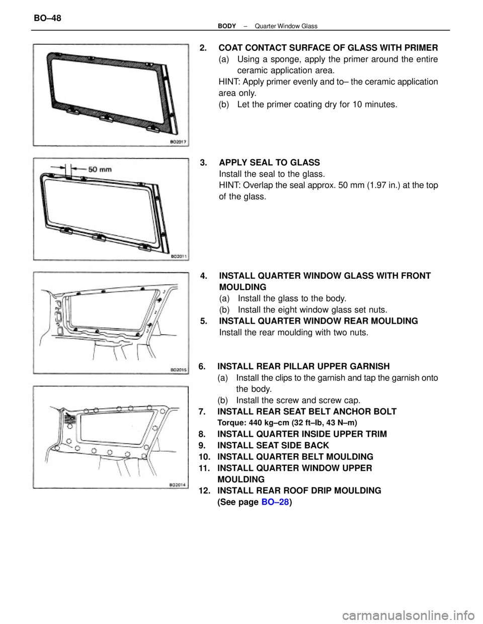
6. INSTALL REAR PILLAR UPPER GARNISH
(a) Install the clips to the garnish and tap the garnish onto
the body.
(b) Install the screw and screw cap.
7. INSTALL REAR SEAT BELT ANCHOR BOLT
Torque: 440 kg±cm (32 ft±Ib, 43 N±m)
8. INSTALL QUARTER INSIDE UPPER TRIM
9. INSTALL SEAT SIDE BACK
10. INSTALL QUARTER BELT MOULDING
11. INSTALL QUARTER WINDOW UPPER
MOULDING
12. INSTALL REAR ROOF DRIP MOULDING
(See page BO±28) 4. INSTALL QUARTER WINDOW GLASS WITH FRONT
MOULDING
(a) Install the glass to the body.
(b) Install the eight window glass set nuts.
5. INSTALL QUARTER WINDOW REAR MOULDING
Install the rear moulding with two nuts. 2. COAT CONTACT SURFACE OF GLASS WITH PRIMER
(a) Using a sponge, apply the primer around the entire
ceramic application area.
HINT: Apply primer evenly and to± the ceramic application
area only.
(b) Let the primer coating dry for 10 minutes.
3. APPLY SEAL TO GLASS
Install the seal to the glass.
HINT: Overlap the seal approx. 50 mm (1.97 in.) at the top
of the glass.
± BODYQuarter Window GlassBO±48
Page 716 of 2389

PREPARATION FOR INSTALLATION
(See pages BO±40 and 41)
INSTALLATION OF REAR WINDOW
GLASS
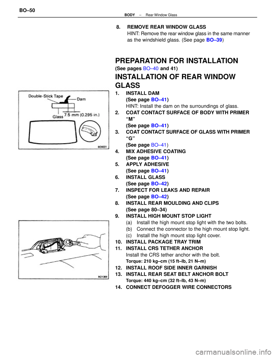
1. INSTALL DAM
(See page BO±41)
HINT: Install the dam on the surroundings of glass.
2. COAT CONTACT SURFACE OF BODY WITH PRIMER
ªMº
(See page BO±41)
3. COAT CONTACT SURFACE OF GLASS WITH PRIMER
ªGº
(See page BO±41)
4. MIX ADHESIVE COATING
(See page BO±41)
5. APPLY ADHESIVE
(See page BO±41)
6. INSTALL GLASS
(See page BO±42)
7. INSPECT FOR LEAKS AND REPAIR
(See page BO±42)
8. INSTALL REAR MOULDING AND CLIPS
(See page 80±34)
9. INSTALL HIGH MOUNT STOP LIGHT
(a) Install the high mount stop light with the two bolts.
(b) Connect the connector to the high mount stop light.
(c) Install the high mount stop light cover.
10. INSTALL PACKAGE TRAY TRIM
11. INSTALL CRS TETHER ANCHOR
Install the CRS tether anchor with the bolt.
Torque: 210 kg±cm (15 ft±Ib, 21 N±m)
12. INSTALL ROOF SIDE INNER GARNISH
13. INSTALL REAR SEAT BELT ANCHOR BOLT
Torque: 440 kg±cm (32 ft±Ib, 43 N±m)
14. CONNECT DEFOGGER WIRE CONNECTORS8. REMOVE REAR WINDOW GLASS
HINT: Remove the rear window glass in the same manner
as the windshield glass. (See page BO±39)
± BODYRear Window GlassBO±50
Page 727 of 2389
(b) (CANADA)
Install the shoulder belt anchor with the bolt.
Torque: 440 kg±cm (32 ft±Ib, 43 N±m)
7. INSTALL CENTER PILLAR LOWER GARNISH
8. INSTALL SCUFF PLATE
9. INSTALL FOLLOWING PARTS:
wFront pillar garnish
wRear view mirror
wSun visor and holder
wAssist grip
wOpening trim moulding
10. INSTALL CONTROL SWITCH
11. INSPECT AND ADJUST SLIDING ROOF
(See pages BO±54 and 55)
12. CONNECT BATTERY CABLE TO NEGATIVE
TERMINAL
REMOVAL OF SLIDING ROOF GLASS
(See page BO±53)
TO REMOVE ONLY SLIDING ROOF GLASS
(a) Slide the sunshade trim rearward.
(b) Remove the inner panel side garnish.
(e) Remove the front and rear shoe nuts.
(d) Remove the roof glass. 6. INSTALL CENTER PILLAR UPPER GARNISH
(a) Install the center pillar upper garnish¿¿ tapping.
± BODYSun RoofBO±61
Page 738 of 2389
Rear Seat
COMPONENTS
Sedan
Fixed type
: Specified torque kg±cm (ft±Ib, N±m)Separate type
185(13,18)802016
802004
802005
± BODYSeatBO±72