Page 952 of 2389
INSPECTION OF REAR SPEED SENSOR AND
SENSOR ROTOR SERRATIONS (REFERENCE)
INSPECT REAR SPEED SENSOR AND SENSOR ROTOR
SERRATIONS BY USING AN OSCILLOSCOPE
(a) Connect an oscilloscope to the speed sensor connec-
tor.
(b) Run the vehicle at 20 km/h (12.4 mph), and inspect
speed sensor output wave.
(e) Check that C is 0.5 V or more.
If not as specified, replace the speed sensor.
(d) Check that B is 60% or more of A.
If not as specified, replace the rear drive shaft. 3. VISUALLY INSPECT SENSOR ROTOR SERRATIONS
(a) Remove the drive shaft.
(See page RA±21)
(b) Inspect the sensor rotor serrations for scratches,
cracks, warping or missing teeth.
(c) Install the drive shaft.
(See page RA±26)
NOTICE: To prevent damage to the serrations, do not strike
the drive shaft.
± BRAKE SYSTEMAnti±lock Brake System (A.B.S.)BR±101
Page 954 of 2389

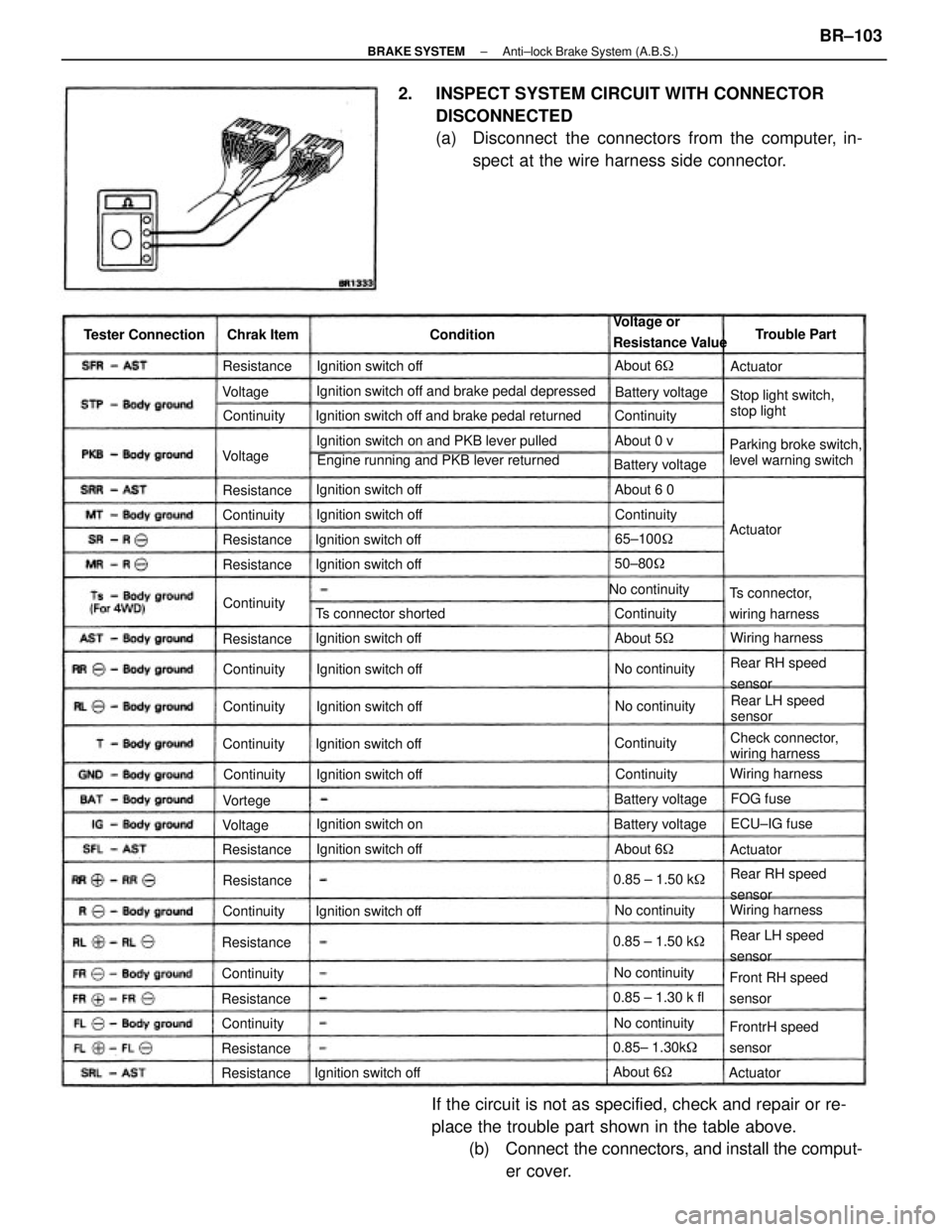
2. INSPECT SYSTEM CIRCUIT WITH CONNECTOR
DISCONNECTED
(a) Disconnect the connectors from the computer, in-
spect at the wire harness side connector.
If the circuit is not as specified, check and repair or re-
place the trouble part shown in the table above.
(b) Connect the connectors, and install the comput-
er cover.
Ignition switch off and brake pedal depressed
Engine running and PKB lever returned Ignition switch off and brake pedal returned
Ignition switch on and PKB lever pulled
Parking broke switch,
level warning switchStop light switch,
stop light Voltage or
Resistance Value
Check connector,
wiring harness
Front RH speed
sensor
FrontrH speed
sensor Ts connector,
wiring harness
Rear RH speed
sensor
Rear RH speed
sensor
Rear LH speed
sensorRear LH speed
sensor Ts connector shorted
Ignition switch offIgnition switch off
Ignition switch off
Ignition switch off Ignition switch off Tester Connection
Ignition switch offIgnition switch off
Ignition switch off
Ignition switch off Ignition switch off Ignition switch off
Ignition switch offIgnition switch off
Ignition switch onBattery voltage
No continuity
Battery voltage
0.85 ± 1.30 k fl
0.85± 1.30k� Battery voltage
Wiring harnessWiring harness
Wiring harness Battery voltage
0.85 ± 1.50 k� 0.85 ± 1.50 k�
No continuityNo continuity
No continuityNo continuityNo continuityTrouble Part
65±100�
ECU±IG fuse Chrak Item
50±80�
About 6� ContinuityResistance
Resistance
About 5� ResistanceAbout 6 0
Resistance
ResistanceAbout 6�
ResistanceContinuity Resistance
Resistance
ResistanceContinuity
ResistanceAbout 6�
ResistanceContinuity
Continuity
Continuity
ContinuityContinuity Continuity
Continuity Continuity
About 0 v
Continuity Continuity
Continuity
Continuity
FOG fuse Condition
ActuatorActuator
Actuator Voltage
VoltageVortege
Actuator Voltage
± BRAKE SYSTEMAnti±lock Brake System (A.B.S.)BR±103
Page 955 of 2389
1. REMOVE A.B.S. COMPUTER
(a) Remove the computer cover.
(b) Remove the five screws holding the computer to the
computer bracket.
(e) Pull out the wire harness from the clamp on the
bracket, and pull out the connector from the clamp
on the bracket.
(d) Disconnect the three connectors, and remove the
A.B.S. computer.
2. REMOVE DECELERATION SENSOR
Remove the two screws, and remove the deceleration
sensor.
NOTICE: Do not drive without normal installation of decel-
eration sensor and computer assembly.
REMOVAL AND INSTALLATION OF A.B.S.
COMPUTER AND DECELERATION SENSOR
(For 4WD)
± BRAKE SYSTEMAnti±lock Brake System (A.B.S.)BR±104
Page 956 of 2389
3. INSTALL DECELERATION SENSOR
(a) Install the deceleration sensor to the bracket with the
two screws.
Torque: 32.5 kg±cm (28 in.±Ib, 3.2 N±m)
(b) Install the connector to the clamp on the bracket.
(c) Check that the deceleration sensor is installed prop-
erly.
4. INSTALL A.B.S. COMPUTER
(a) Connect the three connectors and insert the wire har-
ness to the clamp.
(b) Set the computer in place, and install it with the five
screws.
Torque: 32.5 kg±cm (28 in.±Ib, 3.2 N±m)
(c) Install the computer cover.
± BRAKE SYSTEMAnti±lock Brake System (A.B.S.)BR±105
Page 1000 of 2389
(b) Check the valve opening temperature
Valve opening temperature:
80 ± 845C (176 ± 1835F)
If the valve opening temperature is not as specified, re-
place the thermostat.
(c) Check the valve lift.
Valve lift:
8.5 mm (0.335 in.) or more at 95
°C (203°F)
If the valve lift is less than specification, replace the ther-
mostat.
(d) Check that the valve spring is tight when the thermostat
is fully closed.
THERMOSTAT (2VZ±FE)
REMOVAL OF THERMOSTAT
1. DRAIN ENGINE COOLANT (See page CO±5)
2. REMOVE WATER INLET PIPE
(See steps 2 and 4 on page CO±9)
3. DISCONNECT WATER TEMPERATURE SENSOR
CONNECTOR
INSPECTION OF THERMOSTAT
INSPECT THERMOSTAT
HINT: The thermostat is numbered with the valve opening
temperature.
(a) Immerse the thermostat in water and gradually heat the wa-
ter. 4. REMOVE WATER INLET
Remove the three nuts and water inlet from the water
pump.
5. REMOVE THERMOSTAT AND GASKET
± COOLING SYSTEMThermostat (2VZ±FE)CO±13
Page 1001 of 2389
INSTALLATION OF THERMOSTAT
1. PLACE THERMOSTAT IN WATER PUMP
(a) install a new gasket to the thermostat.
(b) Align the jiggle valve of the thermostat with stud bolt
(A), and insert the thermostat in the water pump.
3. CONNECT WATER TEMPERATURE SENSOR
CONNECTOR
4. INSTALL WATER INLET PIPE
(See steps 3 and 5 on page CO±11)
5. FILL WITH ENGINE COOLANT (See page CO±5)
6. START ENGINE AND CHECK FOR LEAKS2. INSTALL WATER INLET
Install the water inlet with the three nuts.
Torque: 200 kg±cm (14 ft±Ib, 20 N±m)
± COOLING SYSTEMThermostat (2VZ±FE)CO±14
Page 1011 of 2389

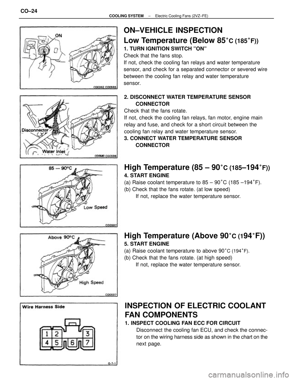
ON±VEHICLE INSPECTION
Low Temperature (Below 85
°C (185°F))
1. TURN IGNITION SWITCH ºONº
Check that the fans stop.
If not, check the cooling fan relays and water temperature
sensor, and check for a separated connector or severed wire
between the cooling fan relay and water temperature
sensor.
2. DISCONNECT WATER TEMPERATURE SENSOR
CONNECTOR
Check that the fans rotate.
If not, check the cooling fan relays, fan motor, engine main
relay and fuse, and check for a short circuit between the
cooling fan relay and water temperature sensor.
3. CONNECT WATER TEMPERATURE SENSOR
CONNECTOR
INSPECTION OF ELECTRIC COOLANT
FAN COMPONENTS
1. INSPECT COOLING FAN ECC FOR CIRCUIT
Disconnect the cooling fan ECU, and check the connec-
tor on the wiring harness side as shown in the chart on the
next page.
High Temperature (85 ± 90°C (185±194°F))
4. START ENGINE
(a) Raise coolant temperature to 85 ± 90°C (185 ±194°F).
(b) Check that the fans rotate. (at low speed)
If not, replace the water temperature sensor.
High Temperature (Above 90°C (194°F))
5. START ENGINE
(a) Raise coolant temperature to above 90
°C (194°F).
(b) Check that the fans rotate. (at high speed)
If not, replace the water temperature sensor.
± COOLING SYSTEMElectric Cooling Fans (2VZ±FE)CO±24
Page 1012 of 2389
5. INSPECT NO±2 COOLING FAN RELAY
(ºAC FAN NO.2º)
A. Inspect relay continuity
(a) Using an ohmmeter, check that there is continuity between
terminals 2 and 6.
(b) Check that there is continuity between terminals 1 and 3.
(c) Check that there is no continuity between terminals 1
and 4.
If continuity is not as specified, replace the relay. 2. INSPECT WATER TEMPERATURE SENSOR
Using an ohmmeter, measure the resistance between the
terminals.
Resistance:
Approx. 1.53 k� at 80°C (176° F)
Approx. 1.18 k� at 90°C (194° F)
Approx. 1.03 k� at 95°C (203°F)
If resistance is not as specified, replace the sensor.
3. INSPECT ENGINE MAIN RELAY (See page CH±16)
4. INSPECT NO.1 COOLING FAN RELAY (ºFAN NO.1 º)
(See page CO±22)
Ignition switch ON Ignition switch ON Tester connectionSpecified valve Condition
Battery voltageBattery voltage
Coolant temp.
Continuity
ContinuityContinuity ResistanceContinuity Check for
Voltage
Voltage
± COOLING SYSTEMElectric Cooling Fans (2VZ±FE)CO±25