1986 TOYOTA CAMRY V20 sensor
[x] Cancel search: sensorPage 1033 of 2389
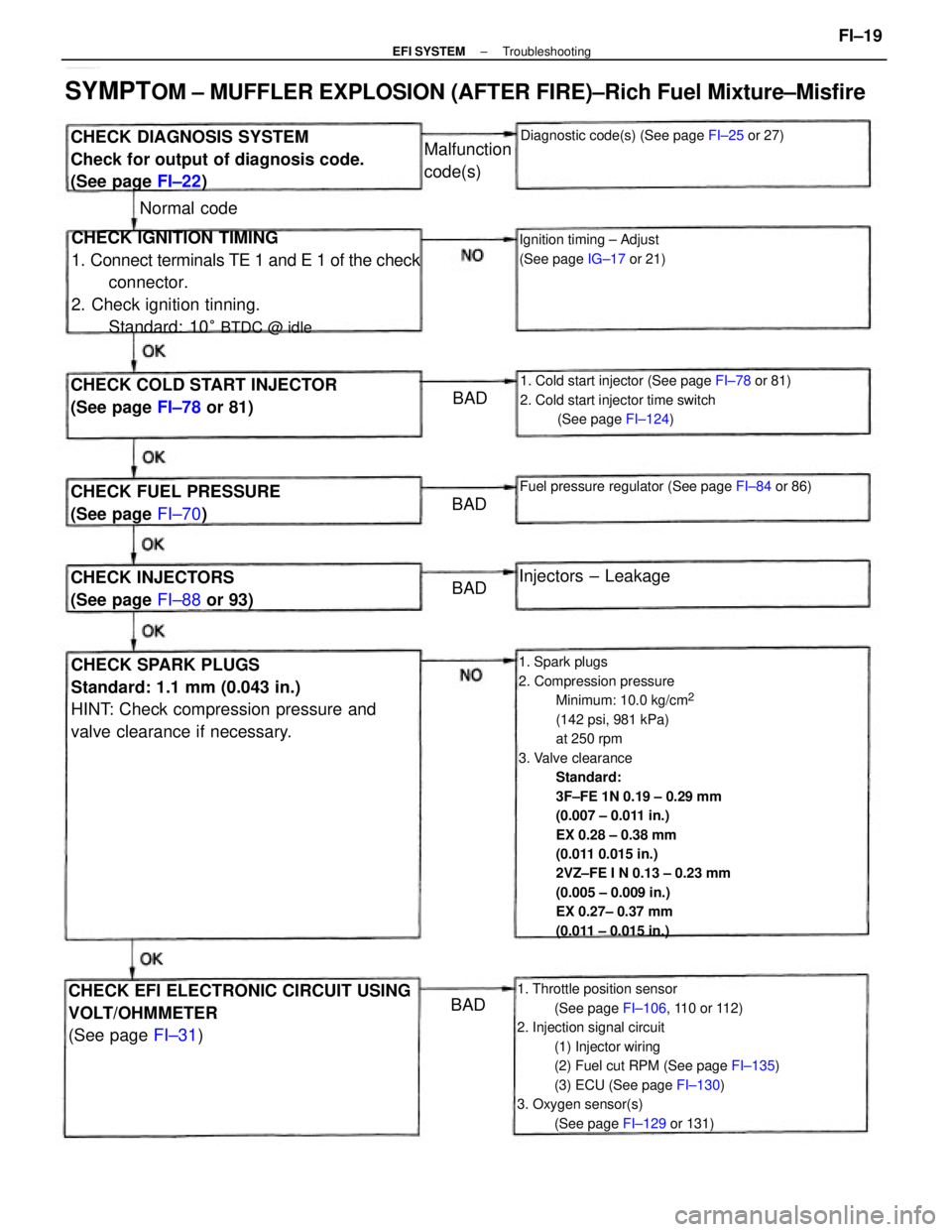
1. Spark plugs
2. Compression pressure
Minimum: 10.0 kg/cm
2
(142 psi, 981 kPa)
at 250 rpm
3. Valve clearance
Standard:
3F±FE 1N 0.19 ± 0.29 mm
(0.007 ± 0.011 in.)
EX 0.28 ± 0.38 mm
(0.011 0.015 in.)
2VZ±FE I N 0.13 ± 0.23 mm
(0.005 ± 0.009 in.)
EX 0.27± 0.37 mm
(0.011 ± 0.015 in.)
1. Throttle position sensor
(See page FI±106, 110 or 112)
2. Injection signal circuit
(1) Injector wiring
(2) Fuel cut RPM (See page FI±135)
(3) ECU (See page FI±130)
3. Oxygen sensor(s)
(See page FI±129 or 131)
CHECK IGNITION TIMING
1. Connect terminals TE 1 and E 1 of the check
connector.
2. Check ignition tinning.
Standard: 10
° BTDC @ idle
CHECK SPARK PLUGS
Standard: 1.1 mm (0.043 in.)
HINT: Check compression pressure and
valve clearance if necessary.
SYMPTOM ± MUFFLER EXPLOSION (AFTER FIRE)±Rich Fuel Mixture±Misfire
CHECK EFI ELECTRONIC CIRCUIT USING
VOLT/OHMMETER
(See page FI±31)
1. Cold start injector (See page FI±78 or 81)
2. Cold start injector time switch
(See page FI±124)
CHECK DIAGNOSIS SYSTEM
Check for output of diagnosis code.
(See page FI±22)
CHECK COLD START INJECTOR
(See page FI±78 or 81)
Fuel pressure regulator (See page FI±84 or 86)CHECK FUEL PRESSURE
(See page FI±70)
Diagnostic code(s) (See page FI±25 or 27)
Ignition timing ± Adjust
(See page IG±17 or 21)
CHECK INJECTORS
(See page FI±88 or 93)Injectors ± Leakage Malfunction
code(s)
Normal code
BAD
BAD
BADBAD
± EFI SYSTEMTroubleshootingFI±19
Page 1035 of 2389
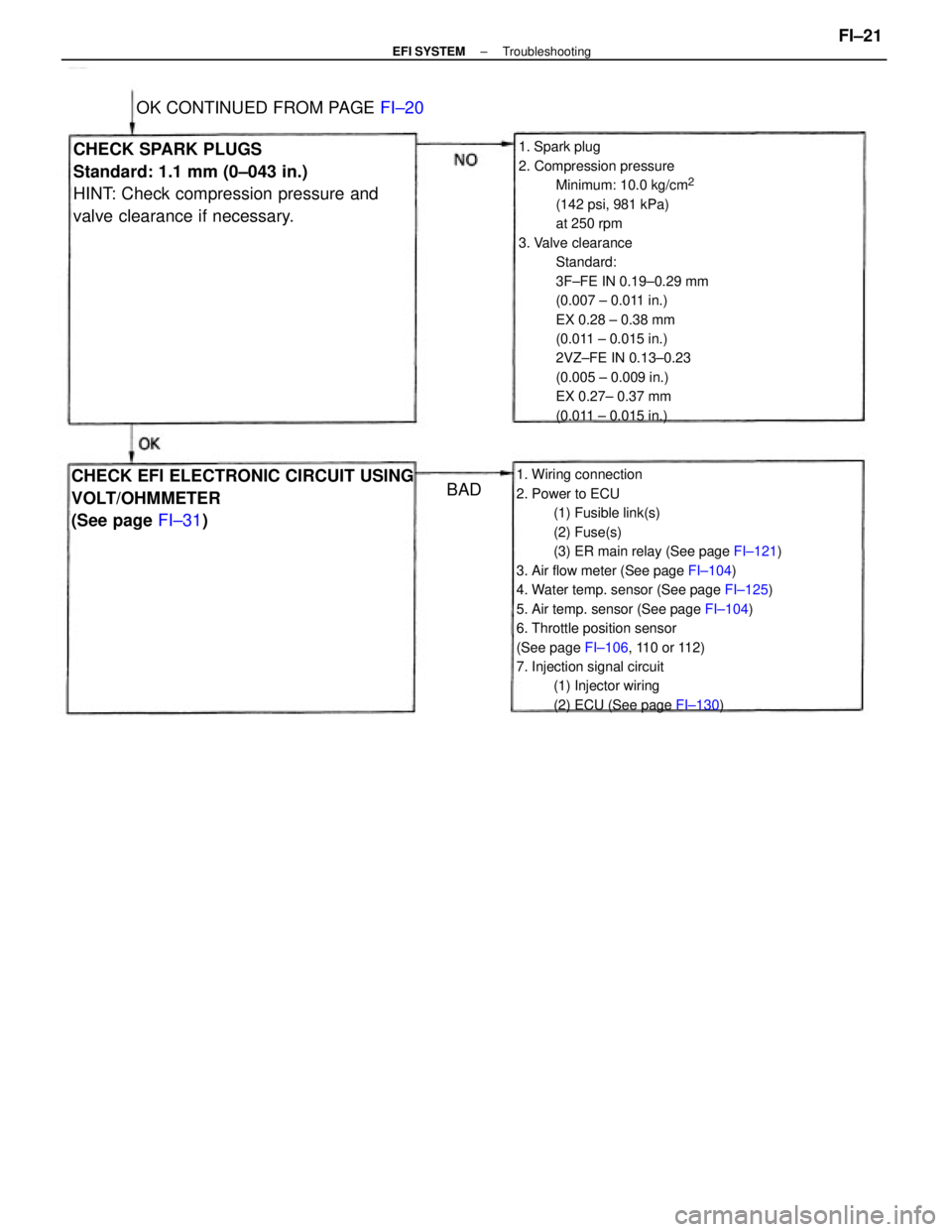
1. Spark plug
2. Compression pressure
Minimum: 10.0 kg/cm
2
(142 psi, 981 kPa)
at 250 rpm
3. Valve clearance
Standard:
3F±FE IN 0.19±0.29 mm
(0.007 ± 0.011 in.)
EX 0.28 ± 0.38 mm
(0.011 ± 0.015 in.)
2VZ±FE IN 0.13±0.23
(0.005 ± 0.009 in.)
EX 0.27± 0.37 mm
(0.011 ± 0.015 in.)
1. Wiring connection
2. Power to ECU
(1) Fusible link(s)
(2) Fuse(s)
(3) ER main relay (See page FI±121)
3. Air flow meter (See page FI±104)
4. Water temp. sensor (See page FI±125)
5. Air temp. sensor (See page FI±104)
6. Throttle position sensor
(See page FI±106, 110 or 112)
7. Injection signal circuit
(1) Injector wiring
(2) ECU (See page FI±130)
CHECK SPARK PLUGS
Standard: 1.1 mm (0±043 in.)
HINT: Check compression pressure and
valve clearance if necessary.
CHECK EFI ELECTRONIC CIRCUIT USING
VOLT/OHMMETER
(See page FI±31) OK CONTINUED FROM PAGE FI±20
BAD
± EFI SYSTEMTroubleshootingFI±21
Page 1036 of 2389
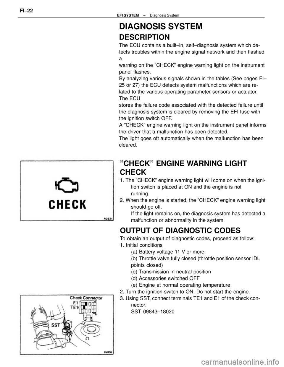
DIAGNOSIS SYSTEM
DESCRIPTION
The ECU contains a built±in, self±diagnosis system which de-
tects troubles within the engine signal network and then flashed
a
warning on the ºCHECKº engine warning light on the instrument
panel flashes.
By analyzing various signals shown in the tables (See pages FI±
25 or 27) the ECU detects system malfunctions which are re-
lated to the various operating parameter sensors or actuator.
The ECU
stores the failure code associated with the detected failure until
the diagnosis system is cleared by removing the EFI fuse with
the ignition switch OFF.
A ºCHECKº engine warning light on the instrument panel informs
the driver that a malfunction has been detected.
The light goes oft automatically when the malfunction has been
cleared.
OUTPUT OF DIAGNOSTIC CODES
To obtain an output of diagnostic codes, proceed as follow:
1. Initial conditions
(a) Battery voltage 11 V or more
(b) Throttle valve fully closed (throttle position sensor IDL
points closed)
(e) Transmission in neutral position
(d) Accessories switched OFF
(e) Engine at normal operating temperature
2. Turn the ignition switch to ON. Do not start the engine.
3. Using SST, connect terminals TE1 and E1 of the check con-
nector.
SST 09843±18020
ºCHECKº ENGINE WARNING LIGHT
CHECK
1. The ºCHECKº engine warning light will come on when the igni-
tion switch is placed at ON and the engine is not
running.
2. When the engine is started, the ºCHECKº engine warning light
should go off.
If the light remains on, the diagnosis system has detected a
malfunction or abnormality in the system.
± EFI SYSTEMDiagnosis SystemFI±22
Page 1039 of 2389
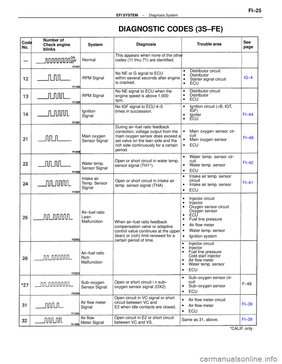
wInjector circuit
wInjector
wOxygen sensor circuit
Oxygen sensor
wECU
wFuel line pressure
wAir flow meter
wWater temp. sensor
wIgnition system During air±fuel ratio feedback
correction, voltage output from the
main oxygen sensor does exceed a
set valve on the lean side and the
rich side continuously for a certain
period.
When air±fuel ratio feedback
compensation valve or adaptive
control value continues at the upper
(lean) or (rich) limit renewed for a
certain period of time.
wInjector circuit
wInjector
wFuel line pressure
Cold start injector
wAir flow meter
wWater temp. sensor
wECU
Open circuit in VC signal or short
circuit between VC and
E2 when idle contacts are closed.wIgnition circuit (+B, IGT,
IGF)
wIgniter
wECU
Open or short circuit i n sub±
oxygen sensor signal (OX2)wIntake air temp. sensor
circuit
wIntake air temp. sensor
wECU No NE signal to ECU when the
engine speed is above 1,000
rpm. This appears when none of the other
codes (11 thru 71) are identified.
No NE or G signal to ECU
within several seconds after engine
is cracked.
wMain oxygen sensor cir-
cuit
wMain oxygen sensor
wECU wDistributor circuit
wDistributor
wStarter signal circuit
wECU
wWater temp. sensor cir-
cuit
wWater temp. sensor
wECU
wSub±oxygen sensor cir-
cuit
wSub±oxygen sensor
wECU
DIAGNOSTIC CODES (3S±FE)
wAir flow meter circuit
wAir flow meter
wECU Open or short circuit in water temp.
sensor signal (TH1^).
Open or short circuit in intake air
temp. sensor signal (THA)
Open circuit in E2 or short circuit
between VC and VS.No IGF signal to ECU 4±5
times in succession.wDistributor circuit
wDistributor
wECU
Intake air
Temp. Sensor
Signal Number of
Check engine
blinks
Air±fuel ratio
Lean
Malfunction
Air±fuel ratio
Rich
MalfunctionMain oxygen
Sensor Signal
Water temp.
Sensor Signal
Sub±oxygen
Sensor Signal
Air flow
Meter SignalAir flow meter
Signal
Same as 31, above.
*CALIF. only Ignition
SignalRPM Signal
RPM SignalTrouble area
DiagnosisSee
page System Code
No.
Normal
FI±42
FI±39FI±48
FI±39F±48FI±41IG±4
FI±44
± EFI SYSTEMDiagnosis SystemFI±25
Page 1040 of 2389
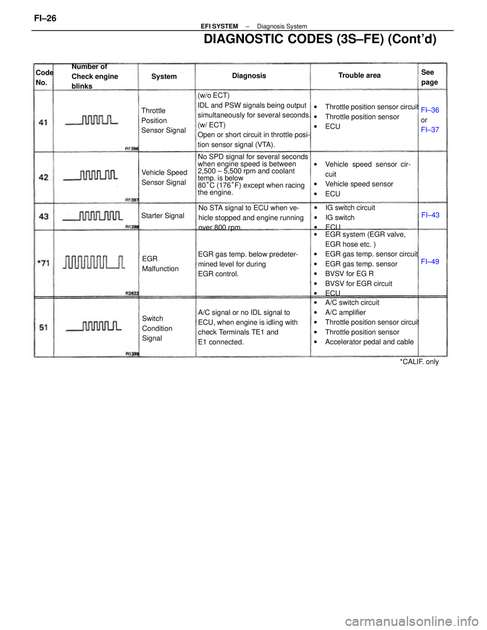
(w/o ECT)
IDL and PSW signals being output
simultaneously for several seconds.
(w/ ECT)
Open or short circuit in throttle posi-
tion sensor signal (VTA).
wEGR system (EGR valve,
EGR hose etc. )
wEGR gas temp. sensor circuit
wEGR gas temp. sensor
wBVSV for EG R
wBVSV for EGR circuit
wECU
wA/C switch circuit
wA/C amplifier
wThrottle position sensor circuit
wThrottle position sensor
wAccelerator pedal and cable No SPD signal for several seconds
when engine speed is between
2,500 ± 5,500 rpm and coolant
temp. is below
80°C (176°F) except when racing
the engine.
DIAGNOSTIC CODES (3S±FE) (Cont'd)
A/C signal or no IDL signal to
ECU, when engine is idling with
check Terminals TE1 and
E1 connected.wThrottle position sensor circuit
wThrottle position sensor
wECU
wVehicle speed sensor cir-
cuit
wVehicle speed sensor
wECU
EGR gas temp. below predeter-
mined level for during
EGR control.No STA signal to ECU when ve-
hicle stopped and engine running
over 800 rpm.wIG switch circuit
wIG switch
wECU Number of
Check engine
blinks
Throttle
Position
Sensor Signal
Switch
Condition
Signal Vehicle Speed
Sensor Signal
EGR
Malfunction Starter Signal
*CALIF. only Trouble area
FI±36
or
FI±37 DiagnosisSee
page Code
No.System
FI±49FI±43
± EFI SYSTEMDiagnosis SystemFI±26
Page 1041 of 2389
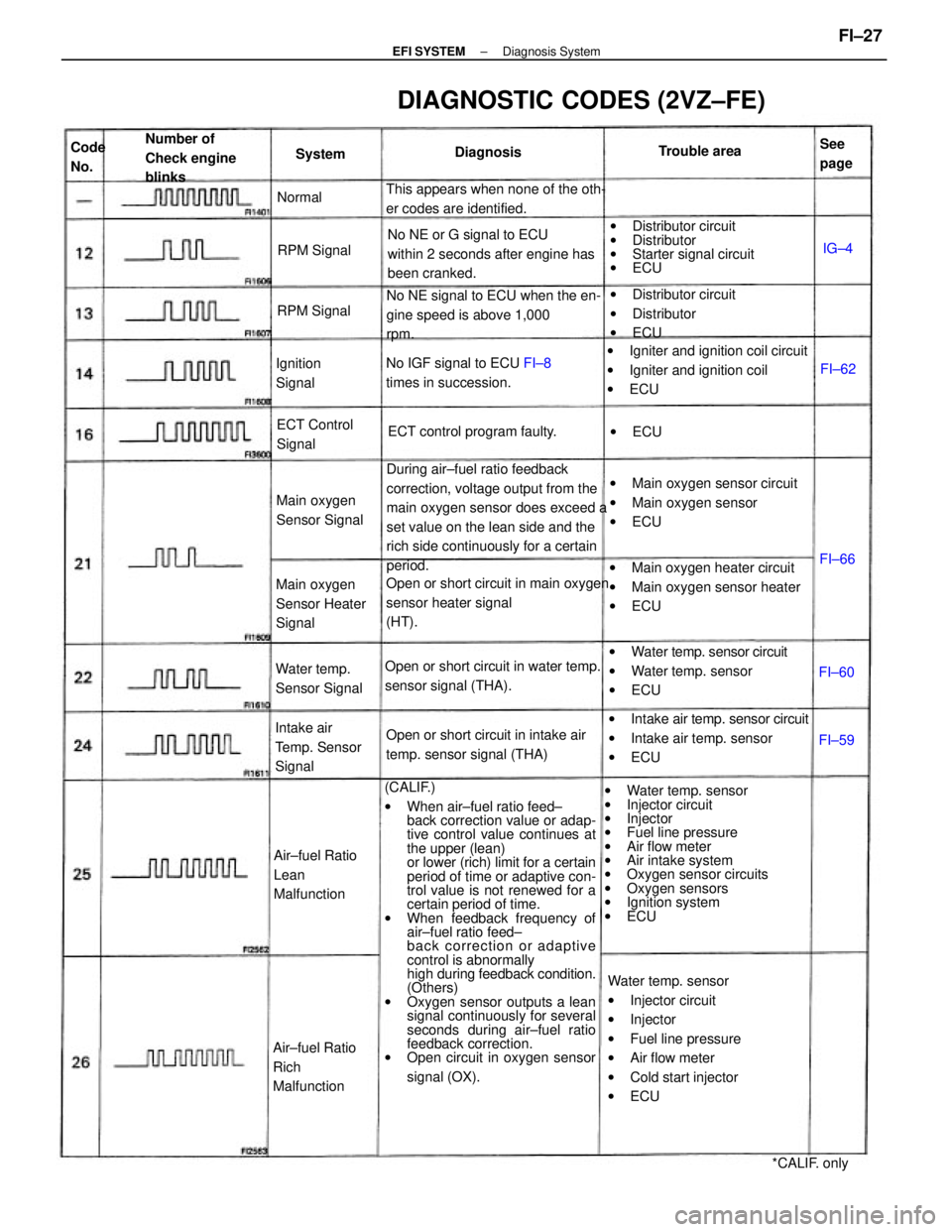
(CALIF.)
wWhen air±fuel ratio feed±
back correction value or adap-
tive control value continues at
the upper (lean)
or lower (rich) limit for a certain
period of time or adaptive con-
trol value is not renewed for a
certain period of time.
wWhen feedback frequency of
air±fuel ratio feed±
back correction or adaptive
control is abnormally
high during feedback condition.
(Others)
wOxygen sensor outputs a lean
signal continuously for several
seconds during air±fuel ratio
feedback correction.
wOpen circuit in oxygen sensor
signal (OX).wWater temp. sensor
wInjector circuit
wInjector
wFuel line pressure
wAir flow meter
wAir intake system
wOxygen sensor circuits
wOxygen sensors
wIgnition system
wECU During air±fuel ratio feedback
correction, voltage output from the
main oxygen sensor does exceed a
set value on the lean side and the
rich side continuously for a certain
period.
Water temp. sensor
wInjector circuit
wInjector
wFuel line pressure
wAir flow meter
wCold start injector
wECU wMain oxygen heater circuit
wMain oxygen sensor heater
wECU wIgniter and ignition coil circuit
wIgniter and ignition coil
wECU
wIntake air temp. sensor circuit
wIntake air temp. sensor
wECU Open or short circuit in main oxygen
sensor heater signal
(HT).No NE signal to ECU when the en-
gine speed is above 1,000
rpm.wDistributor circuit
wDistributor
wStarter signal circuit
wECU
wMain oxygen sensor circuit
wMain oxygen sensor
wECU No NE or G signal to ECU
within 2 seconds after engine has
been cranked.
wWater temp. sensor circuit
wWater temp. sensor
wECU
DIAGNOSTIC CODES (2VZ±FE)
Open or short circuit in water temp.
sensor signal (THA).
Open or short circuit in intake air
temp. sensor signal (THA) This appears when none of the oth-
er codes are identified.
wDistributor circuit
wDistributor
wECU
No IGF signal to ECU FI±8
times in succession.
Intake air
Temp. Sensor
Signal
Air±fuel Ratio
Lean
Malfunction Number of
Check engine
blinks
Air±fuel Ratio
Rich
MalfunctionMain oxygen
Sensor Heater
SignalECT control program faulty.
Main oxygen
Sensor Signal
Water temp.
Sensor SignalECT Control
Signal
*CALIF. only Ignition
SignalTrouble area
RPM Signal
RPM SignalDiagnosisSee
page Code
No.System
Normal
wECU
FI±60FI±66
FI±59FI±62IG±4
± EFI SYSTEMDiagnosis SystemFI±27
Page 1042 of 2389
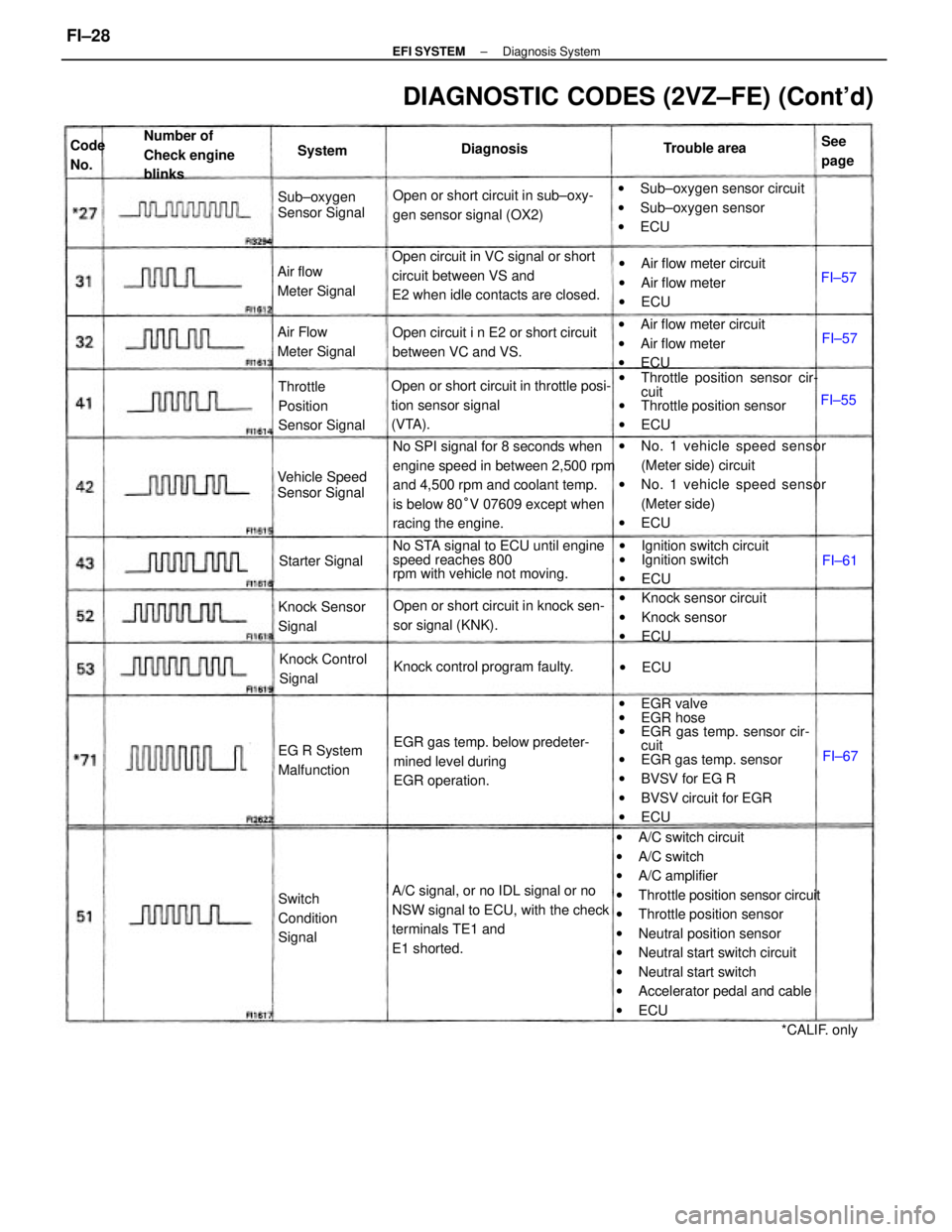
wA/C switch circuit
wA/C switch
wA/C amplifier
wThrottle position sensor circuit
wThrottle position sensor
wNeutral position sensor
wNeutral start switch circuit
wNeutral start switch
wAccelerator pedal and cable
wECU wEGR valve
wEGR hose
wEGR gas temp. sensor cir-
cuit
wEGR gas temp. sensor
wBVSV for EG R
wBVSV circuit for EGR
wECU No SPI signal for 8 seconds when
engine speed in between 2,500 rpm
and 4,500 rpm and coolant temp.
is below 80°V 07609 except when
racing the engine.wNo. 1 vehicle speed sensor
(Meter side) circuit
wNo. 1 vehicle speed sensor
(Meter side)
wECU
A/C signal, or no IDL signal or no
NSW signal to ECU, with the check
terminals TE1 and
E1 shorted. Open circuit in VC signal or short
circuit between VS and
E2 when idle contacts are closed.
wThrottle position sensor cir-
cuit
wThrottle position sensor
wECU
DIAGNOSTIC CODES (2VZ±FE) (Cont'd)
Open or short circuit in throttle posi-
tion sensor signal
(VTA).
No STA signal to ECU until engine
speed reaches 800
rpm with vehicle not moving.
EGR gas temp. below predeter-
mined level during
EGR operation.wSub±oxygen sensor circuit
wSub±oxygen sensor
wECU Open or short circuit in sub±oxy-
gen sensor signal (OX2)
wIgnition switch circuit
wIgnition switch
wECU wAir flow meter circuit
wAir flow meter
wECU wAir flow meter circuit
wAir flow meter
wECU
Open or short circuit in knock sen-
sor signal (KNK).wKnock sensor circuit
wKnock sensor
wECU Open circuit i n E2 or short circuit
between VC and VS.
Knock control program faulty. Throttle
Position
Sensor Signal Number of
Check engine
blinks
Knock Sensor
Signal
Switch
Condition
SignalKnock Control
Signal Air Flow
Meter Signal
Vehicle Speed
Sensor Signal Air flow
Meter SignalSub±oxygen
Sensor Signal
EG R System
MalfunctionStarter Signal
*CALIF. only Trouble area
DiagnosisSee
page System Code
No.
wECUFI±55FI±57
FI±57
FI±67 FI±61
± EFI SYSTEMDiagnosis SystemFI±28
Page 1056 of 2389
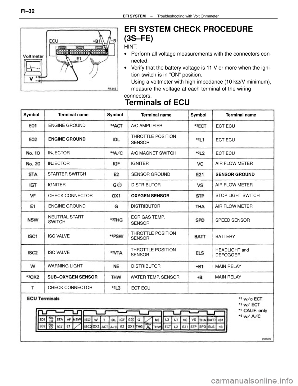
EFI SYSTEM CHECK PROCEDURE
(3S±FE)
HINT:
wPerform all voltage measurements with the connectors con-
nected.
wVerify that the battery voltage is 11 V or more when the igni-
tion switch is in ºONº position.
Using a voltmeter with high impedance (10 kW/V minimum),
measure the voltage at each terminal of the wiring
connectors.
THROTTLE POSITION
SENSORTHROTTLE POSITION
SENSOR
THROTTLE POSITION
SENSOR
Terminals of ECU
NEUTRAL START
SWITCH
HEADLIGHT and
DEFOGGER EGR GAS TEMP.
SENSOR
WATER TEMP. SENSOR SUB±OXYGEN SENSORA/C MAGNET SWITCH
STOP LIGHT SWITCH
CHECK CONNECTORCHECK CONNECTORAIR FLOW METER
AIR FLOW METER
AIR FLOW METER STARTER SWITCH
SENSOR GROUND SENSOR GROUND ENGINE GROUND
ENGINE GROUND ENGINE GROUND
OXYGEN SENSOR
WARNING LIGHTA/C AMPLIFIER
SPEED SENSORTerminal name Terminal name Terminal name
DISTRIBUTORDISTRIBUTOR
DISTRIBUTOR
MAIN RELAYMAIN RELAY ISC VALVE
ISC VALVE INJECTORINJECTOR Symbol
BATTERY Symbol
Symbol
IGNITERECT ECUECT ECU
ECT ECU
IGNITER
ECT ECU
± EFI SYSTEMTroubleshooting with Volt OhmmeterFI±32