Page 671 of 2389
3. REMOVE REAR VIEW MIRROR
(a) (Manual type)
Remove the setting screw and knob.
(b) Using a screwdriver, pry loose the retainer and re-
move the cover.
HINT: Tape the screwdriver tip before use.
(c) (Electrical type)
Disconnect the connector.
(d) Remove the three screws±and mirror.
(c) Insert a screwdriver between the retainers and door
trim to pry it loose.
HINT: Tape the screwdriver tip before use.
(d) (w/ Power Window and Power Door Lock)
Disconnect the connectors.
5. REMOVE SERVICE HOLE COVER
6. REMOVE OPENING CONTROL LINK FROM DOOR
LOCK
DISASSEMBLY OF FRONT DOOR
1. REMOVE REGULATOR HANDLE
(w/o POWER WINDOW)
Pull oft the snap ring with a cloth and remove the regulator
handle and plate.
2. REMOVE DOOR INSIDE HANDLE
(a) Remove the screw, and slide the handle forward.
(b) Disconnect the handle from the control link and re-
move the handle.
4. REMOVE DOOR TRIM
(a) Remove the two screws from the armrest.
(b) Remove the two caps and two screws.
± BODYFront DoorBO±5
Page 675 of 2389
(b) With the door glass fully closed, .adjust the door glass
stopper so it lightly makes contact with the glass
plate.
11. INSTALL OPENING CONTROL LINK
12. INSTALL SERVICE HOLE COVER
13. INSTALL DOOR TRIM8. INSTALL DOOR GLASS
(a) Place the glass in the door cavity.
(b) Install the glass to the regulator with the two mount-
ing nuts.
9. INSTALL DOOR GLASS RUN
14. INSTALL REAR VIEW MIRROR
(a) Install the mirror with the three screws.
(b) (Electrical type)
Connect the connector.
(c) Install the cover.
(d) (Manual type)
Install the knob with the setting screw.
15. INSTALL DOOR INSIDE HANDLE
(a) Connect the handle to the control link.
(b) Install the handle, slide it rearward, and install the
screw. 10. ADJUST DOOR GLASS
(a) Adjust the equalizer arm up or down and tighten it
where dimensions A and6, as shown, are equal.
± BODYFront DoorBO±9
Page 704 of 2389
2. REMOVE FOLLOWING PARTS:
(a) Inner rear view mirror
(b) Sun visors and holders
(e) Hood
(d) Wiper arms
3. REMOVE WINDSHIELD MOULDING
(See pages BO±25 and 26)
REMOVAL OF WINDSHIELD
1. REMOVE FRONT PILLAR GARNISH
(a) Pry out the clips by your hand.
(b) Pull the garnish upward to remove it.
COMPONENTS
± BODYWindshieldBO±38
Page 708 of 2389

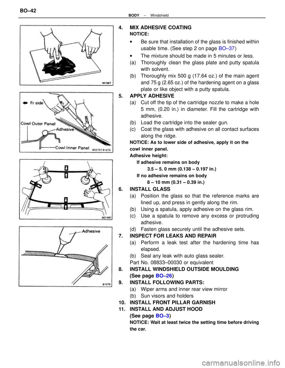
4. MIX ADHESIVE COATING
NOTICE:
wBe sure that installation of the glass is finished within
usable time. (See step 2 on page BO±37)
wThe mixture should be made in 5 minutes or less.
(a) Thoroughly clean the glass plate and putty spatula
with solvent.
(b) Thoroughly mix 500 g (17.64 oz.) of the main agent
and 75 g (2.65 oz.) of the hardening agent on a glass
plate or like object with a putty spatula.
5. APPLY ADHESIVE
(a) Cut off the tip of the cartridge nozzle to make a hole
5 mm, (0.20 in.) in diameter. Fill the cartridge with
adhesive.
(b) Load the cartridge into the sealer gun.
(c) Coat the glass with adhesive on all contact surfaces
along the ridge.
NOTICE: As to lower side of adhesive, apply it on the
cowl inner panel.
Adhesive height:
If adhesive remains on body
3.5 ± 5. 0 mm (0.138 ± 0.197 in.)
If no adhesive remains on body
8 ± 10 mm (0.31 ± 0.39 in.)
6. INSTALL GLASS
(a) Position the glass so that the reference marks are
lined up, and press in gently along the rim.
(b) Using a spatula, apply adhesive on the glass rim.
(c) Use a spatula to remove any excess or protruding
adhesive.
(d) Fasten glass securely until the adhesive sets.
7. INSPECT FOR LEAKS AND REPAIR
(a) Perform a leak test after the hardening time has
elapsed.
(b) Seal any leak with auto glass sealer.
Part No. 08833±00030 or equivalent
8. INSTALL WINDSHIELD OUTSIDE MOULDING
(See page BO±26)
9. INSTALL FOLLOWING PARTS:
(a) Wiper arms and inner rear view mirror
(b) Sun visors and holders
10. INSTALL FRONT PILLAR GARNISH
11. INSTALL AND ADJUST HOOD
(See page BO±3)
NOTICE: Wait at least twice the setting time before driving
the car.
± BODYWindshieldBO±42
Page 722 of 2389
REMOVAL OF SUN ROOF
(See page BO±53)
1. DISCONNECT BATTERY CABLE FROM NEGATIVE
TERMINAL
2. REMOVE CONTROL SWITCH
3. REMOVE FOLLOWING PARTS:
wFront pillar garnishr Assist grip
wRear view mirror
wSun visor and holder
wOpening trim moulding
4. REMOVE CENTER PILLAR LOWER GARNISH
(a) Remove the front and rear door opening trims.
(b) Remove the front and rear scuff plates.
(e) Pry out the clips and remove the center pillar lower
garnish.
6. REMOVE FRONT SIDE ROOF HEADLINING
Tear off the roof headlining portion stuck with double±stick
tape between front all center pillar. 5. REMOVE CENTER PILLAR UPPER GARNISH
(a) (CANADA)
Remove the front shoulder belt anchor.
(b) Using a screwdriver, pry out the clips.
HINT: Tape the screwdriver tip before use.
(c) Remove the center pillar upper garnish.
± BODYSun RoofBO±56
Page 727 of 2389
(b) (CANADA)
Install the shoulder belt anchor with the bolt.
Torque: 440 kg±cm (32 ft±Ib, 43 N±m)
7. INSTALL CENTER PILLAR LOWER GARNISH
8. INSTALL SCUFF PLATE
9. INSTALL FOLLOWING PARTS:
wFront pillar garnish
wRear view mirror
wSun visor and holder
wAssist grip
wOpening trim moulding
10. INSTALL CONTROL SWITCH
11. INSPECT AND ADJUST SLIDING ROOF
(See pages BO±54 and 55)
12. CONNECT BATTERY CABLE TO NEGATIVE
TERMINAL
REMOVAL OF SLIDING ROOF GLASS
(See page BO±53)
TO REMOVE ONLY SLIDING ROOF GLASS
(a) Slide the sunshade trim rearward.
(b) Remove the inner panel side garnish.
(e) Remove the front and rear shoe nuts.
(d) Remove the roof glass. 6. INSTALL CENTER PILLAR UPPER GARNISH
(a) Install the center pillar upper garnish¿¿ tapping.
± BODYSun RoofBO±61
Page 809 of 2389
Remote Control Mirror
INSPECTION OF MIRROR
INSPECT MIRROR OPERATION
(a) Connect the positive (+) lead from the battery to ter-
minal 1 and negative lead to terminal 2, check that
the mirror moves upward.
Then, reverse the polarity, check that the mirror
operation is reversed.
(b) Connect the positive (+) lead from the battery to ter-
minal 2 and negative(±) lead to terminal 3, check that
the mirror moves to the right.
Then, reverse the polarity, check that the mirror
operation is reversed.
If there is no mirror operation, replace the mirror.
REMOTE CONTROL MIRROR
Mirror Switch
INSPECTION OF SWITCH
INSPECT SWITCH CONTINUITY
Inspect the switch continuity between terminals.
If continuity is not as specified, replace the switch.Switch
position
Terminal
Mirror
RIGHTRight
DOWN
LEFT
Left
± BODY ELECTRICAL SYSTEMRemote Control MirrorBE±63
Page 1914 of 2389

GENERAL MAINTENANCE
These are the maintenance and inspection items
which are considered to be the owner's responsibility,
They can be performed by the owner or he
can have then done at a service shop. These items
include those which should be checked on a daily ba-
sis, those which, in most cases, do not require
(special) tools and those which are considered to be
reasonable for the owner to perform.
Items and procedures for general maintenance are as
follows:
OUTSIDE VEHICLE
1. TIRES
(a) Check the pressure with a gauge. Adjust
if necessary.
(b) Check for cuts, damage or excessive wear.
2. WHEEL NUTS
When checking the tires, check the nuts for looseness
or for missing nuts. If necessary,
tighten them.
3. TIRE ROTATION
It is recommended that tires be rotated every
7,500 miles (12,000 km).
4. WINDSHIELD WIPER BLADES
Check for wear or cracks whenever they do not wipe
clean. Replace if necessary.
5. FLUID LEAKS
(a) Check underneath for leaking fuel, oil, water or
other fluid.
(b) If you smell gasoline fumes or notice any leak,
have the cause found and corrected.
6. DOORS AND ENGINE HOOD
(a) Check that all doors including the trunk lid and
back door operate smoothly, and that all
latches lock securely.
(b) Check that the engine hood secondary latch se-
cures the hood from opening when the prima-
ry latch is released.
INSIDE VEHICLE
7. LIGHTS
(a) Check that the headlights, stop lights, taillights,
turn signal lights, and other
lights are all working.
(b) Check the headlight aiming.8. WARNING LIGHTS AND BUZZERS
Check that all warning lights and buzzers func-
tion properly.
9. HORN
Check that it is working.
10. WINDSHIELD GLASS
Check for scratches, pits or abrasions.
11. WINDSHIELD WIPER AND WASHER
(a) Check operation of the wipers and washer.
(b) Check that the wipers do not streak.
12. WINDSHIELD DEFROSTER
Check that air comes out from the defroster out-
let when operating the heater or air conditioner
at defroster mode.
13. REAR VIEW MIRROR
Check that it is mounted securely.
14. SUN VISORS
Check that they move freely and are mounted
securely.
15. STEERING WHEEL
Check that it has the specified freeplay. Be alert
for changes in steering condition, such as hard
steering, excessive freeplay or strange noise.
16. SEATS
(a) Check that all front seat controls such as
seat adjusters, seatback recliner, etc.
operate smoothly.
(b) Check that a11 latches lock securely in
any position.
(c) Check that the locks hold securely in any
latched position.
(d) Check that the head restraints move up
and down smoothly and that the locks
hold securely in any latched position.
(e) For folding±down rear seat backs, check
that the latches lock securely.
17. SEAT BELTS
(a) Check that the seat belt system such as
buckles, retractors and anchors operate
properly and smoothly.
(b) Check that the belt webbing is not cut,
frayed, worn or damaged.
± MAINTENANCEGeneral MaintenanceMA±16