Page 828 of 2389
Vacuum Switch
(w/ A.B.S.) (w/o A.B.S.)ECT Computer
Wire Harness Side
Alternator
Wire Harness SideBrake Fluid Level
Warning Switch
Connectors
Cruise Control Computer
Neutral Start SwitchStop Light Switch
Parking Brake SW
Vacuum PumpSpeed SensorControl SW
Clutch SW Main SW
Actuator
± BODY ELECTRICAL SYSTEMCruise Control SystemBE±70
Page 840 of 2389

INSPECT PARKING BRAKE SWITCH OPERATION
Disconnect connector from parking brake switch.
Is parking brake switch operation normal? (See page
BE±90) INSPECT GROUND CONNECTION
Disconnect connector from brake level warning switch.
Is there continuity between terminal 2 of wire harness side
connector and body gronud?
Short circuit in wire harness between terminal 12 of
computer and terminal 1 of parking brake switch,
terminal 1 of brake fluid level warning switch or terminal
2 of alternator. INSPECT BRAKE WARNING SWITCH
Is brake fluid level warning switch operation nomal?
(See page BE±38)
wOpen circuit in wire harness between terminal 2
and body ground.
wBody ground faulty.
INSPECTION OF PARKING BRAKE SWITCH CIRCUIT
Is there no voltage between terminal 12 and body ground
with parking brake pulled up?
!s there battery voltage between terminal 12 and body
ground with parking brake released? Disconnect connector from computer and inspect connector
on wire harness side as follows.
Open circuit in wire harness between terminal 12 of
computer and terminal of parking brake switch. INSPECT ALTERNATOR OPERATION
is alternator operation normal? (See page CH±4)
Remove CHARGE fuse and ignition switch tuned on. Connect the connector to brake warning switch.
Connect connector to parking brake switch.
BRAKE FLUID LEVEL
WARNING SWITCH
Replace brake warning switch.
Replace parking brake switch.
PARKING BRAKE SWITCH
Turn ignition switch off.
Replace computer.Replace alternator.
ALTERNATOR
COMPUTER
Ye s
Ye s Ye s
Ye s Ye sYe s
± BODY ELECTRICAL SYSTEMCruise Control SystemBE±82
Page 958 of 2389

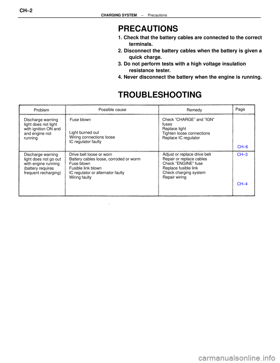
PRECAUTIONS
1. Check that the battery cables are connected to the correct
terminals.
2. Disconnect the battery cables when the battery is given a
quick charge.
3. Do not perform tests with a high voltage insulation
resistance tester.
4. Never disconnect the battery when the engine is running.
TROUBLESHOOTING
Drive belt loose or worn
Battery cables loose, corroded or worm
Fuse blown
Fusible link blown
IC regulator or alternator faulty
Wiring faultyAdjust or replace drive belt
Repair or replace cables
Check ºENGINEº fuse
Replace fusible link
Check charging system
Repair wiring Check ºCHARGEº and ºIGNº
fuses
Replace light
Tighten loose connections
Replace IC regulator
Discharge warning
light does not go out
with engine running
(battery requires
frequent recharging) Discharge warning
light does not light
with ignition ON and
and engine not
runningLight burned out
Wiring connections loose
IC regulator faultyPossible cause
Fuse blownRemedy
Problem
CH±6
CH±4 CH±3 Page
± CHARGING SYSTEMPrecautionsCH±2
Page 959 of 2389

PRECAUTIONS
1. Check that the battery cables are connected to the correct
terminals.
2. Disconnect the battery cables when the battery is given a
quick charge.
3. Do not perform tests with a high voltage insulation
resistance tester.
4. Never disconnect the battery when the engine is running.
TROUBLESHOOTING
Drive belt loose or worn
Battery cables loose, corroded or worm
Fuse blown
Fusible link blown
IC regulator or alternator faulty
Wiring faultyAdjust or replace drive belt
Repair or replace cables
Check ºENGINEº fuse
Replace fusible link
Check charging system
Repair wiring Check ºCHARGEº and ºIGNº
fuses
Replace light
Tighten loose connections
Replace IC regulator
Discharge warning
light does not go out
with engine running
(battery requires
frequent recharging) Discharge warning
light does not light
with ignition ON and
and engine not
runningLight burned out
Wiring connections loose
IC regulator faultyPossible cause
Fuse blownRemedy
Problem
CH±6
CH±4 CH±3 Page
± CHARGING SYSTEMTroubleshootingCH±2
Page 961 of 2389

HINT:
wºNew beltº refer to a belt which has been used 5 minutes
or less on a running engine.
wºUsed beltº refers to a belt which has been used on a running
engine for 5 minutes or more.
wAfter installing a belt, check that it fits properly in the
ribbed grooves.
wCheck by hand to confirm that the belt has not slipped out
of the groove on the bottom of the pulley.
wAfter installing a new belt, run the engine for about 5
minutes and recheck the belt tension.
4. VISUALLY CHECK ALTERNATOR WIRING AND
LISTEN FOR ABNORMAL NOISES
(a) Check that the wiring is in good condition.
(b) Check that there is no abnormal noise from the
alternator white the engine is running.
6. INSPECT CHARGING CIRCUIT WITHOUT LOAD
HINT: If a battery/alternator tester is available, connect the
tester to the charging circuit as per manufacturer's instruc-
tions.
(a) If a tester is not available, connect a voltmeter and ammeter
to the charging circuit as follows:
wDisconnect the wire from terminal B of the alternator and
connect it to the negative H probe of the ammeter.
wConnect the positive (+) probe of the ammeter to terminals
B of the alternator.
wConnect the positive (+) probe of the voltmeter to terminal
B of the alternator.
wGround the negative (±) probe of the voltmeter. 5. INSPECT CHARGE WARNING LIGHT CIRCUIT
(a) Warm up the engine and then turn it off.
(b) Turn off all accessories.
(c) Turn the ignition switch to ºONº. Check that the charge
warning light is lit.
(d) Start the engine. Check that the light goes out.
If the light does not go off as specified, troubleshoot the
charge light circuit.
± CHARGING SYSTEMOn±Vehicle InspectionCH±4
Page 962 of 2389

(b) Check the charging circuit as follows: .
With the engine running from idling to 2,000 rpm,
check the reading on the ammeter and voltmeter.
Standard amperage: 10 A or less
Standard voltage: 13.9 ± 15.1 V at 25
°C (77°F)
13.5 ± 14.3 V at 115°C (2390F)
If the voltmeter reading is greater than standard volt-
age, replace the IC regulator.
7. INSPECT CHARGING CIRCUIT WITH LOAD
(a) With the engine running at 2,000 rpm, turn on the high beam
headlights and place the heater blower switch at ºHlº.
(b) Check the reading on the ammeter.
Standard amperage: 30 A or more
If the ammeter reading is less than standard amperage,
repair the alternator. (See page CH±6)
HINT: With the battery fully charged, the indication will
sometimes be less than standard amperage. If the voltmeter reading is less than standard voltage,
check the IC regulator and alternator as follows:
wWith terminal F grounded, start the engine and check
the voltmeter reading of terminal B.
wIf the voltmeter reading is greater than standard voltage,
replace the IC regulator.
.. If the voltmeter reading is less than standard voltage,
check the alternator.
± CHARGING SYSTEMOn±Vehicle InspectionCH±5
Page 964 of 2389
REMOVAL OF ALTERNATOR (3S±FE)
1. DISCONNECT CABLE FROM NEGATIVE TERMINAL
OF BATTERY
2. DISCONNECT CONNECTOR AND WIRE FROM
ALTERNATOR
3. REMOVE DRIVE BELT
4. REMOVE ALTERNATOR
Remove the adjusting lock bolt, pivot bolt and alternator.
ALTERNATOR
COMPONENTS
± CHARGING SYSTEMAlternatorCH±6
Page 965 of 2389
REMOVAL OF ALTERNATOR (2VZ±FE)
1. DISCONNECT CABLE FROM NEGATIVE TERMINAL
OF BATTERY
2. REMOVE NO. 2 RH MOUNTING STAY
3. DISCONNECT CONNECTOR AND WIRE FROM
ALTERNATOR
4. DISCONNECT WIRE HARNESS FROM CLIP
5. REMOVE DRIVE BELT
6. REMOVE ALTERNATOR
Remove the adjusting lock bolt, pivot bolt and alternator.
DISASSEMBLY OF ALTERNATOR
(See page CH±6)
1. REMOVE REAR END COVER
(a) Remove the nut and terminal insulator.
(b) Remove the three nuts and end cover.
3. REMOVE RECTIFIER HOLDER
(a) Remove the four screws and rectifier holder.
(b) Remove the four rubber insulators.2. REMOVE BRUSH HOLDER AND IC REGULATOR
Remove the five screws, brush holder and IC regulator.
± CHARGING SYSTEMAlternatorCH±7