Page 1352 of 2389
39. PERFORM ENGINE ADJUSTMENT
(a) Adjust the alternator drive belt.
(See page CH±3)
Drive belt tension: New belt 175 + 5 Ib
Used belt 115 + 20 Ib
(b) Adjust PS pump drive belt.
Drive belt tension: New belt 125 + 25 Ib
Used belt 80 + 20 lb
(c) Adjust the ignition timing.
(See page IG±21 )
Ignition timing:
10°BTDC @ idle
(w/ Terminals TE1 and E1 connected)
(d) Adjust the valve clearance.
Valve clearance:
Intake 0.13 ± 0.23 mm (0. 005 ± 0.009 in.)
Exhaust 0.27 ± 0.37 mm l0.011 ± 0.015 in.)
40. INSTALL HOOD
41. PERFORM ROAD TEST
Check for abnormal noise, shock, slippage, correct shift
points and smooth operation.
42. RECHECK ENGINE COOLANT AND ENGINE OIL
LEVELS
± ENGINE MECHANICALCylinder Block (2VZ±FE)EM±175
Page 1903 of 2389
14. REMOVE TIMING BELT, NO.1 IDLER AND
CRANKSHAFT TIMING PULLEYS
(See pages EM±34 to 39)
15. (w/ A/C)
REMOVE ALTERNATOR (Seepage CH±6)
16. (w/ A/C)
REMOVE A/C COMPRESSOR WITHOUT
DISCONNECTING HOSES
(See step 28 on page EM±142)
17. (w/ A/C)
REMOVE A/C COMPRESSOR BRACKET
18. REMOVE PS BELT ADJUSTING BAR
19. REMOVE OIL PUMP
(a) Remove the nine bolts.
(b) Remove the oil pump by prying a screwdriver between the
oil pump and main bearing cap.
(c) Remove the 0±ring.13. SUSPEND ENGINE WITH ENGINE HOIST CHAIN
± LUBRICATION SYSTEMOil Pump (2VZ±FE)LU±18
Page 1908 of 2389

2. INSTALL PS BELT ADJUSTING BAR
3. (w/ A/C)
INSTALL A/C COMPRESSOR BRACKET
4. (w/ A/C)
INSTALL ALTERNATOR (Seepage CH±15)
5. (w/ A/C)
INSTALL A/C COMPRESSOR BRACKET
6. INSTALL CRANKSHAFT TIMING PULLEY, NO.1 IDLER
PULLEY AND TIMING BELT
(See pages EM±42 to 47)
7. REMOVE ENGINE HOIST CHAIN FROM ENGINE
8. INSTALL OIL PAN BAFFLE PLATE
(a) Remove any old packing (FIPG) material and be
careful not to drop any oil on the contact surfaces of
the baffle plate and cylinder block.
wUsing a razor blade and gasket scraper, remove
all the old packing (FIPG) material from the
gasket surfaces.
wThoroughly clean all components to remove all
the loose material.
wUsing a non±residue solvent, clean both sealing
surfaces.
NOTICE: Do not use a solvent which will affect the
painted surfaces.
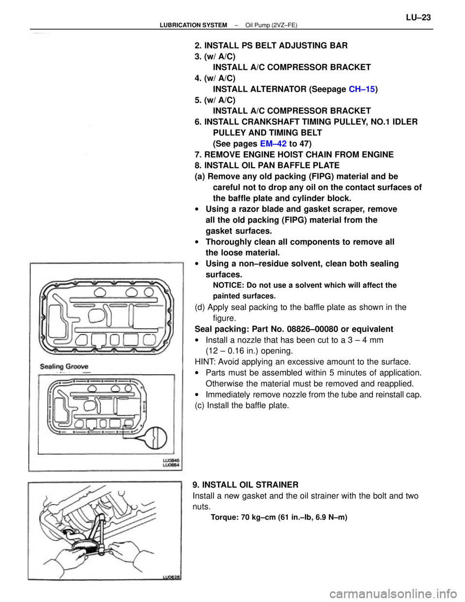
(d) Apply seal packing to the baffle plate as shown in the
figure.
Seal packing: Part No. 08826±00080 or equivalent
wInstall a nozzle that has been cut to a 3 ± 4 mm
(12 ± 0.16 in.) opening.
HINT: Avoid applying an excessive amount to the surface.
wParts must be assembled within 5 minutes of application.
Otherwise the material must be removed and reapplied.
wImmediately remove nozzle from the tube and reinstall cap.
(c) Install the baffle plate.
9. INSTALL OIL STRAINER
Install a new gasket and the oil strainer with the bolt and two
nuts.
Torque: 70 kg±cm (61 in.±Ib, 6.9 N±m)
± LUBRICATION SYSTEMOil Pump (2VZ±FE)LU±23
Page 1916 of 2389

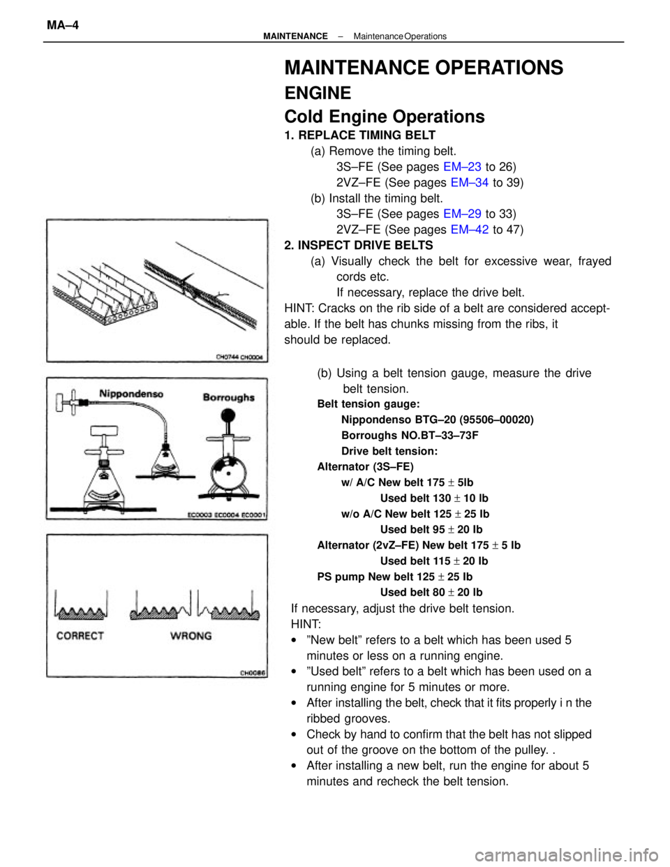
(b) Using a belt tension gauge, measure the drive
belt tension.
Belt tension gauge:
Nippondenso BTG±20 (95506±00020)
Borroughs NO.BT±33±73F
Drive belt tension:
Alternator (3S±FE)
w/ A/C New belt 175 + 5lb
Used belt 130 + 10 lb
w/o A/C New belt 125 + 25 Ib
Used belt 95 + 20 Ib
Alternator (2vZ±FE) New belt 175 + 5 Ib
Used belt 115 + 20 Ib
PS pump New belt 125 + 25 Ib
Used belt 80 + 20 lb
If necessary, adjust the drive belt tension.
HINT:
wºNew beltº refers to a belt which has been used 5
minutes or less on a running engine.
wºUsed beltº refers to a belt which has been used on a
running engine for 5 minutes or more.
wAfter installing the belt, check that it fits properly i n the
ribbed grooves.
wCheck by hand to confirm that the belt has not slipped
out of the groove on the bottom of the pulley. .
wAfter installing a new belt, run the engine for about 5
minutes and recheck the belt tension.
MAINTENANCE OPERATIONS
ENGINE
Cold Engine Operations
1. REPLACE TIMING BELT
(a) Remove the timing belt.
3S±FE (See pages EM±23 to 26)
2VZ±FE (See pages EM±34 to 39)
(b) Install the timing belt.
3S±FE (See pages EM±29 to 33)
2VZ±FE (See pages EM±42 to 47)
2. INSPECT DRIVE BELTS
(a) Visually check the belt for excessive wear, frayed
cords etc.
If necessary, replace the drive belt.
HINT: Cracks on the rib side of a belt are considered accept-
able. If the belt has chunks missing from the ribs, it
should be replaced.
± MAINTENANCEMaintenance OperationsMA±4
Page 2213 of 2389
Front and rear brake
Pad thickness
Disc thickness
Disc runout
Parking brake
Lining thickness
Drum inside diameter
Front axle and suspension
Ball joint vertical play
Steering wheel freeplay
Torque specifications
Front seat mount bolts
Strut/stabilizer bar bracket x Body
Engine mounting center member x Body
Front suspension lower crossmember x Body
Rear suspension lower crossmember x Body
MAINTENANCE
Engine
Engine oil capacity (Drain and refill with oil fitter change)
Gap
Firing order
Valve clearance Coolant capacity 1w/ Heater) Drive belt tension
Alternator
Spark plug
Type
Chassis
PS pump
± SERVICE SPECIFICATIONSMaintenanceA±2
Page 2216 of 2389
Spark plug tube x Cylinder head
Camshaft bearing cap x Cylinder head
Cylinder head cover x Cylinder head
Intake manifold x Cylinder head
Intake manifold stay x Cylinder head
Intake manifold stay x Cylinder block
EGR valve x Intake manifold
EGR pipe x Cylinder head
Water outlet x Cylinder head
Exhaust manifold x Catalytic converter
Exhaust manifold x Cylinder head
Engine hanger x Cylinder head
Alternator bracket x Cylinder headOil pump pulley x Oil pump drive shaft
No. 1 idler pulley x Cylinder head
No. 2 idler pulley x Cylinder block
Camshaft timing pulley x Camshaft
Crankshaft pulley x Crankshaft
Cylinder head x Cylinder block
Specifications (Cont'd)
Torque Specifications
Crankshaft
(cont'd)
Part tightened
± SERVICE SPECIFICATIONSEngine Mechanical (3S±FE)A±5
Page 2217 of 2389

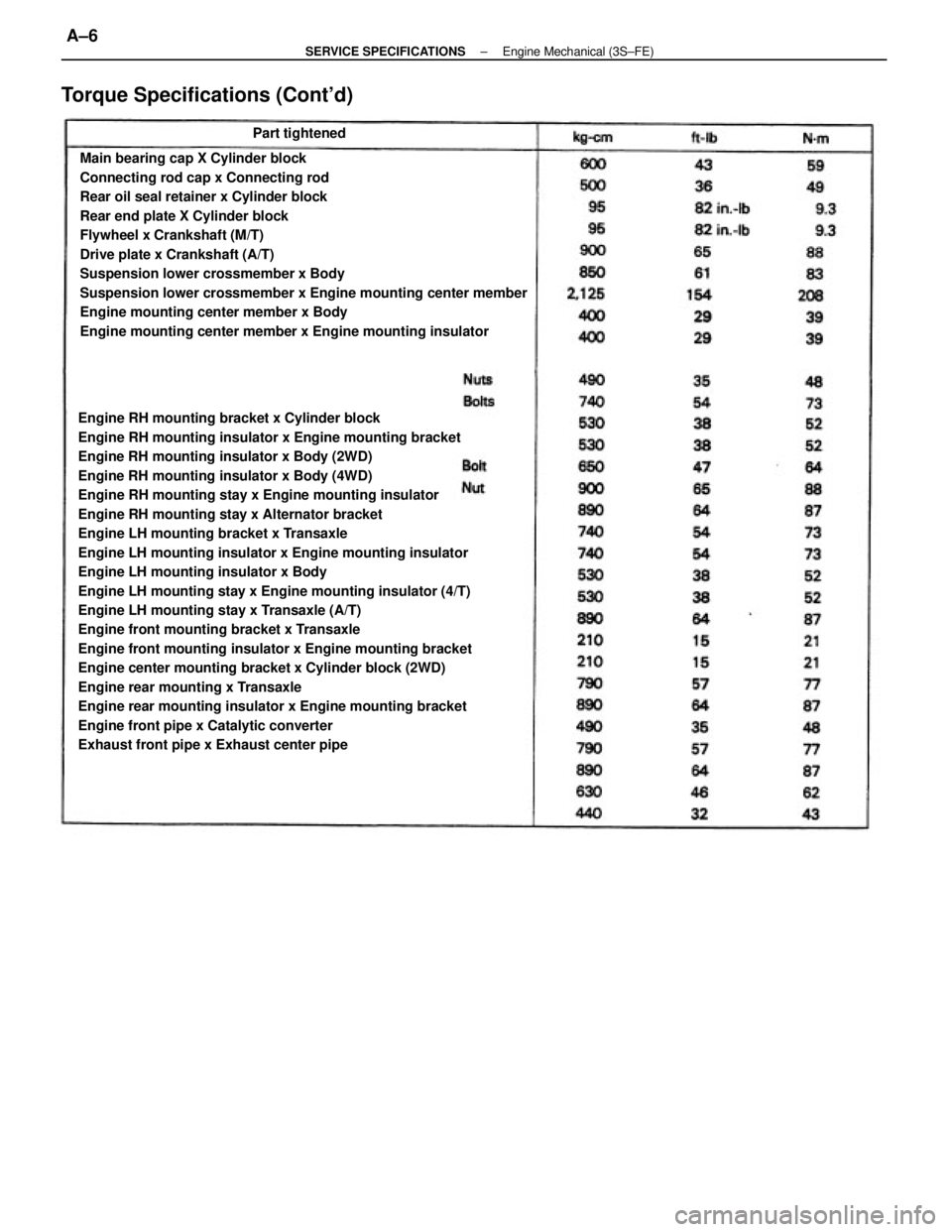
Engine RH mounting bracket x Cylinder block
Engine RH mounting insulator x Engine mounting bracket
Engine RH mounting insulator x Body (2WD)
Engine RH mounting insulator x Body (4WD)
Engine RH mounting stay x Engine mounting insulator
Engine RH mounting stay x Alternator bracket
Engine LH mounting bracket x Transaxle
Engine LH mounting insulator x Engine mounting insulator
Engine LH mounting insulator x Body
Engine LH mounting stay x Engine mounting insulator (4/T)
Engine LH mounting stay x Transaxle (A/T)
Engine front mounting bracket x Transaxle
Engine front mounting insulator x Engine mounting bracket
Engine center mounting bracket x Cylinder block (2WD)
Engine rear mounting x Transaxle
Engine rear mounting insulator x Engine mounting bracket
Engine front pipe x Catalytic converter
Exhaust front pipe x Exhaust center pipeMain bearing cap X Cylinder block
Connecting rod cap x Connecting rod
Rear oil seal retainer x Cylinder block
Rear end plate X Cylinder block
Flywheel x Crankshaft (M/T)
Drive plate x Crankshaft (A/T)
Suspension lower crossmember x Body
Suspension lower crossmember x Engine mounting center member
Engine mounting center member x Body
Engine mounting center member x Engine mounting insulator
Torque Specifications (Cont'd)
Part tightened
± SERVICE SPECIFICATIONSEngine Mechanical (3S±FE)A±6
Page 2221 of 2389

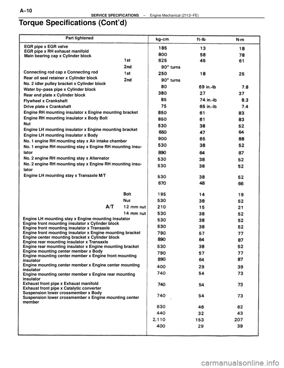
Connecting rod cap x Connecting rod
Rear oil seal retainer x Cylinder block
No. 2 idler pulley bracket x Cylinder block
Water by±pass pipe x Cylinder block
Rear end plate x Cylinder block
Flywheel x Crankshaft
Drive plate x Crankshaft
Engine RH mounting insulator x Engine mounting bracket
Engine RH mounting insulator x Body Bolt
Nut
Engine LH mounting insulator x Engine mounting bracket
Engine LH mounting insulator x Body
No. 1 engine RH mounting stay x Air intake chamber
No. 1 engine RH mounting stay x Engine RH mounting insu-
lator
No. 2 engine RH mounting stay x Alternator
No. 2 engine RH mounting stay x Engine RH mounting insu-
lator
Engine LH mounting stay x Transaxle M/T
Engine LH mounting stay x Engine mounting insulator
Engine front mounting insulator x Cylinder block
Engine front mounting insulator x Transaxle
Engine front mounting insulator x Engine mounting bracket
Engine center mounting bracket x Cylinder block
Engine rear mounting insulator x Transaxle
Engine rear mounting insulator x Engine mounting bracket
Engine mounting center member x Body
Engine mounting center member x Engine front mounting
insulator
Engine mounting center member x Engine center mounting
insulator
Engine mounting center member x Engine rear mounting
insulator
Exhaust front pipe x Exhaust manifold
Exhaust front pipe x Catalytic converter
Suspension lower crossmember x Body
Suspension lower crossmember x Engine mounting center
memberEGR pipe x EGR valve
EGR pipe x RH exhaust manifold
Main bearing cap x Cylinder block
Torque Specifications (Cont'd)
Part tightened
A/T
± SERVICE SPECIFICATIONSEngine Mechanical (2112±FE)A±10