1985 FORD GRANADA washer
[x] Cancel search: washerPage 110 of 255
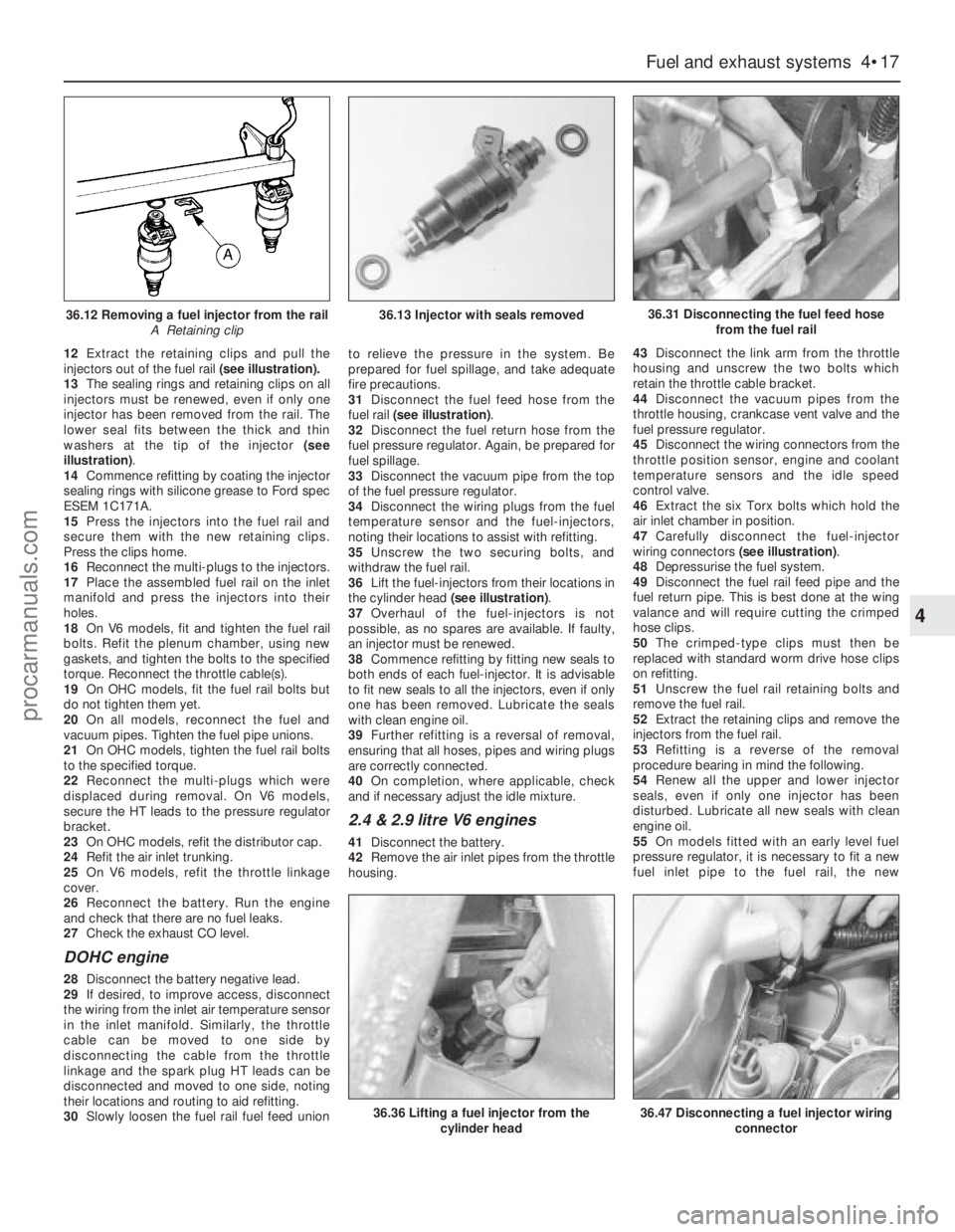
12Extract the retaining clips and pull the
injectors out of the fuel rail(see illustration).
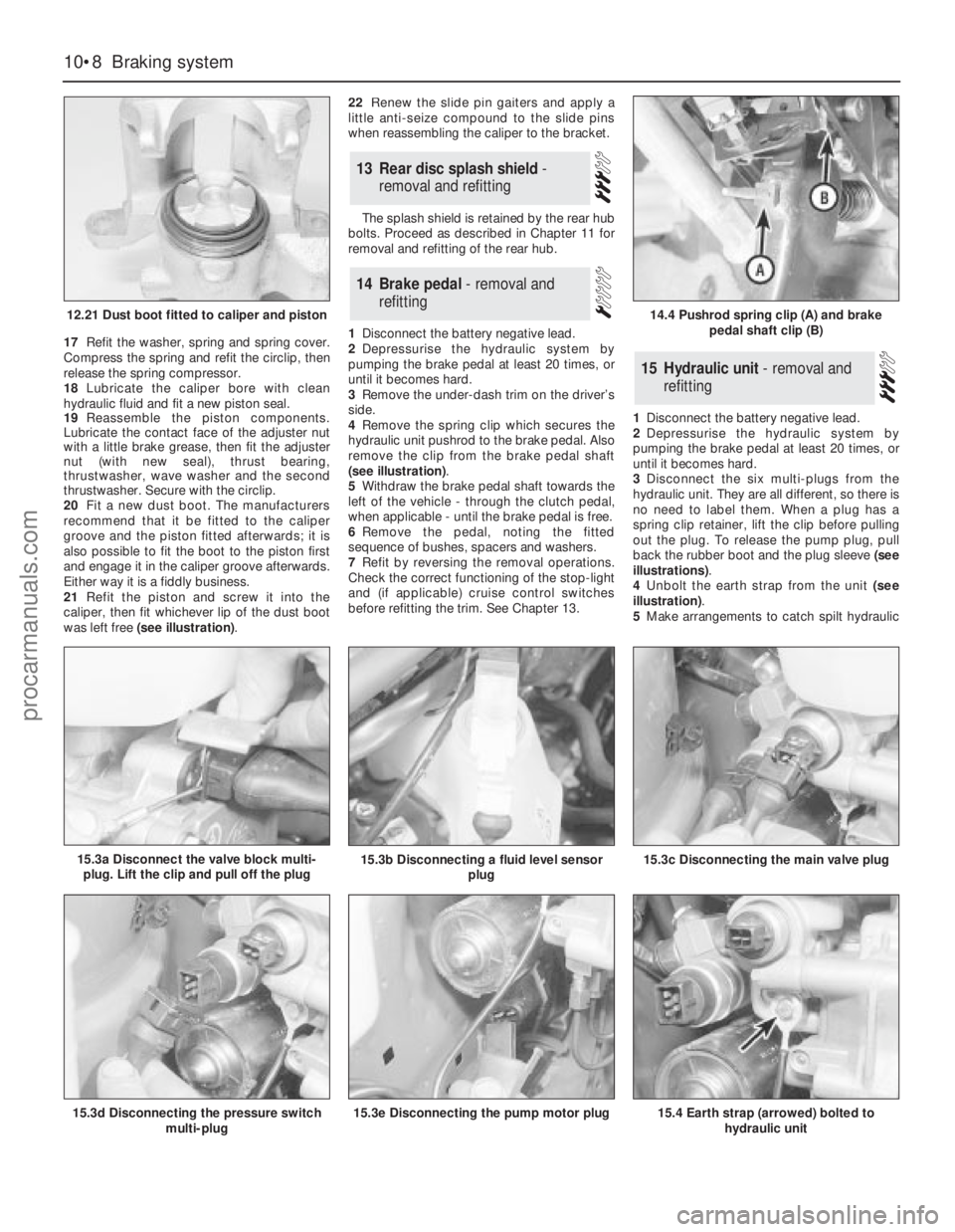
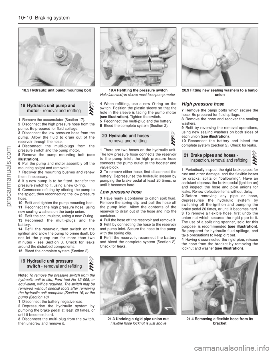
13The sealing rings and retaining clips on all
injectors must be renewed, even if only one
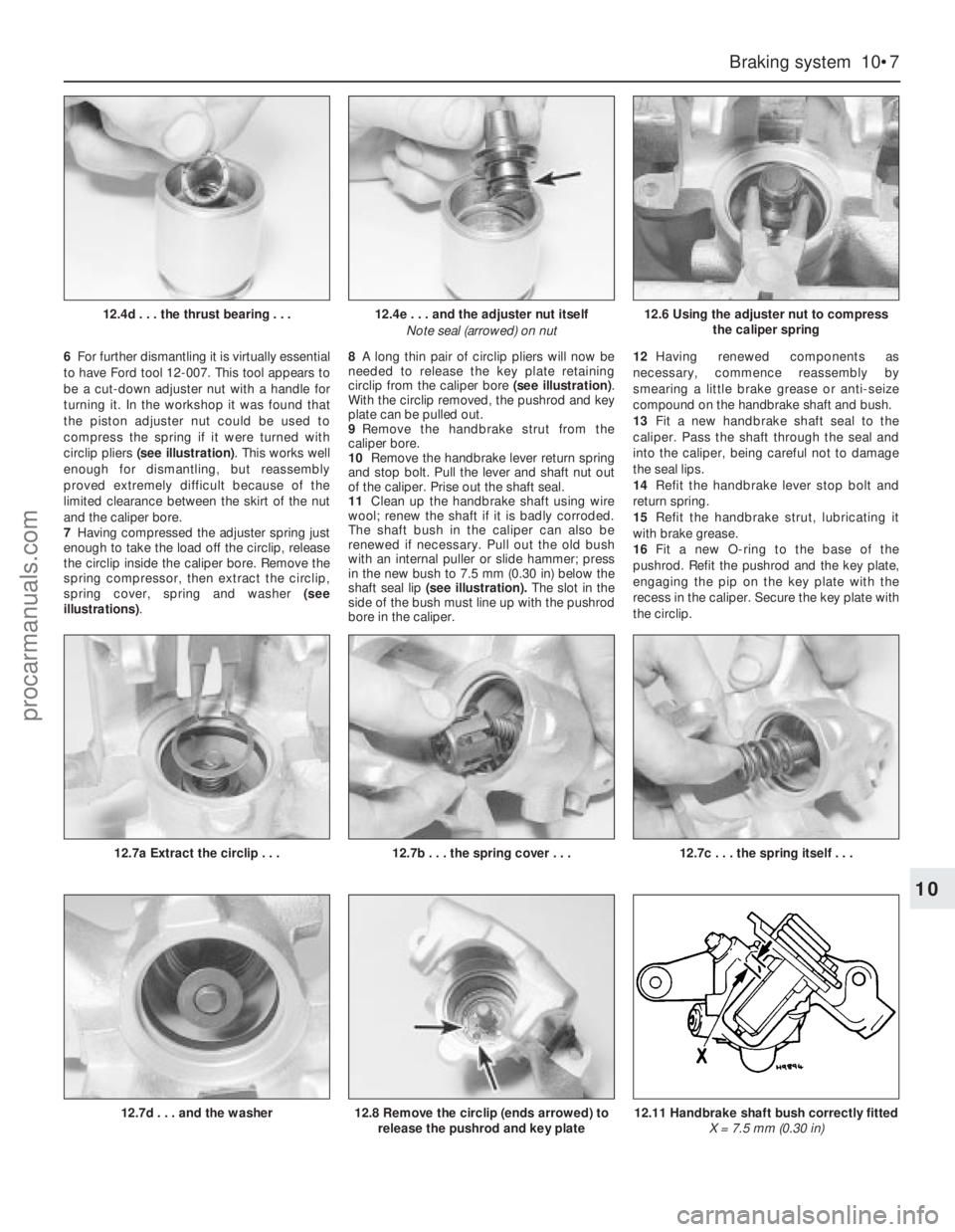
injector has been removed from the rail. The
lower seal fits between the thick and thin
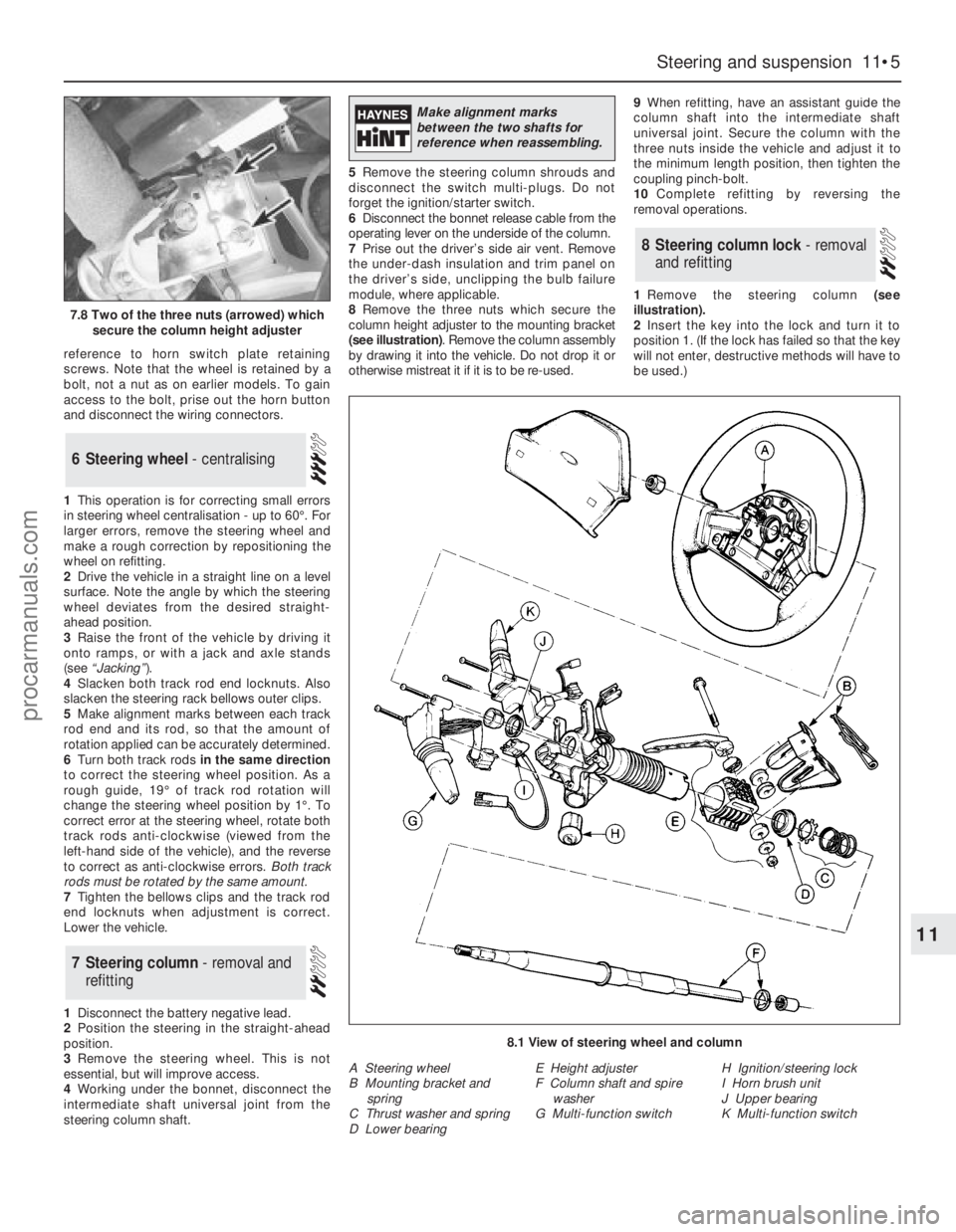
washers at the tip of the injector (see
illustration).
14Commence refitting by coating the injector
sealing rings with silicone grease to Ford spec
ESEM 1C171A.
15Press the injectors into the fuel rail and
secure them with the new retaining clips.
Press the clips home.
16Reconnect the multi-plugs to the injectors.
17Place the assembled fuel rail on the inlet
manifold and press the injectors into their
holes.
18On V6 models, fit and tighten the fuel rail
bolts. Refit the plenum chamber, using new
gaskets, and tighten the bolts to the specified
torque. Reconnect the throttle cable(s).
19On OHCmodels, fit the fuel rail bolts but
do not tighten them yet.
20On all models, reconnect the fuel and
vacuum pipes. Tighten the fuel pipe unions.
21On OHCmodels, tighten the fuel rail bolts
to the specified torque.
22Reconnect the multi-plugs which were
displaced during removal. On V6 models,
secure the HT leads to the pressure regulator
bracket.
23On OHCmodels, refit the distributor cap.
24Refit the air inlet trunking.
25On V6 models, refit the throttle linkage
cover.
26Reconnect the battery. Run the engine
and check that there are no fuel leaks.
27Check the exhaust CO level.
DOHC engine
28Disconnect the battery negative lead.
29If desired, to improve access, disconnect
the wiring from the inlet air temperature sensor
in the inlet manifold. Similarly, the throttle
cable can be moved to one side by
disconnecting the cable from the throttle
linkage and the spark plug HT leads can be
disconnected and moved to one side, noting
their locations and routing to aid refitting.
30Slowly loosen the fuel rail fuel feed unionto relieve the pressure in the system. Be
prepared for fuel spillage, and take adequate
fire precautions.
31Disconnect the fuel feed hose from the
fuel rail (see illustration).
32Disconnect the fuel return hose from the
fuel pressure regulator. Again, be prepared for
fuel spillage.
33Disconnect the vacuum pipe from the top
of the fuel pressure regulator.
34Disconnect the wiring plugs from the fuel
temperature sensor and the fuel-injectors,
noting their locations to assist with refitting.
35Unscrew the two securing bolts, and
withdraw the fuel rail.
36Lift the fuel-injectors from their locations in
the cylinder head (see illustration).
37Overhaul of the fuel-injectors is not
possible, as no spares are available. If faulty,
an injector must be renewed.
38Commence refitting by fitting new seals to
both ends of each fuel-injector. It is advisable
to fit new seals to all the injectors, even if only
one has been removed. Lubricate the seals
with clean engine oil.
39Further refitting is a reversal of removal,
ensuring that all hoses, pipes and wiring plugs
are correctly connected.
40On completion, where applicable, check
and if necessary adjust the idle mixture.
2.4 & 2.9 litre V6 engines
41Disconnect the battery.
42Remove the air inlet pipes from the throttle
housing.43Disconnect the link arm from the throttle
housing and unscrew the two bolts which
retain the throttle cable bracket.
44Disconnect the vacuum pipes from the
throttle housing, crankcase vent valve and the
fuel pressure regulator.
45Disconnect the wiring connectors from the
throttle position sensor, engine and coolant
temperature sensors and the idle speed
control valve.
46Extract the six Torx bolts which hold the
air inlet chamber in position.
47Carefully disconnect the fuel-injector
wiring connectors (see illustration).
48Depressurise the fuel system.
49Disconnect the fuel rail feed pipe and the
fuel return pipe. This is best done at the wing
valance and will require cutting the crimped
hose clips.
50The crimped-type clips must then be
replaced with standard worm drive hose clips
on refitting.
51Unscrew the fuel rail retaining bolts and
remove the fuel rail.
52Extract the retaining clips and remove the
injectors from the fuel rail.
53Refitting is a reverse of the removal
procedure bearing in mind the following.
54Renew all the upper and lower injector
seals, even if only one injector has been
disturbed. Lubricate all new seals with clean
engine oil.
55On models fitted with an early level fuel
pressure regulator, it is necessary to fit a new
fuel inlet pipe to the fuel rail, the new
Fuel and exhaust systems 4•17
4
36.12 Removing a fuel injector from the rail
A Retaining clip36.13 Injector with seals removed36.31 Disconnecting the fuel feed hose
from the fuel rail
36.36 Lifting a fuel injector from the
cylinder head36.47 Disconnecting a fuel injector wiring
connector
procarmanuals.com
Page 121 of 255
1Disconnect the battery negative (earth) lead.
2Disconnect the battery positive leads. These
may be protected by a plastic cover. Do not
allow the spanner to bridge the positive and
negative terminals.
3Release the battery hold-down clamp. Lift
out the battery. Keep it upright and be careful
not to drop it - it is heavy.
4Commence by placing the battery in its tray,
making sure it is the right way round. Secure it
with the hold-down clamp.
5Clean the battery terminals if necessary
then reconnect them. Connect the positive
lead first, then the negative lead.
1Should it appear that the alternator is not
charging the battery, check first that the
drivebelt is intact and in good condition and
that its tension is correct. Also check the
condition and security of the alternator
electrical connections and the battery leads.
2Accurate assessment of alternator output
requires special equipment and a degree of
skill. A rough idea of whether output is
adequate can be gained by using a voltmeter
(range 0 to 15 or 0 to 20 volts) as follows.
3Connect the voltmeter across the battery
terminals. Switch on the headlights and note
the voltage reading: it should be between 12
and 13 volts.
4Start the engine and run it at a fast idle
(approx 1500 rpm). Read the voltmeter: it
should indicate 13 to 14 volts.
5With the engine still running at a fast idle,
switch on as many electrical consumers as
possible (heated rear window, heater blower
etc). The voltage at the battery should be
maintained at 13 to 14 volts. Increase the
engine speed slightly if necessary to keep the
voltage up.
6If alternator output is low or zero, check the
brushes. If the brushes are OK, seek expert
advice.7Occasionally the condition may arise where
the alternator output is excessive. Clues to this
condition are constantly blowing bulbs;
brightness of lights vary considerably with
engine speed; overheating of alternator and
battery, possible with steam or fumes coming
from the battery. This condition is almost
certainly due to a defective voltage regulator,
but expert advice should be sought.
8Note that the alternator voltage regulator
can be renewed without removing the
alternator from the vehicle. The procedure is
part of brush renewal.
1Disconnect the battery negative lead.
2Disconnect the multi-plug from the rear of
the alternator. It may be secured by a wire clip.
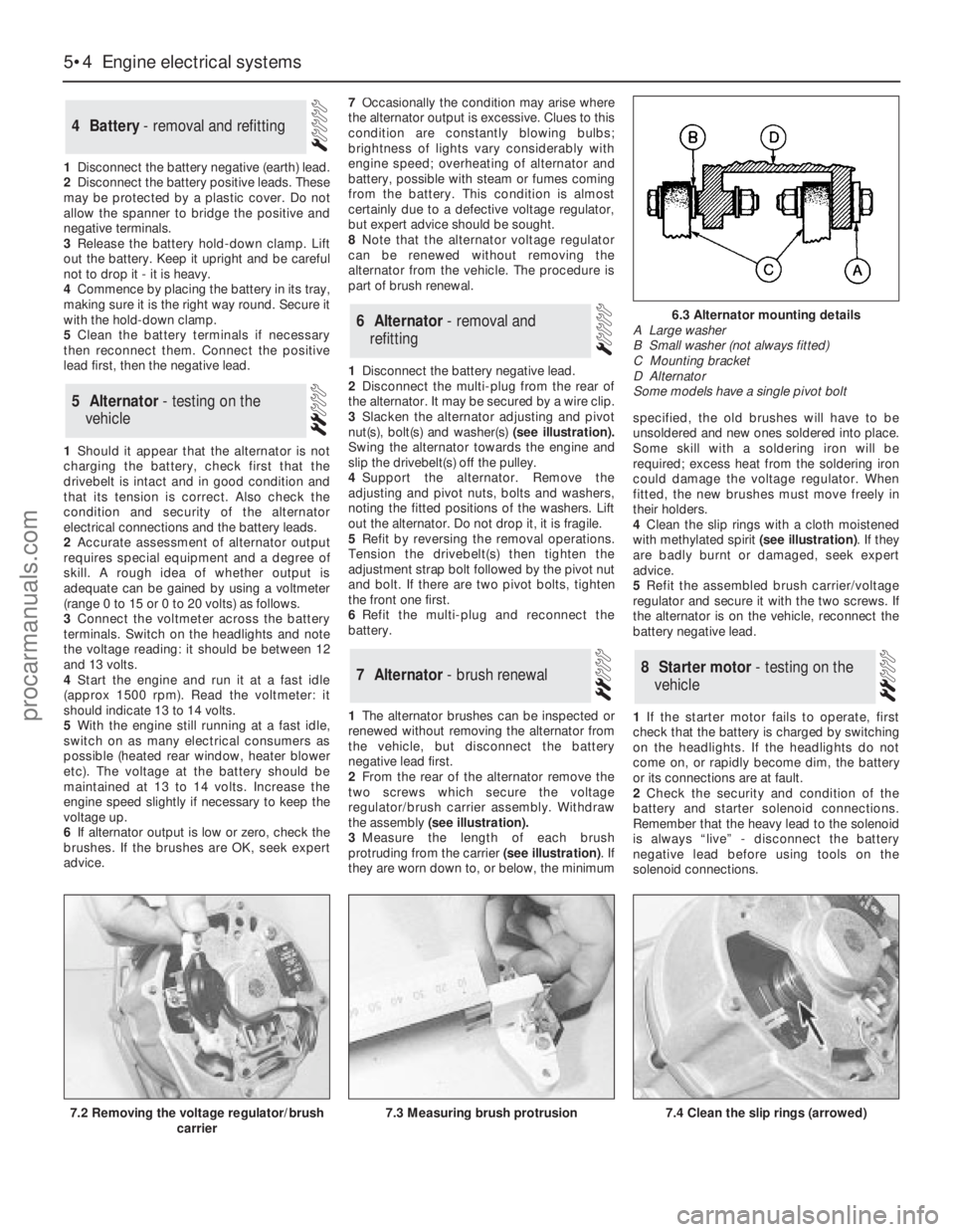
3Slacken the alternator adjusting and pivot
nut(s), bolt(s)and washer(s)(see illustration).
Swing the alternator towards the engine and
slip the drivebelt(s) off the pulley.
4Support the alternator. Remove the
adjusting and pivot nuts, bolts and washers,
noting the fitted positions of the washers. Lift
out the alternator. Do not drop it, it is fragile.
5Refit by reversing the removal operations.
Tension the drivebelt(s) then tighten the
adjustment strap bolt followed by the pivot nut
and bolt. If there are two pivot bolts, tighten
the front one first.
6Refit the multi-plug and reconnect the
battery.
1The alternator brushes can be inspected or
renewed without removing the alternator from
the vehicle, but disconnect the battery
negative lead first.
2From the rear of the alternator remove the
two screws which secure the voltage
regulator/brush carrier assembly. Withdraw
the assembly (see illustration).
3Measure the length of each brush
protruding from the carrier (see illustration). If
they are worn down to, or below, the minimumspecified, the old brushes will have to be
unsoldered and new ones soldered into place.
Some skill with a soldering iron will be
required; excess heat from the soldering iron
could damage the voltage regulator. When
fitted, the new brushes must move freely in
their holders.
4Clean the slip rings with a cloth moistened
with methylated spirit (see illustration). If they
are badly burnt or damaged, seek expert
advice.
5Refit the assembled brush carrier/voltage
regulator and secure it with the two screws. If
the alternator is on the vehicle, reconnect the
battery negative lead.
1If the starter motor fails to operate, first
check that the battery is charged by switching
on the headlights. If the headlights do not
come on, or rapidly become dim, the battery
or its connections are at fault.
2Check the security and condition of the
battery and starter solenoid connections.
Remember that the heavy lead to the solenoid
is always “live” - disconnect the battery
negative lead before using tools on the
solenoid connections.
8Starter motor - testing on the
vehicle7Alternator - brush renewal
6Alternator - removal and
refitting
5Alternator - testing on the
vehicle
4Battery - removal and refitting
5•4Engine electrical systems
7.3 Measuring brush protrusion7.4 Clean the slip rings (arrowed)
6.3 Alternator mounting details
A Large washer
B Small washer (not always fitted)
C Mounting bracket
D Alternator
Some models have a single pivot bolt
7.2 Removing the voltage regulator/brush
carrier
procarmanuals.com
Page 122 of 255
Solenoid check
3Disconnect the battery negative lead, and all
leads from the solenoid.
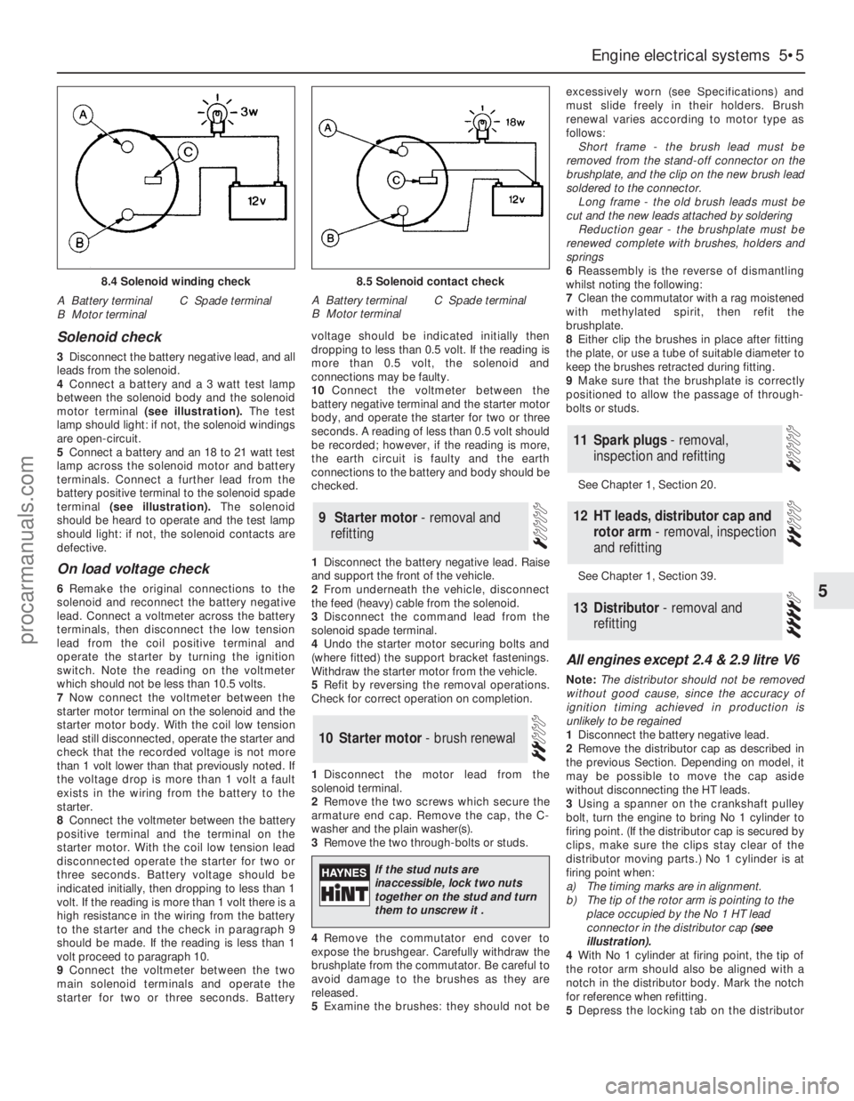
4Connect a battery and a 3 watt test lamp
between the solenoid body and the solenoid
motor terminal (see illustration).The test
lamp should light: if not, the solenoid windings
are open-circuit.
5Connect a battery and an 18 to 21 watt test
lamp across the solenoid motor and battery
terminals. Connect a further lead from the
battery positive terminal to the solenoid spade
terminal(see illustration).The solenoid
should be heard to operate and the test lamp
should light: if not, the solenoid contacts are
defective.
On load voltage check
6Remake the original connections to the
solenoid and reconnect the battery negative
lead. Connect a voltmeter across the battery
terminals, then disconnect the low tension
lead from the coil positive terminal and
operate the starter by turning the ignition
switch. Note the reading on the voltmeter
which should not be less than 10.5 volts.
7Now connect the voltmeter between the
starter motor terminal on the solenoid and the
starter motor body. With the coil low tension
lead still disconnected, operate the starter and
check that the recorded voltage is not more
than 1 volt lower than thatpreviously noted. If
the voltage drop is more than 1 volt a fault
exists in the wiring from the battery to the
starter.
8Connect the voltmeter between the battery
positive terminal and the terminal on the
starter motor. With the coil low tension lead
disconnected operate the starter for two or
three seconds. Battery voltage should be
indicated initially, then dropping to less than 1
volt. If the reading is more than 1 volt there is a
high resistance in the wiring from the battery
to the starter and the check in paragraph 9
should be made. If the reading is less than 1
volt proceed to paragraph 10.
9Connect the voltmeter between the two
main solenoid terminals and operate the
starter for two or three seconds. Batteryvoltage should be indicated initially then
dropping to less than 0.5 volt. If the reading is
more than 0.5 volt, the solenoid and
connections may be faulty.
10Connect the voltmeter between the
battery negative terminal and the starter motor
body, and operate the starter for two or three
seconds. A reading of less than 0.5 volt should
be recorded; however, if the reading is more,
the earth circuit is faulty and the earth
connections to the battery and body should be
checked.
1Disconnect the battery negative lead. Raise
and support the front of the vehicle.
2From underneath the vehicle, disconnect
the feed (heavy) cable from the solenoid.
3Disconnect the command lead from the
solenoid spade terminal.
4Undo the starter motor securing bolts and
(where fitted) the support bracket fastenings.
Withdraw the starter motor from the vehicle.
5Refit by reversing the removal operations.
Check for correct operation on completion.
1Disconnect the motor lead from the
solenoid terminal.
2Remove the two screws which secure the
armature end cap. Remove the cap, the C-
washer and the plain washer(s).
3Remove the two through-bolts or studs.
4Remove the commutator end cover to
expose the brushgear. Carefully withdraw the
brushplate from the commutator. Be careful to
avoid damage to the brushes as they are
released.
5Examine the brushes: they should not beexcessively worn (see Specifications) and
must slide freely in their holders. Brush
renewal varies according to motor type as
follows:
Short frame - the brush lead must be
removed from the stand-off connector on the
brushplate, and the clip on the new brush lead
soldered to the connector.
Long frame - the old brush leads must be
cut and the new leads attached by soldering
Reduction gear - the brushplate must be
renewed complete with brushes, holders and
springs
6Reassembly is the reverse of dismantling
whilst noting the following:
7Clean the commutator with a rag moistened
with methylated spirit, then refit the
brushplate.
8Either clip the brushes in place after fitting
the plate, or use a tube of suitable diameter to
keep the brushes retracted during fitting.
9Make sure that the brushplate is correctly
positioned to allow the passage of through-
bolts or studs.
See Chapter 1, Section 20.
See Chapter 1, Section 39.
All engines except 2.4 & 2.9 litre V6
Note: The distributor should not be removed
without good cause, since the accuracy of
ignition timing achieved in production is
unlikely to be regained
1Disconnect the battery negative lead.
2Remove the distributor cap as described in
the previous Section. Depending on model, it
may be possible to move the cap aside
without disconnecting the HT leads.
3Using a spanner on the crankshaft pulley
bolt, turn the engine to bring No 1 cylinder to
firing point. (If the distributor cap is secured by
clips, make sure the clips stay clear of the
distributor moving parts.) No 1 cylinder is at
firing point when:
a)The timing marks are in alignment.
b)The tip of the rotor arm is pointing to the
place occupied by the No 1 HT lead
connector in the distributor cap (see
illustration).
4With No 1 cylinder at firing point, the tip of
the rotor arm should also be aligned with a
notch in the distributor body. Mark the notch
for reference when refitting.
5Depress the locking tab on the distributor
13Distributor - removal and
refitting
12HT leads, distributor cap and
rotor arm - removal, inspection
and refitting
11Spark plugs - removal,
inspection and refitting
10Starter motor - brush renewal
9Starter motor - removal and
refitting
Engine electrical systems 5•5
5
8.4 Solenoid winding check
A Battery terminal
B Motor terminalC Spade terminal
8.5 Solenoid contact check
A Battery terminal
B Motor terminalC Spade terminal
If the stud nuts are
inaccessible, lock two nuts
together on the stud and turn
them to unscrew it .
procarmanuals.com
Page 135 of 255
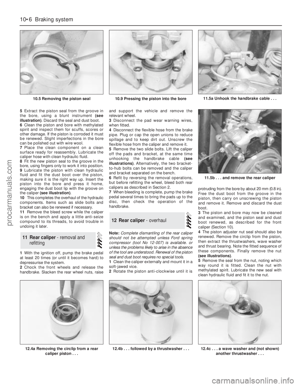
5Extract the piston seal from the groove in
the bore, using a blunt instrument (see
illustration). Discard the seal and dust boot.
6Clean the piston and bore with methylated
spirit and inspect them for scuffs, scores or
other damage. If the piston is corroded it must
be renewed. Slight imperfections in the bore
can be polished out with wire wool.
7Place the clean component on a clean
surface ready for reassembly. Lubricate the
caliper hose with clean hydraulic fluid.
8Fit the new piston seal to the groove in the
bore, using fingers only to work it into position.
9Lubricate the piston with clean hydraulic
fluid and fit the dust boot over the piston,
making sure it is the right way up. Insert the
piston into the bore and press it home,
engaging the dust boot lip with the groove on
the caliper (see illustration).
10This completes the overhaul of the hydraulic
components. Items such as slide bolts and
bracket can also be renewed if necessary.
11Remove the bleed screw while the caliper
is on the bench and apply a little anti-seize
compound to its threads, to avoid trouble in
undoing it later.
1With the ignition off, pump the brake pedal
at least 20 times (or until it becomes hard) to
depressurise the system.
2Chock the front wheels and release the
handbrake. Slacken the rear wheel nuts, raiseand support the vehicle and remove the
relevant wheel.
3Disconnect the pad wear warning wires,
when fitted.
4Disconnect the flexible hose from the brake
pipe. Plug or cap the open unions to reduce
spillage and to keep dirt out. Unscrew the
flexible hose from the caliper and remove it.
5Remove the two slide bolts. Lift the caliper
off the pads and bracket, at the same time
unhooking the handbrake cable (see
illustrations). Alternatively, the two bracket-
to-hub bolts can be removed and the caliper
and bracket separated on the bench.
6Refit by reversing the removal operations,
but before refitting the wheel, bleed both rear
calipers as described in Section 2.
7When bleeding is complete, pump the brake
pedal several times to bring the pads up to the
disc, then check the operation of the
handbrake.
Note: Complete dismantling of the rear caliper
should not be attempted unless Ford spring
compressor (tool No 12-007) is available. or
unless the problems likely to arise in the absence
of the tool are understood. Renewal of the piston
seal and dust boot requires no special tools.
1Clean the caliper externally and mount it in a
soft-jawed vice.
2Rotate the piston anti-clockwise until it isprotruding from the bore by about 20 mm (0.8 in).
Free the dust boot from the groove in the
piston, then carry on unscrewing the piston
and remove it. Remove and discard the dust
boot.
3The piston and bore may now be cleaned
and examined, and the piston seal and dust
boot renewed, as described for the front
caliper (Section 10).
4The piston adjuster nut seal should also be
renewed. Remove the circlip from the piston,
then extract the thrustwashers, wave washer
and thrust bearing. Note the fitted sequence of
these components. Finally remove the nut
(see illustrations).
5Remove the seal from the nut, noting which
way round it is fitted. Clean the nut with
methylated spirit. Lubricate the new seal with
clean hydraulic fluid and fit it to the nut.
12Rear caliper - overhaul
11Rear caliper - removal and
refitting
10•6Braking system
10.5 Removing the piston seal
12.4a Removing the circlip from a rear
caliper piston . . .12.4b . . . followed by a thrustwasher . . .
11.5b . . . and remove the rear caliper
10.9 Pressing the piston into the bore11.5a Unhook the handbrake cable . . .
12.4c . . . a wave washer and (not shown)
another thrustwasher . . .
procarmanuals.com
Page 136 of 255
6For further dismantling it is virtually essential
to have Ford tool 12-007. This tool appears to
be a cut-down adjuster nut with a handle for
turning it. In the workshop it was found that
the piston adjuster nut could be used to
compress the spring if it were turned with
circlip pliers (see illustration). This works well
enough for dismantling, but reassembly
proved extremely difficult because of the
limited clearance between the skirt of the nut
and the caliper bore.
7Having compressed the adjuster spring just
enough to take the load off the circlip, release
the circlip inside the caliper bore. Remove the
spring compressor, then extract the circlip,
spring cover, spring and washer (see
illustrations). 8A long thin pair of circlip pliers will now be
needed to release the key plate retaining
circlip from the caliper bore (see illustration).
With the circlip removed, the pushrod and key
plate can be pulled out.
9Remove the handbrake strut from the
caliper bore.
10Remove the handbrake lever return spring
and stop bolt. Pull the lever and shaft nut out
of the caliper. Prise out the shaft seal.
11Clean up the handbrake shaft using wire
wool; renew the shaft if it is badly corroded.
The shaft bush in the caliper can also be
renewed if necessary. Pull out the old bush
with an internal puller or slide hammer; press
in the new bush to 7.5 mm (0.30 in) below the
shaft seal lip(seeillustration).The slot in the
side of the bush must line up with the pushrod
bore in the caliper.12Having renewed components as
necessary, commence reassembly by
smearing a little brake grease or anti-seize
compound on the handbrake shaft and bush.
13Fit a new handbrake shaft seal to the
caliper. Pass the shaft through the seal and
into the caliper, being careful not to damage
the seal lips.
14Refit the handbrake lever stop bolt and
return spring.
15Refit the handbrake strut, lubricating it
with brake grease.
16Fit a new O-ring to the base of the
pushrod. Refit the pushrod and the key plate,
engaging the pip on the key plate with the
recess in the caliper. Secure the key plate with
the circlip.
Braking system 10•7
10
12.4e . . . and the adjuster nut itself
Note seal (arrowed) on nut
12.7c . . . the spring itself . . .
12.6 Using the adjuster nut to compress
the caliper spring
12.7a Extract the circlip . . .12.7b . . . the spring cover . . .
12.7d . . . and the washer12.11 Handbrake shaft bush correctly fitted
X = 7.5 mm (0.30 in)12.8 Remove the circlip (ends arrowed) to
release the pushrod and key plate
12.4d . . . the thrust bearing . . .
procarmanuals.com
Page 137 of 255
17Refit the washer, spring and spring cover.
Compress the spring and refit the circlip, then
release the spring compressor.
18Lubricate the caliper bore with clean
hydraulic fluid and fit a new piston seal.
19Reassemble the piston components.
Lubricate the contact face of the adjuster nut
with a little brake grease, then fit the adjuster
nut (with new seal), thrust bearing,
thrustwasher, wave washer and the second
thrustwasher. Secure with the circlip.
20Fit a new dust boot. The manufacturers
recommend that it be fitted to the caliper
groove and the piston fitted afterwards; it is
also possible to fit the boot to the piston first
and engage it in the caliper groove afterwards.
Either way it is a fiddly business.
21Refit the piston and screw it into the
caliper, then fit whichever lip of the dust boot
was left free (see illustration).22Renew the slide pin gaiters and apply a
little anti-seize compound to the slide pins
when reassembling the caliper to the bracket.
The splash shield is retained by the rear hub
bolts. Proceed as described in Chapter 11 for
removal and refitting of the rear hub.
1Disconnect the battery negative lead.
2Depressurise the hydraulic system by
pumping the brake pedal at least 20 times, or
until it becomes hard.
3Remove the under-dash trim on the driver’s
side.
4Remove the spring clip which secures the
hydraulic unit pushrod to the brake pedal. Also
remove the clip from the brake pedal shaft
(see illustration).
5Withdraw the brake pedal shaft towards the
left of the vehicle - through the clutch pedal,
when applicable - until the brake pedal is free.
6Remove the pedal, noting the fitted
sequence of bushes, spacers and washers.
7Refit by reversing the removal operations.
Check the correct functioning of the stop-light
and (if applicable) cruise control switches
before refitting the trim. See Chapter 13.1Disconnect the battery negative lead.
2Depressurise the hydraulic system by
pumping the brake pedal at least 20 times, or
until it becomes hard.
3Disconnect the six multi-plugs from the
hydraulic unit. They are all different, so there is
no need to label them. When a plug has a
spring clip retainer, lift the clip before pulling
out the plug. To release the pump plug, pull
back the rubber boot and the plug sleeve (see
illustrations).
4Unbolt the earth strap from the unit (see
illustration).
5Make arrangements to catch spilt hydraulic
15Hydraulic unit - removal and
refitting
14Brake pedal - removal and
refitting
13Rear disc splash shield -
removal and refitting
10•8Braking system
12.21 Dust boot fitted to caliper and piston
15.3d Disconnecting the pressure switch
multi-plug15.3e Disconnecting the pump motor plug15.4 Earth strap (arrowed) bolted to
hydraulic unit
14.4 Pushrod spring clip (A) and brake
pedal shaft clip (B)
15.3a Disconnect the valve block multi-
plug. Lift the clip and pull off the plug15.3b Disconnecting a fluid level sensor
plug15.3c Disconnecting the main valve plug
procarmanuals.com
Page 139 of 255
1Remove the accumulator (Section 17).
2Disconnect the high pressure hose from the
pump. Be prepared for fluid spillage.
3Disconnect the low pressure hose from the
pump. Allow the fluid to drain out of the
reservoir through the hose.
4Disconnect the multi-plugs from the
pressure switch and the pump motor.
5Remove the pump mounting bolt (see
illustration).
6Pull the pump and motor assembly off the
mounting spigot and remove it.
7Recover the mounting bushes and renew
them if necessary.
8If a new pump is to be fitted, transfer the
pressure switch to it, using a new O-ring.
9Commence refitting by offering the pump to
the spigot, then reconnecting the low pressure
hose.
10Refit and tighten the pump mounting bolt.
11Reconnect the high pressure hose, using
new sealing washers on the banjo union.
12Refit the accumulator, using a new O-ring.
13Reconnect the multi-plugs and the
battery.
14Refill the reservoir, then switch on the
ignition and allow the pump to prime itself. Do
not let the pump run for more than two
minutes - see Section 3. Check for leaks
around the disturbed components.
15Bleed the complete system (Section 2).
Note: To remove the pressure switch from the
hydraulic unit in situ, Ford tool No 12-008, or
equivalent, will be required. The switch may be
removed without special tools after removing
the hydraulic unit complete (Section 16) or the
pump (Section 18).
1Disconnect the battery negative lead.
2Depressurise the hydraulic system by
pumping the brake pedal at least 20 times, or
until it becomes hard.
3Disconnect the multi-plug from the switch,
then unscrew and remove it.4When refitting, use a new O-ring on the
switch. Position the plastic sleeve so that the
hole in the sleeve is facing the pump motor
(see illustration). Tighten the switch.
5Reconnect the multi-plug and the battery.
6Bleed the complete system (Section 2).
1There are two hoses on the hydraulic unit.
The low pressure hose connects the reservoir
to the pump inlet; the high pressure hose
connects the pump outlet to the booster and
valve block.
2To remove either hose, first disconnect the
battery. Depressurise the hydraulic system by
pumping the brake pedal at least 20 times, or
until it becomes hard.
Low pressure hose
3Have ready a container to catch spilt fluid.
Remove the spring clip and pull the hose off
the pump inlet. Allow the contents of the
reservoir to drain out of the hose and into the
container.
4Pull the hose off the reservoir and remove it.
5Refit by connecting the hose to the reservoir
and pump inlet. Secure the hose to the pump
with the spring clip.
6Refill the reservoir, reconnect the battery
and bleed the complete system (Section 2).
Check for leaks.
High pressure hose
7Remove the banjo bolts which secure the
hose. Be prepared for fluid spillage.
8Remove the hose and recover the sealing
washers.
9Refit by reversing the removal operations,
using new sealing washers on both sides of
each union (see illustration).
10Reconnect the battery and bleed the
complete system (Section 2). Check for leaks.
1Periodically inspect the rigid brake pipes for
rust and other damage, and the flexible hoses
for cracks, splits or “ballooning”. Have an
assistant depress the brake pedal (ignition on)
and inspect the hose and pipe unions for
leaks. Renew defective items without delay.
2Before removing any pipe or hose,
depressurise the hydraulic system by
switching off the ignition and pumping the
brake pedal 20 times, or until it becomes hard.
3To remove a flexible hose, first undo the
union nut which secures the rigid pipe to it.
The use of a split ring spanner, sold for this
purpose, is recommended (see illustration).
Be prepared for hydraulic fluid spillage, and
take precautions to keep dirt out.
4Having disconnected the rigid pipe, release
the hose from the bracket by removing the
locknut and washer (see illustration).
21Brake pipes and hoses -
inspection, removal and refitting
20Hydraulic unit hoses -
removal and refitting
19Hydraulic unit pressure
switch - removal and refitting
18Hydraulic unit pump and
motor - removal and refitting
10•10Braking system
18.5 Hydraulic unit pump mounting bolt
21.3 Undoing a rigid pipe union nut
Flexible hose locknut is just above21.4 Removing a flexible hose from its
bracket
19.4 Refitting the pressure switch
Hole (arrowed) in sleeve must face pump motor20.9 Fitting new sealing washers to a banjo
union
procarmanuals.com
Page 148 of 255
reference to horn switch plate retaining
screws. Note that the wheel is retained by a
bolt, not a nut as on earlier models. To gain
access to the bolt, prise out the horn button
and disconnect the wiring connectors.
1This operation is for correcting small errors
in steering wheel centralisation - up to 60°. For
larger errors, remove the steering wheel and
make a rough correction by repositioning the
wheel on refitting.
2Drive the vehicle in a straight line on a level
surface. Note the angle by which the steering
wheel deviates from the desired straight-
ahead position.
3Raise the front of the vehicle by driving it
onto ramps, or with a jack and axle stands
(see “Jacking”).
4Slacken both track rod end locknuts. Also
slacken the steering rack bellows outer clips.
5Make alignment marks between each track
rod end and its rod, so that the amount of
rotation applied can be accurately determined.
6Turn both track rodsin the same direction
to correct the steering wheel position. As a
rough guide, 19°of track rod rotation will
change the steering wheel position by 1°. To
correct error at the steering wheel, rotate both
track rods anti-clockwise (viewed from the
left-hand side of the vehicle), and the reverse
to correct as anti-clockwise errors. Both track
rods must be rotated by the same amount.
7Tighten the bellows clips and the track rod
end locknuts when adjustment is correct.
Lower the vehicle.
1Disconnect the battery negative lead.
2Position the steering in the straight-ahead
position.
3Remove the steering wheel. This is not
essential, but will improve access.
4Working under the bonnet, disconnect the
intermediate shaft universal joint from the
steering column shaft.5Remove the steering column shrouds and
disconnect the switch multi-plugs. Do not
forget the ignition/starter switch.
6Disconnect the bonnet release cable from the
operating lever on the underside of the column.
7Prise out the driver’s side air vent. Remove
the under-dash insulation and trim panel on
the driver’s side, unclipping the bulb failure
module, where applicable.
8Remove the three nuts which secure the
column height adjuster to the mounting bracket
(see illustration). Remove the column assembly
by drawing it into the vehicle. Do not drop it or
otherwise mistreat it if it is to be re-used.9When refitting, have an assistant guide the
column shaft into the intermediate shaft
universal joint. Secure the column with the
three nuts inside the vehicle and adjust it to
the minimum length position, then tighten the
coupling pinch-bolt.
10Complete refitting by reversing the
removal operations.
1Remove the steering column (see
illustration).
2Insert the key into the lock and turn it to
position 1. (If the lock has failed so that the key
will not enter, destructive methods will have to
be used.)
8Steering column lock - removal
and refitting
7Steering column - removal and
refitting
6Steering wheel - centralising
Steering and suspension 11•5
11
7.8 Two of the three nuts (arrowed) which
secure the column height adjuster
8.1 View of steering wheel and column
A Steering wheel
B Mounting bracket and
spring
C Thrust washer and spring
D Lower bearingE Height adjuster
F Column shaft and spire
washer
G Multi-function switchH Ignition/steering lock
I Horn brush unit
J Upper bearing
K Multi-function switch
Make alignment marks
between the two shafts for
reference when reassembling.
procarmanuals.com