1985 FORD GRANADA washer
[x] Cancel search: washerPage 13 of 255
1Work around the vehicle, and lubricate the
hinges and locks with a light machine oil.
2Lightly lubricate the bonnet release
mechanism and exposed sections of inner
cable with a smear of grease.
3Check the security and operation of all
hinges, latches and locks, adjusting them
where required. Where applicable, check the
operation of the central locking system.
4Check the condition and operation of the
tailgate struts, renewing them if either is
leaking or is no longer able to support the
tailgate securely when raised.
SOHC and V6 engines
1The correct functioning of the spark plugs is
vital for the correct running and efficiency of
the engine. It is essential that the plugs fitted
are appropriate for the engine.
2Make sure that the ignition is switched off
before inspecting the HT leads to see if they
carry their cylinder numbers - if not, number
each lead using sticky tape or paint.
3Pull the HT lead connectors off the plugs.
Pull on the connectors, not on the leads.
4Blow away any dirt from around the spark
plug recesses in the cylinder head(s).
5Unscrew and remove the plugs, using a
proprietary plug spanner or a spark plug
socket, extension and ratchet.
6The condition of the plugs will tell much
about the overall condition of the engine. If the
insulator nose of the spark plug is clean and
white, with no deposits, this is indicative of a
weak mixture or too hot a plug (a hot plug
transfers heat away from the electrode slowly,
a cold plug transfers heat away quickly).
7If the tip and insulator nose are covered with
hard black-looking deposits, then this is
indicative that the mixture is too rich. Should
the plug be black and oily, then it is likely that
the engine is fairly worn, as well as the mixture
being too rich.
8If the insulator nose is covered with light tan
to greyish-brown deposits, then the mixture is
correct, and it is likely that the engine is in
good condition.
9Apply a smear of anti-seize compound to
the threads of the new plugs. Make sure that
theinsulators are clean and that the screwed
HT lead adapters are tight. Pay particular
attention to the plug seating surfaces on OHC
engines, since these plugs have no sealing
washers (“taper seat” type) and any dirt will
cause a bad seal.
10Screw each plug into its hole by hand. If a
plug is reluctant to go in, do not force it with a
spanner, but unscrew it and try again. If the
plug is cross-threaded, it is the cylinder head
which will be damaged.11Final tightening of the spark plugs should
ideally be carried out using a torque wrench.
The tightening torques are given in the
Specifications. If a torque wrench is not
available, tighten the plugs beyond the point
where they contact the head as follows:
OHC (taper seat plugs) - One-sixteenth of a
turn maximum
V6 (plugs with washers) - One-quarter of a
turn maximum
12If the taper seat type of plug is
overtightened, the sealing faces will bite
together and removal will be very difficult.
13Refit the HT leads to the plugs, paying
attention to the cylinder numbers. Push each
connector firmly onto its plug.
14Run the engine to verify that the HT leads
have been refitted correctly.
DOHC engines
15Proceed as described above whilst noting
the following points.
a)Remove the air cleaner as described in
Chapter 4.
b)The minimal length of number 3 HT lead
makes removal from the spark plug
difficult. It is advisable to remove this lead
from the distributor prior to removing it
from the spark plug.
c)The spark plugs are deeply recessed in
the cylinder head and it will be necessary
to use a spark plug socket with a long
extension bar. If possible, use a spark plug
socket with a rubber grip inside as this will
hold onto the spark plug once loosened
and will enable the spark plugs to be
withdrawn and refitted more easily.
SOHC and all V6 engines
1All of these engines have one or two
drivebelts which drive the water pump and
alternator from the crankshaft pulley. When
power steering is fitted, the same belts drive
the steering pump. The air conditioning
compressor, when fitted, is driven
independently.
2Periodically inspect the drivebelt(s) for
fraying, cracks, glazing or other damage. Turn
the engine so that the full length of the belt(s)
can be viewed. Renew belts which are in poor
condition. When twin drivebelts are fitted, both
must be renewed together, even if only one is
damaged.
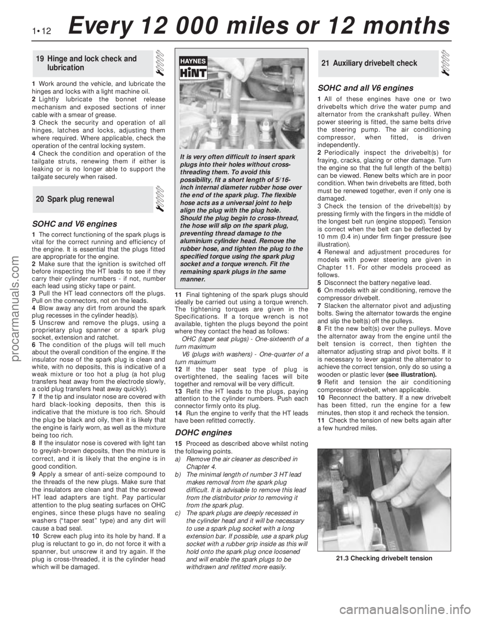
3Check the tension of the drivebelt(s) by
pressing firmly with the fingers in the middle of
the longest belt run (engine stopped). Tension
is correct when the belt can be deflected by
10 mm (0.4 in) under firm finger pressure (see
illustration).
4Renewal and adjustment procedures for
models with power steering are given in
Chapter 11. For other models proceed as
follows.
5Disconnect the battery negative lead.
6On models with air conditioning, remove the
compressor drivebelt.
7Slacken the alternator pivot and adjusting
bolts. Swing the alternator towards the engine
and slip the belt(s) off the pulleys.
8Fit the new belt(s) over the pulleys. Move
the alternator away from the engine until the
belt tension is correct, then tighten the
alternator adjusting strap and pivot bolts. If it
is necessary to lever against the alternator to
achieve the correct tension, only do so using a
wooden or plastic lever(seeillustration).
9Refit and tension the air conditioning
compressor drivebelt, when applicable.
10Reconnect the battery. If a new drivebelt
has been fitted, run the engine for a few
minutes, then stop it and recheck the tension.
11Check the tension of new belts again after
a few hundred miles.
21Auxiliary drivebelt check
20Spark plug renewal
19Hinge and lock check and
lubrication
1•12Every 12 000 miles or 12 months
21.3 Checking drivebelt tension
It is very often difficult to insert spark
plugs into their holes without cross-
threading them. To avoid this
possibility, fit a short length of 5/16-
inch internal diameter rubber hose over
the end of the spark plug. The flexible
hose acts as a universal joint to help
align the plug with the plug hole.
Should the plug begin to cross-thread,
the hose will slip on the spark plug,
preventing thread damage to the
aluminium cylinder head. Remove the
rubber hose, and tighten the plug to the
specified torque using the spark plug
socket and a torque wrench. Fit the
remaining spark plugs in the same
manner.
procarmanuals.com
Page 20 of 255
the previous sub Section.
27Refitting is a reversal of removal, ensuring
that the rotor arm is pushed fully home on the
rotor shaft. Make sure that the HT leads are
fitted to their correct cylinders. Note that the
rotor arm will only fit in one position.
Note: A brake band torque wrench - Ford tool
No 17-005, or equivalent - will be required for
this job.
1Raise and support the front of the vehicle.
2Disconnect the downshift (kickdown) cable
from the transmission when so equipped.
3Release the locknuts on the two brake band
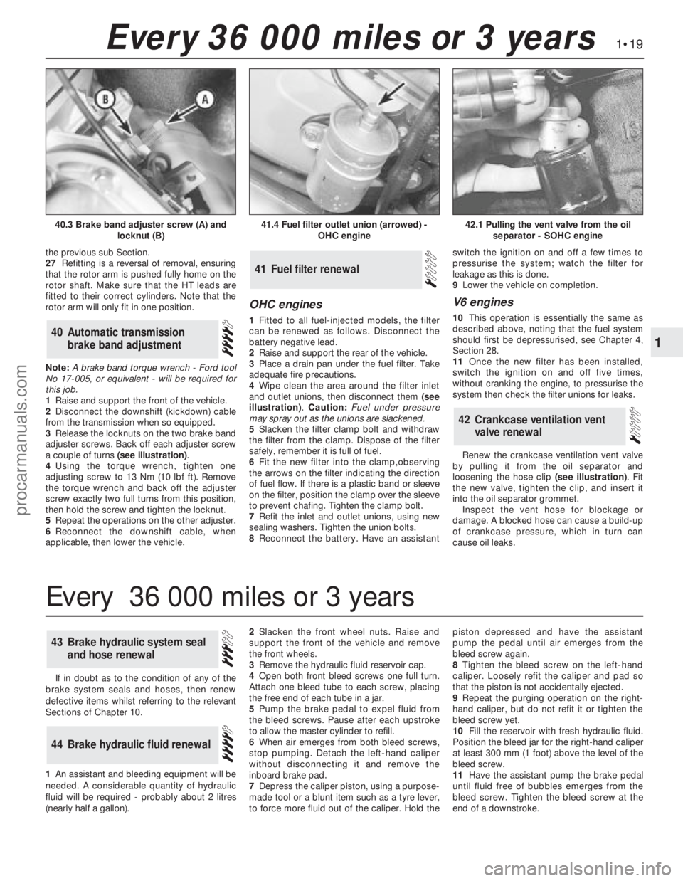
adjuster screws. Back off each adjuster screw
a couple of turns (see illustration).
4Using the torque wrench, tighten one
adjusting screw to 13 Nm (10 lbf ft). Remove
the torque wrench and back off the adjuster
screw exactly two full turns from this position,
then hold the screw and tighten the locknut.
5Repeat the operations on the other adjuster.
6Reconnect the downshift cable, when
applicable, then lower the vehicle.
OHC engines
1Fitted to all fuel-injected models, the filter
can be renewed as follows. Disconnect the
battery negative lead.
2Raise and support the rear of the vehicle.
3Place a drain pan under the fuel filter. Take
adequate fire precautions.
4Wipe clean the area around the filter inlet
and outlet unions, then disconnect them (see
illustration). Caution: Fuel under pressure
may spray out as the unions are slackened.
5Slacken the filter clamp bolt and withdraw
the filter from the clamp. Dispose of the filter
safely, remember it is full of fuel.
6Fit the new filter into the clamp,observing
the arrows on the filter indicating the direction
of fuel flow. If there is a plastic band or sleeve
on the filter, position the clamp over the sleeve
to prevent chafing. Tighten the clamp bolt.
7Refit the inlet and outlet unions, using new
sealing washers. Tighten the union bolts.
8Reconnect the battery. Have an assistantswitch the ignition on and off a few times to
pressurise the system; watch the filter for
leakage as this is done.
9Lower the vehicle on completion.
V6 engines
10This operation is essentially the same as
described above, noting that the fuel system
should first be depressurised, see Chapter 4,
Section 28.
11Once the new filter has been installed,
switch the ignition on and off five times,
without cranking the engine, to pressurise the
system then check the filter unions for leaks.
Renew the crankcase ventilation vent valve
by pulling it from the oil separator and
loosening the hose clip (see illustration). Fit
the new valve, tighten the clip, and insert it
into the oil separator grommet.
Inspect the vent hose for blockage or
damage. A blocked hose can cause a build-up
of crankcase pressure, which in turn can
cause oil leaks.
42Crankcase ventilation vent
valve renewal
41Fuel filter renewal
40Automatic transmission
brake band adjustment
1•19
1
Every 36 000 miles or 3 years
41.4 Fuel filter outlet union (arrowed) -
OHC engine42.1 Pulling the vent valve from the oil
separator - SOHC engine40.3 Brake band adjuster screw (A) and
locknut (B)
If in doubt as to the condition of any of the
brake system seals and hoses, then renew
defective items whilst referring to the relevant
Sections of Chapter 10.
1An assistant andbleeding equipment will be
needed. A considerable quantity of hydraulic
fluid will be required - probably about 2 litres
(nearly half a gallon).2Slacken the front wheel nuts. Raise and
support the front of the vehicle andremove
the front wheels.
3Remove the hydraulic fluid reservoir cap.
4Open both front bleed screws one full turn.
Attach one bleed tube to each screw, placing
the free end of each tube in a jar.
5Pump the brake pedal to expel fluid from
the bleed screws. Pause after each upstroke
to allow the master cylinder to refill.
6When air emerges from both bleed screws,
stop pumping. Detach the left-hand caliper
without disconnecting it and remove the
inboard brake pad.
7Depress the caliper piston, using a purpose-
made tool or a blunt item such as a tyre lever,
to force more fluid out of the caliper. Hold thepiston depressed and have the assistant
pump the pedal until air emerges from the
bleed screw again.
8Tighten the bleed screw on the left-hand
caliper. Loosely refit the caliper and pad so
that the piston is not accidentally ejected.
9Repeat the purging operation on the right-
hand caliper, but do not refit it or tighten the
bleed screw yet.
10Fill the reservoir with fresh hydraulic fluid.
Position the bleed jar for the right-hand caliper
at least 300 mm (1 foot) above the level of the
bleed screw.
11Have the assistant pump the brake pedal
until fluid free of bubbles emerges from the
bleed screw. Tighten the bleed screw at the
end of a downstroke.
44Brake hydraulic fluid renewal
43Brake hydraulic system seal
and hose renewal
Every 36 000 miles or 3 years
procarmanuals.com
Page 25 of 255
2A•2SOHCengines
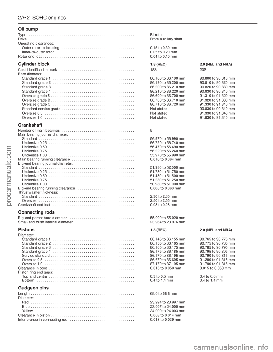
Oil pump
Type . . . . . . . . . . . . . . . . . . . . . . . . . . . . . . . . . . . . . . . . . . . . . . . . . . . .Bi-rotor
Drive . . . . . . . . . . . . . . . . . . . . . . . . . . . . . . . . . . . . . . . . . . . . . . . . . . . .From auxiliary shaft
Operating clearances:
Outer rotor-to-housing . . . . . . . . . . . . . . . . . . . . . . . . . . . . . . . . . . . .0.15 to 0.30 mm
Inner-to-outer rotor . . . . . . . . . . . . . . . . . . . . . . . . . . . . . . . . . . . . . . .0.05 to 0.20 mm
Rotor endfloat . . . . . . . . . . . . . . . . . . . . . . . . . . . . . . . . . . . . . . . . . . . . .0.04 to 0.10 mm
Cylinder block1.8 (REC)2.0 (NEL and NRA)
Cast identification mark . . . . . . . . . . . . . . . . . . . . . . . . . . . . . . . . . . . . .18S20S
Bore diameter:
Standard grade 1 . . . . . . . . . . . . . . . . . . . . . . . . . . . . . . . . . . . . . . . .86.180 to 86.190 mm90.800 to 90.810 mm
Standard grade 2 . . . . . . . . . . . . . . . . . . . . . . . . . . . . . . . . . . . . . . . .86.190 to 86.200 mm90.810 to 90.820 mm
Standard grade 3 . . . . . . . . . . . . . . . . . . . . . . . . . . . . . . . . . . . . . . . .86.200 to 86.210 mm90.820 to 90.830 mm
Standard grade 4 . . . . . . . . . . . . . . . . . . . . . . . . . . . . . . . . . . . . . . . .86.210 to 86.220 mm90.830 to 90.840 mm
Oversize grade 5 . . . . . . . . . . . . . . . . . . . . . . . . . . . . . . . . . . . . . . . . .86.690 to 86.700 mm91.310 to 91.320 mm
Oversize grade B . . . . . . . . . . . . . . . . . . . . . . . . . . . . . . . . . . . . . . . . .86.700 to 86.710 mm91.320 to 91.330 mm
Oversize grade C . . . . . . . . . . . . . . . . . . . . . . . . . . . . . . . . . . . . . . . .86.710 to 86.720 mm91.330 to 91.340 mm
Standard service grade . . . . . . . . . . . . . . . . . . . . . . . . . . . . . . . . . . . .Not stated90.830 to 90.840 mm
Oversize 0.5 . . . . . . . . . . . . . . . . . . . . . . . . . . . . . . . . . . . . . . . . . . . .Not stated91.330 to 91.340 mm
Oversize 1.0 . . . . . . . . . . . . . . . . . . . . . . . . . . . . . . . . . . . . . . . . . . . .Not stated91.830 to 91.840 mm
Crankshaft
Number of main bearings . . . . . . . . . . . . . . . . . . . . . . . . . . . . . . . . . . . .5
Main bearing journal diameter:
Standard . . . . . . . . . . . . . . . . . . . . . . . . . . . . . . . . . . . . . . . . . . . . . . .56.970 to 56.990 mm
Undersize 0.25 . . . . . . . . . . . . . . . . . . . . . . . . . . . . . . . . . . . . . . . . . .56.720 to 56.740 mm
Undersize 0.50 . . . . . . . . . . . . . . . . . . . . . . . . . . . . . . . . . . . . . . . . . .56.470 to 56.490 mm
Undersize 0.75 . . . . . . . . . . . . . . . . . . . . . . . . . . . . . . . . . . . . . . . . . .56.220 to 56.240 mm
Undersize 1.00 . . . . . . . . . . . . . . . . . . . . . . . . . . . . . . . . . . . . . . . . . .55.970 to 55.990 mm
Main bearing running clearance . . . . . . . . . . . . . . . . . . . . . . . . . . . . . . .0.010 to 0.064 mm
Big-end bearing journal diameter:
Standard . . . . . . . . . . . . . . . . . . . . . . . . . . . . . . . . . . . . . . . . . . . . . . .51.980 to 52.000 mm
Undersize 0.25 . . . . . . . . . . . . . . . . . . . . . . . . . . . . . . . . . . . . . . . . . .51.730 to 51.750 mm
Undersize 0.50 . . . . . . . . . . . . . . . . . . . . . . . . . . . . . . . . . . . . . . . . . .51.480 to 51.500 mm
Undersize 0.75 . . . . . . . . . . . . . . . . . . . . . . . . . . . . . . . . . . . . . . . . . .51.230 to 51.250 mm
Undersize 1.00 . . . . . . . . . . . . . . . . . . . . . . . . . . . . . . . . . . . . . . . . . .50.980 to 51.000 mm
Big-end bearing running clearance . . . . . . . . . . . . . . . . . . . . . . . . . . . .0.006 to 0.060 mm
Thrustwasher thickness:
Standard . . . . . . . . . . . . . . . . . . . . . . . . . . . . . . . . . . . . . . . . . . . . . . .2.30 to 2.35 mm
Oversize . . . . . . . . . . . . . . . . . . . . . . . . . . . . . . . . . . . . . . . . . . . . . . .2.50 to 2.55 mm
Crankshaft endfloat . . . . . . . . . . . . . . . . . . . . . . . . . . . . . . . . . . . . . . . .0.08 to 0.28 mm
Connecting rods
Big-end parent bore diameter . . . . . . . . . . . . . . . . . . . . . . . . . . . . . . . .55.000 to 55.020 mm
Small-end bush internal diameter . . . . . . . . . . . . . . . . . . . . . . . . . . . . . .23.964 to 23.976 mm
Pistons1.8 (REC)2.0 (NEL and NRA)
Diameter:
Standard grade 1 . . . . . . . . . . . . . . . . . . . . . . . . . . . . . . . . . . . . . . . .86.145 to 86.155 mm90.765 to 90.775 mm
Standard grade 2 . . . . . . . . . . . . . . . . . . . . . . . . . . . . . . . . . . . . . . . .86.155 to 86.165 mm90.775 to 90.785 mm
Standard grade 3 . . . . . . . . . . . . . . . . . . . . . . . . . . . . . . . . . . . . . . . .86.165 to 86.175 mm90.785 to 90.795 mm
Standard grade 4 . . . . . . . . . . . . . . . . . . . . . . . . . . . . . . . . . . . . . . . .86.175 to 86.185 mm90.795 to 90.805 mm
Service standard . . . . . . . . . . . . . . . . . . . . . . . . . . . . . . . . . . . . . . . . .86.170 to 86.195 mm90.790 to 90.815 mm
Oversize 0.5 . . . . . . . . . . . . . . . . . . . . . . . . . . . . . . . . . . . . . . . . . . . .86.670 to 86.695 mm91.290 to 91.315 mm
Oversize 1.0 . . . . . . . . . . . . . . . . . . . . . . . . . . . . . . . . . . . . . . . . . . . .87.170 to 87.195 mm91.790 to 91.815 mm
Clearance in bore . . . . . . . . . . . . . . . . . . . . . . . . . . . . . . . . . . . . . . . . . .0.015 to 0.050 mm0.015 to 0.050 mm
Piston ring end gaps:
Top and centre . . . . . . . . . . . . . . . . . . . . . . . . . . . . . . . . . . . . . . . . . .0.3 to 0.5 mm0.4 to 0.6 mm
Bottom . . . . . . . . . . . . . . . . . . . . . . . . . . . . . . . . . . . . . . . . . . . . . . . .0.4 to 1.4 mm0.4 to 1.4 mm
Gudgeon pins
Length . . . . . . . . . . . . . . . . . . . . . . . . . . . . . . . . . . . . . . . . . . . . . . . . . . .68.0 to 68.8 mm
Diameter:
Red . . . . . . . . . . . . . . . . . . . . . . . . . . . . . . . . . . . . . . . . . . . . . . . . . . .23.994 to 23.997 mm
Blue . . . . . . . . . . . . . . . . . . . . . . . . . . . . . . . . . . . . . . . . . . . . . . . . . . .23.997 to 24.000 mm
Yellow . . . . . . . . . . . . . . . . . . . . . . . . . . . . . . . . . . . . . . . . . . . . . . . . .24.000 to 24.003 mm
Clearance in piston . . . . . . . . . . . . . . . . . . . . . . . . . . . . . . . . . . . . . . . . .0.008 to 0.014 mm
Interference in connecting rod . . . . . . . . . . . . . . . . . . . . . . . . . . . . . . . .0.018 to 0.039 mm
procarmanuals.com
Page 27 of 255
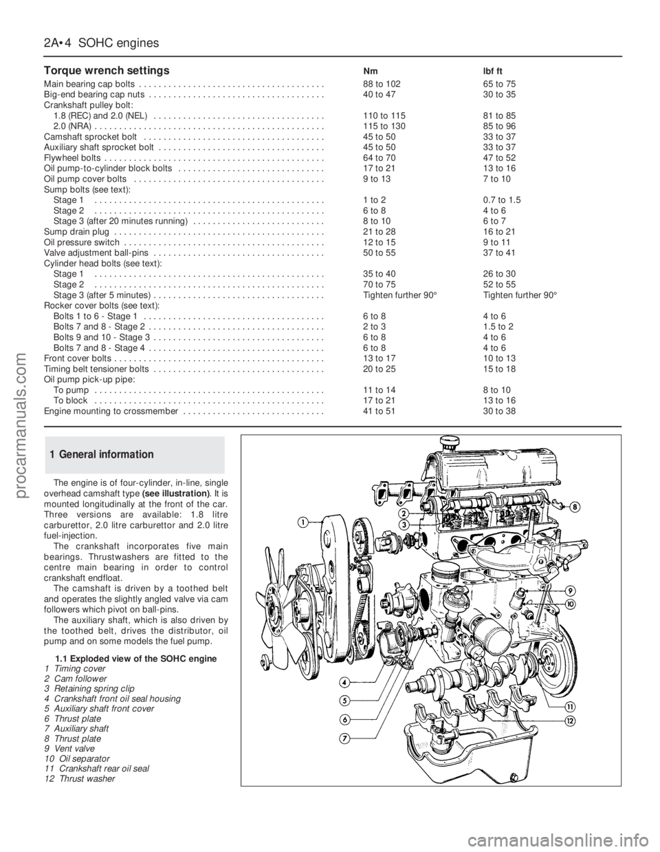
The engine is of four-cylinder, in-line, single
overhead camshaft type (see illustration). It is
mounted longitudinally at the front of the car.
Three versions are available: 1.8 litre
carburettor, 2.0 litre carburettor and 2.0 litre
fuel-injection.
The crankshaft incorporates five main
bearings. Thrustwashers are fitted to the
centre main bearing in order to control
crankshaft endfloat.
The camshaft is driven by a toothed belt
and operates the slightly angled valve via cam
followers which pivot on ball-pins.
The auxiliary shaft, which is also driven by
the toothed belt, drivesthe distributor, oil
pump and on some models the fuel pump.
1General information
2A•4SOHCengines
Torque wrench settingsNmlbf ft
Main bearing cap bolts . . . . . . . . . . . . . . . . . . . . . . . . . . . . . . . . . . . . . .88 to 10265 to 75
Big-end bearing cap nuts . . . . . . . . . . . . . . . . . . . . . . . . . . . . . . . . . . . .40 to 4730 to 35
Crankshaft pulley bolt:
1.8 (REC) and 2.0 (NEL) . . . . . . . . . . . . . . . . . . . . . . . . . . . . . . . . . . .110 to 11581 to 85
2.0 (NRA) . . . . . . . . . . . . . . . . . . . . . . . . . . . . . . . . . . . . . . . . . . . . . . .115 to 13085 to 96
Camshaft sprocket bolt . . . . . . . . . . . . . . . . . . . . . . . . . . . . . . . . . . . . .45 to 5033 to 37
Auxiliary shaft sprocket bolt . . . . . . . . . . . . . . . . . . . . . . . . . . . . . . . . . .45 to 5033 to 37
Flywheel bolts . . . . . . . . . . . . . . . . . . . . . . . . . . . . . . . . . . . . . . . . . . . . .64 to 7047 to 52
Oil pump-to-cylinder block bolts . . . . . . . . . . . . . . . . . . . . . . . . . . . . . .17 to 2113 to 16
Oil pump cover bolts . . . . . . . . . . . . . . . . . . . . . . . . . . . . . . . . . . . . . . .9 to 137 to 10
Sump bolts (see text):
Stage 1 . . . . . . . . . . . . . . . . . . . . . . . . . . . . . . . . . . . . . . . . . . . . . . .1 to 20.7 to 1.5
Stage 2 . . . . . . . . . . . . . . . . . . . . . . . . . . . . . . . . . . . . . . . . . . . . . . .6 to 84 to 6
Stage 3 (after 20 minutes running) . . . . . . . . . . . . . . . . . . . . . . . . . . .8 to 106 to 7
Sump drain plug . . . . . . . . . . . . . . . . . . . . . . . . . . . . . . . . . . . . . . . . . . .21 to 2816 to 21
Oil pressure switch . . . . . . . . . . . . . . . . . . . . . . . . . . . . . . . . . . . . . . . . .12 to 159 to 11
Valve adjustment ball-pins . . . . . . . . . . . . . . . . . . . . . . . . . . . . . . . . . . .50 to 5537 to 41
Cylinder head bolts (see text):
Stage 1 . . . . . . . . . . . . . . . . . . . . . . . . . . . . . . . . . . . . . . . . . . . . . . .35 to 4026 to 30
Stage 2 . . . . . . . . . . . . . . . . . . . . . . . . . . . . . . . . . . . . . . . . . . . . . . .70 to 7552 to 55
Stage 3 (after 5 minutes) . . . . . . . . . . . . . . . . . . . . . . . . . . . . . . . . . . .Tighten further 90°Tighten further 90°
Rocker cover bolts (see text):
Bolts 1 to 6 - Stage 1 . . . . . . . . . . . . . . . . . . . . . . . . . . . . . . . . . . . . .6 to 84 to 6
Bolts 7 and 8 - Stage 2 . . . . . . . . . . . . . . . . . . . . . . . . . . . . . . . . . . . .2 to 31.5 to 2
Bolts 9 and 10 - Stage 3 . . . . . . . . . . . . . . . . . . . . . . . . . . . . . . . . . . .6 to 84 to 6
Bolts 7 and 8 - Stage 4 . . . . . . . . . . . . . . . . . . . . . . . . . . . . . . . . . . . .6 to 84 to 6
Front cover bolts . . . . . . . . . . . . . . . . . . . . . . . . . . . . . . . . . . . . . . . . . . .13 to 1710 to 13
Timing belt tensioner bolts . . . . . . . . . . . . . . . . . . . . . . . . . . . . . . . . . . .20 to 2515 to 18
Oil pump pick-up pipe:
To pump . . . . . . . . . . . . . . . . . . . . . . . . . . . . . . . . . . . . . . . . . . . . . . .11 to 148 to 10
To block . . . . . . . . . . . . . . . . . . . . . . . . . . . . . . . . . . . . . . . . . . . . . . .17 to 2113 to 16
Engine mounting to crossmember . . . . . . . . . . . . . . . . . . . . . . . . . . . . .41 to 5130 to 38
1.1 Exploded view of the SOHC engine
1 Timing cover
2 Cam follower
3 Retaining spring clip
4 Crankshaft front oil seal housing
5 Auxiliary shaft front cover
6 Thrust plate
7 Auxiliary shaft
8 Thrust plate
9 Vent valve
10 Oil separator
11 Crankshaft rear oil seal
12 Thrust washer
procarmanuals.com
Page 29 of 255
14Take the weight of the engine and remove
the two engine bearer-to-mounting nuts.
15Lift the engine/transmission, at the same
time lowering the trolley jack. Draw the unit
forwards and lift it out of the engine bay.
16Temporarily refit the anti-roll bar if the
vehicle is to be moved.
1With the engine and gearbox on the bench,
remove the starter motor.
2Remove the bolt from the engine adapter plate.
3Remove the bracing strap and the
remaining engine-to-bellhousing bolts.
4With the aid of an assistant draw the
gearbox off the engine. Do not allow the weight
of the gearbox to hang on the input shaft.
1It is best to mount the engine on a
dismantling stand, but if this is not available,
stand the engine on a strong bench at a
comfortable working height. Failing this, it will
have to be stripped down on the floor.
2Cleanliness is most important, and if the
engine is dirty, it should be cleaned with
paraffin while keeping it in an upright position.
3Avoid working with the engine on a concrete
floor, as grit can be a real source of trouble.
4As parts are removed, clean them in paraffin.
However, do not immerse parts with internal
oilways in paraffin as it is difficult to remove,
usually requiring a high pressure hose.
5It is advisable to have suitable containers to
hold small items according to their use, as this
will help when reassembling the engine and
also prevent possible losses.
6Always obtain complete sets of gaskets
when the engine is being dismantled, but
retain the old gaskets with a view of using
them as a pattern to make a replacement if a
new one is not available.7When possible, refit nuts, bolts and washers
in their location after being removed, as this
helps protect the threads and will also be
helpful when reassembling the engine.
8Retain unserviceable components in order
to compare them with the new parts supplied.
9A Torx key, size T55, will be needed for
dealing with the cylinder head bolts. A 12-
spline key (to fit bolt size M8) will be needed
for the oil pump bolts. Other Torx and 12-
spline bolts may be encountered; sets of the
keys required to deal with them are available
from most motor accessory shops and tool
factors.
10Another tool which is useful, though by no
means essential, is a valve spring compressor
of the type which hooks under the camshaft
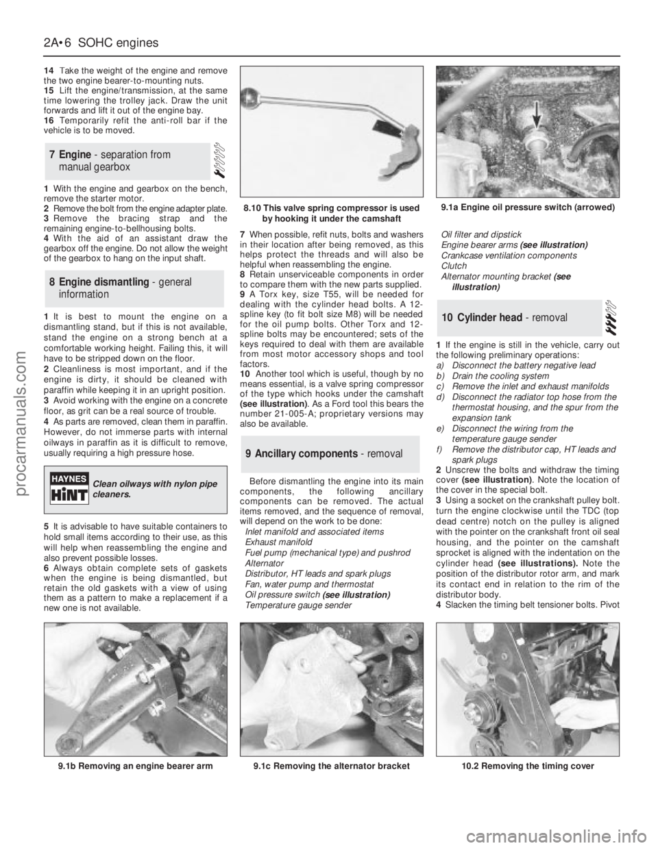
(see illustration). As a Ford tool this bears the
number 21-005-A; proprietary versions may
also be available.
Before dismantling the engine into its main
components, the following ancillary
components can be removed. The actual
items removed, and the sequence of removal,
will depend on the work to be done:
Inlet manifold and associated items
Exhaust manifold
Fuel pump (mechanical type) and pushrod
Alternator
Distributor, HT leads and spark plugs
Fan, water pump and thermostat
Oil pressure switch
(see illustration)
Temperature gauge senderOil filter and dipstick
Engine bearer arms (see illustration)
Crankcase ventilation components
Clutch
Alternator mounting bracket (see
illustration)
1If the engine is still in the vehicle, carry out
the following preliminary operations:
a)Disconnect the battery negative lead
b)Drain the cooling system
c)Remove the inlet and exhaust manifolds
d)Disconnect the radiator top hose from the
thermostat housing, and the spur from the
expansion tank
e)Disconnect the wiring from the
temperature gauge sender
f)Remove the distributor cap, HT leads and
spark plugs
2Unscrew the bolts and withdraw the timing
cover (see illustration). Note the location of
the cover in the special bolt.
3Using a socket on the crankshaft pulley bolt.
turn the engine clockwise until the TDC (top
dead centre) notch on the pulley is aligned
with the pointer on the crankshaft front oil seal
housing, and the pointer on the camshaft
sprocket is aligned with the indentation on the
cylinder head (see illustrations).Note the
position of the distributor rotor arm, and mark
its contact end in relation to the rim of the
distributor body.
4Slacken the timing belt tensioner bolts. Pivot
10Cylinder head - removal
9Ancillary components - removal
8Engine dismantling - general
information
7Engine - separation from
manual gearbox
2A•6SOHCengines
9.1a Engine oil pressure switch (arrowed)
9.1b Removing an engine bearer arm9.1c Removing the alternator bracket
8.10 This valve spring compressor is used
by hooking it under the camshaft
Clean oilways with nylon pipe
cleaners.
10.2 Removing the timing cover
procarmanuals.com
Page 31 of 255
1Remove the camshaft as described in the
previous Section. (If tool 21-005-A is available,
leave the camshaft in place until the valves
have been removed).
2Using a valve spring compressor, compress
each valve spring in turn until the split collets
can be removed. Release the compressor and
remove the cap and spring, keeping them
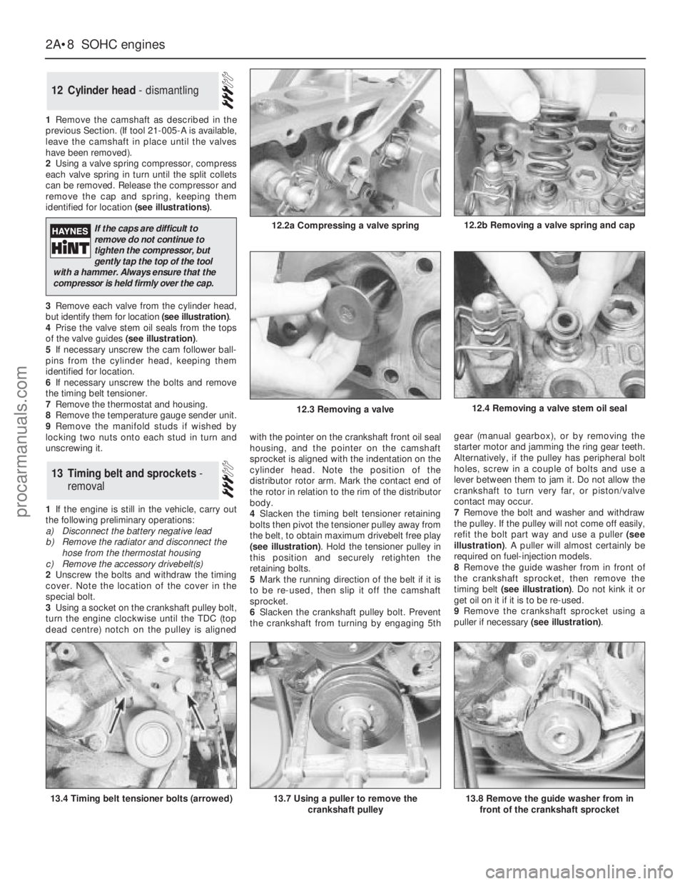
identified for location (see illustrations).
3Remove each valve from the cylinder head,
but identify them for location (see illustration).
4Prise the valve stem oil seals from the tops
of the valve guides (see illustration).
5If necessary unscrew the cam follower ball-
pins from the cylinder head, keeping them
identified for location.
6If necessary unscrew the bolts and remove
the timing belt tensioner.
7Remove the thermostat and housing.
8Remove the temperature gauge sender unit.
9Remove the manifold studs if wished by
locking two nuts onto each stud in turn and
unscrewing it.
1If the engine is still in the vehicle, carry out
the following preliminary operations:
a)Disconnect the battery negative lead
b)Remove the radiator and disconnect the
hose from the thermostat housing
c)Remove the accessory drivebelt(s)
2Unscrew the bolts and withdraw the timing
cover. Note the location of the cover in the
special bolt.
3Using a socket on the crankshaft pulley bolt,
turn the engine clockwise until the TDC (top
dead centre) notch on the pulley is alignedwith the pointer on the crankshaft front oil seal
housing, and the pointer on the camshaft
sprocket is aligned with the indentation on the
cylinder head. Note the position of the
distributor rotor arm. Mark the contact end of
the rotor in relation to the rim of the distributor
body.
4Slacken the timing belt tensioner retaining
bolts then pivot the tensioner pulley away from
the belt, to obtain maximum drivebelt free play
(see illustration). Hold the tensioner pulley in
this position and securely retighten the
retaining bolts.
5Mark the running direction of the belt if it is
to be re-used, then slip it off the camshaft
sprocket.
6Slacken the crankshaft pulley bolt. Prevent
the crankshaft from turning by engaging 5thgear (manual gearbox), or by removing the
starter motor and jamming the ring gear teeth.
Alternatively, if the pulley has peripheral bolt
holes, screw in a couple of bolts and use a
lever between them to jam it. Do not allow the
crankshaft to turn very far, or piston/valve
contact may occur.
7Remove the bolt and washer and withdraw
the pulley. If the pulley will not come off easily,
refit the bolt part way and use a puller (see
illustration). A puller will almost certainly be
required on fuel-injection models.
8Remove the guide washer from in front of
the crankshaft sprocket, then remove the
timing belt (see illustration). Do not kink it or
get oil on it if it is to be re-used.
9Remove the crankshaft sprocket using a
puller if necessary (see illustration).
13Timing belt and sprockets -
removal
12Cylinder head - dismantling
2A•8SOHCengines
12.2a Compressing a valve spring
13.4 Timing belt tensioner bolts (arrowed)13.7 Using a puller to remove the
crankshaft pulley
12.4 Removing a valve stem oil seal
13.8 Remove the guide washer from in
front of the crankshaft sprocket
12.2b Removing a valve spring and cap
12.3 Removing a valve
If the caps are difficult to
remove do not continue to
tighten the compressor, but
gently tap the top of the tool
with a hammer. Always ensure that the
compressor is held firmly over the cap.
procarmanuals.com
Page 34 of 255
See Chapter 1, Section 8.
1Remove the sump and cylinder head.
2Check the big-end caps for identification
marks and if necessary use a centre-punch to
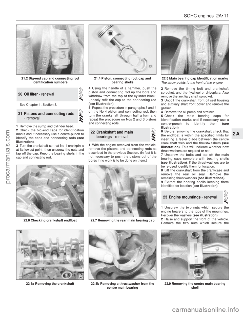
identify the caps and connecting rods (see
illustration).
3Turn the crankshaft so that No 1 crankpin is
at its lowest point, then unscrew the nuts and
tap off the cap. Keep the bearing shells in the
cap and connecting rod.4Using the handle of a hammer, push the
piston and connecting rod up the bore and
withdraw from the top of the cylinder block.
Loosely refit the cap to the connecting rod
(see illustration).
5Repeat the procedure in paragraphs 3 and 4
on the No 4 piston and connecting rod, then
turn the crankshaft through half a turn and
repeat the procedure on Nos 2 and 3 pistons
and connecting rods.
1With the engine removed from the vehicle,
remove the pistons and connecting rods as
described in the previous Section. (In fact it is
not necessary to push the pistons out of the
bores if no work is to be done on them.)2Remove the timing belt and crankshaft
sprocket, and the flywheel or driveplate. Also
remove the auxiliary shaft sprocket.
3Unbolt the crankshaft front oil seal housing
and auxiliary shaft front cover and remove the
gasket.
4Remove the oil pump and strainer.
5Check the main bearing caps for
identification marks and if necessary use a
centre-punch to identify them (see
illustration).
6Before removing the crankshaft check that
the endfloat is within the specified limits by
inserting a feeler blade between the centre
crankshaft web and the thrustwashers (see
illustration). This will indicate whether new
thrustwashers are required or not.
7Unscrew the bolts and tap off the main
bearing caps complete with bearing shells
(see illustration). If the thrustwashers are to
be re-used identify them for location.
8Lift the crankshaft from the crankcase and
remove the rear oil seal. Remove the
remaining thrustwashers (see illustrations).
9Extract the bearing shells keeping them
identified for location (see illustration).
1Unscrew the two nuts which secure the
engine bearers to the tops of the mountings.
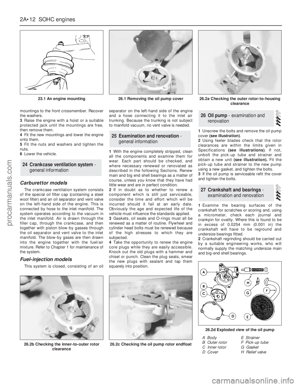
Recover the washers(see illustration).
2Raise and support the front of the vehicle.
Remove the two nuts which secure the
23Engine mountings - renewal
22Crankshaft and main
bearings - removal
21Pistons and connecting rods
- removal
20Oil filter - renewal
SOHCengines 2A•11
2A
21.2 Big-end cap and connecting rod
identification numbers21.4 Piston, connecting rod, cap and
bearing shells22.5 Main bearing cap identification marks
The arrow points to the front of the engine
22.8a Removing the crankshaft
22.6 Checking crankshaft endfloat
22.8b Removing a thrustwasher from the
centre main bearing
22.7 Removing the rear main bearing cap
22.9 Removing the centre main bearing
shell
procarmanuals.com
Page 35 of 255
mountings to the front crossmember. Recover
the washers.
3Raise the engine with a hoist or a suitable
protected jack until the mountings are free,
then remove them.
4Fit the new mountings and lower the engine
onto them.
5Fit the nuts and washers and tighten the
nuts.
6Lower the vehicle.
Carburettor models
The crankcase ventilation system consists
of the special oil filter cap (containing a steel
wool filter) and an oil separator and vent valve
on the left-hand side of the engine. This is
connected by hose to the inlet manifold. The
system operates according to the vacuum in
the inlet manifold. Air is drawn through the
filler cap, through the crankcase, and then
together with piston blow-by gasses through
the oil separator and vent valve to the inlet
manifold. The blow-by gases are then drawn
into the engine together with the fuel/air
mixture. Refer to Chapter 1 for maintenance of
the system.
Fuel-injection models
This system is closed, consisting of an oilseparator on the left-hand side of the engine
and a hose connecting it to the inlet air
trunking. Because the trunking is not subject
to manifold vacuum, no vent valve is needed.
1With the engine completely stripped, clean
all the components and examine them for
wear. Each part should be checked, and
where necessary renewed or renovated as
described in the following Sections. Renew
main and big end shell bearings as a matter of
course, unless you know that they have had
little wear and are in perfect condition.
2If in doubt as to whether to renew a
component which is still just serviceable,
consider the time and effort which will be
incurred should it fail at an early date.
Obviously the age and expected life of the
vehicle must influence the standards applied.
3Gaskets, oil seals and O-rings must all be
renewed as a matter of routine. Flywheel and
cylinder head bolts must be renewed because
of the high stresses to which they are
subjected.
4Take the opportunity to renew the engine
core plugs while they are easily accessible.
Knock out the old plugs with a hammer and
chisel or punch. Clean the plug seats, smear
the new plugs with sealant and tap them
squarely into position.1Unscrew the bolts and remove the oil pump
cover (see illustration).
2Using feeler blades check that the rotor
clearances are within the limits given in
Specifications (see illustrations). If not,
unbolt the pick-up tube and strainer and
obtain a new unit (see illustration).Fit the
pick-up tube and strainer to the new pump
using a new gasket, and tighten the bolts.
3If the oil pump is serviceable refit the cover
and tighten the bolts.
1Examine the bearing surfaces of the
crankshaft for scratches or scoring and, using
a micrometer, check each journal and
crankpin for ovality. Where this is found to be
in excess of 0.0254 mm (0.001 in) the
crankshaft will have to be reground and
undersize bearings fitted.
2Crankshaft regrinding should be carried out
by a suitable engineering works, who will
normally supply the matching undersize main
and big-end shell bearings.
27Crankshaft and bearings -
examination and renovation
26Oil pump - examination and
renovation
25Examination and renovation -
general information
24Crankcase ventilation system -
general information
2A•12SOHCengines
23.1 An engine mounting
26.2b Checking the inner-to-outer rotor
clearance26.2c Checking the oil pump rotor endfloat
26.2d Exploded view of the oil pump
A Body
B Outer rotor
C Inner rotor
D CoverE Strainer
F Pick-up tube
G Gasket
H Relief valve
26.1 Removing the oil pump cover26.2a Checking the outer rotor-to-housing
clearance
procarmanuals.com