1985 FORD GRANADA washer
[x] Cancel search: washerPage 152 of 255
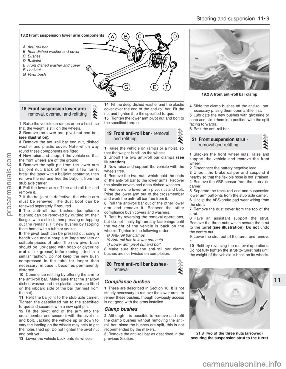
1Raise the vehicle on ramps or on a hoist, so
that the weight is still on the wheels.
2Remove the lower arm pivot nut and bolt
(see illustration).
3Remove the anti-roll bar end nut, dished
washer and plastic cover. Note which way
round these components are fitted.
4Now raise and support the vehicle so that
the front wheels are off the ground.
5Remove the split pin from the lower arm
balljoint nut. Back off the nut a few turns,
break the taper with a balljoint separator, then
remove the nut and free the balljoint from the
stub axle carrier.
6Pull the lower arm off the anti-roll bar and
remove it.
7If the balljoint is defective, the whole arm
must be renewed. The dust boot can be
renewed separately if required.
8The anti-roll bar bushes (compliance
bushes) can be removed by cutting off their
flanges with a chisel, then pressing or tapping
out the remains. Fit new bushes by tapping
them home with a tube or socket.
9The pivot bush can be pressed out using a
bench vice and a couple of large sockets or
suitable pieces of tube. The new pivot bush
should be lubricated with soap or glycerine
(notoil or grease) before being fitted in a
similar fashion. Do not keep the new bush
compressed in the tube for longer than
necessary, in case it becomes permanently
distorted.
10Commence refitting by offering the arm to
the anti-roll bar. Make sure that the shallow
dished washer and the plastic cover are fitted
on the inboard side of the bar (furthest from
the nut).
11Refit the balljoint to the stub axle carrier.
Tighten the castellated nut to the specified
torque and secure it with a new split pin.
12Fit the pivot end of the arm into the
crossmember and secure it with the pivot nut
and bolt. Jacking the vehicle up or down to
vary the loading on the wheels may help to get
the holes lined up. Do not tighten the pivot nut
and bolt yet.
13Lower the vehicle back onto its wheels.14Fit the deep dished washer and the plastic
cover over the end of the anti-roll bar. Fit the
nut and tighten it to the specified torque.
15Tighten the lower arm pivot nut and bolt to
the specified torque.
1Raise the vehicle on ramps or a hoist, so
that the weight is still on the wheels.
2Unbolt the two anti-roll bar clamps (see
illustration).
3Now raise and support the vehicle with the
wheels free.
4Remove the two nuts which hold the ends
of the anti-roll bar to the lower arms. Recover
the plastic covers and deep dished washers.
5Remove one lower arm pivot nut and bolt.
Prise the lower arm out of the crossmember
and work the anti-roll bar free from it.
6Pull the anti-roll bar out of the other lower
arm and remove it. Recover the other
compliance bush covers and washers.
7Refit by reversing the removal operations,
but do not finally tighten any fastenings until
the weight of the vehicle is back on the
wheels. Tighten in the following order:
a)Anti-roll bar clamps
b)Anti-roll bar-to lower arm nuts
c)Lower arm pivot nut and bolt
8Make sure that the anti-roll bar clamp
bushes are not twisted on completion.
Compliance bushes
1These are described in Section 18. It is not
strictly necessary to remove the lower arms to
renew these bushes, though obviously access
is not good with the arms installed.
Clamp bushes
2Although it is possible to remove and refit
the clamp bushes without removing the anti-
roll bar, since the bushes are split, this is not
recommended by the makers.
3Remove the anti-roll bar as described in the
previous Section.4Slide the clamp bushes off the anti-roll bar,
if necessary prising them open a little first.
5Lubricate the new bushes with glycerine or
soap and slide them into position with the split
facing forwards.
6Refit the anti-roll bar.
1Slacken the front wheel nuts, raise and
support the vehicle and remove the front
wheel.
2Disconnect the battery negative lead.
3Unbolt the brake caliper and suspend it
nearby so that the flexible hose is not strained.
4Remove the ABS sensor from the stub axle
carrier.
5Separate the track rod end and suspension
lower arm balljoints from the stub axle carrier.
6Unclip the ABS/brake pad wear wiring from
the strut.
7Remove the dust cover from the top of the
strut.
8Have an assistant support the strut.
Remove the three nuts which secure the strut
to the turret (see illustration).Do notundo
the centre nut.
9Lower the strut out of the turret and remove
it.
10Refit by reversing the removal operations.
Do not fully tighten the strut-to-turret nuts until
the weight of the vehicle is back on its wheels.
21Front suspension strut -
removal and refitting
20Front anti-roll bar bushes -
renewal
19Front anti-roll bar - removal
and refitting
18Front suspension lower arm -
removal, overhaul and refitting
Steering and suspension 11•9
11
19.2 A front anti-roll bar clamp
21.8 Two of the three nuts (arrowed)
securing the suspension strut to the turret
18.2 Front suspension lower arm components
A Anti-roll bar
B Rear dished washer and cover
C Bushes
D Balljoint
E Front dished washer and cover
F Locknut
G Pivot bush
procarmanuals.com
Page 153 of 255
1With the strut removed, clamp it in a vice
with protected jaws.2Remove the stub axle carrier pinch-bolts.
Spread the carrier by carefully introducing a
chisel or blunt screwdriver into the crack, then
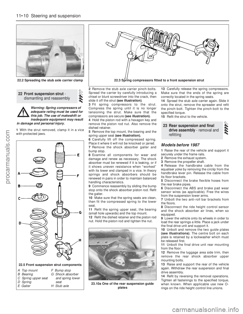
slide it off the strut (see illustration).
3Fit spring compressors to the strut.
Compress the spring until it is no longer
tensioning the strut. Make sure that the
compressors are secure (see illustration).
4Hold the piston rod with a hexagon key and
remove the piston rod nut. Also remove the
dished retainer.
5Remove the top mount, the bearing and the
spring upper seat(see illustration).
6Carefully lift off the compressed spring.
Place it where it will not be knocked or jarred.
7Remove the shock absorber gaiter and
bump stop.
8Examine all components for wear and
damage and renew as necessary. The shock
absorber must be renewed if it is leaking, or if
it shows uneven resistance when “worked”
with its lower end clamped in a vice. In theory
springs and shock absorbers should be
renewed in pairs in order to maintain balanced
handling characteristics.
9Commence reassembly by sliding the bump
stop onto the shock absorber piston rod. Refit
the gaiter.
10Make sure that the spring seats are clean,
then fit the compressed spring to the lower
seat.
11Refit the spring upper seat, the bearing
(small hole upwards) and the top mount.
12Refit the dished retainer and the piston rod
nut. Hold the piston rod and tighten the nut.13Carefully release the spring compressors.
Make sure that the ends of the spring are
correctly located in the spring seats.
14Spread the stub axle carrier again. Slide it
onto the strut, remove the spreader and refit
the pinch-bolt. Tighten the pinch-bolt to the
specified torque.
15Refit the strut to the vehicle.
Models before 1987
1Raise the rear of the vehicle and support it
securely under the frame rails.
2Remove the exhaust system.
3Remove the propeller shaft.
4Release the handbrake cable from the
equaliser yoke by removing the circlip from the
handbrake lever pin. Release the cable from
its floor brackets.
5Disconnect the brake flexible hoses from
the rear brake pipes.
6Disconnect the ABS and brake pad wear
sensor wires (as applicable). Free the wires
from the suspension lower arms.
7Unbolt the two anti-roll bar brackets from
the floors.
8Disconnect the ride height control sensor
and the shock absorber air lines, when so
equipped.
9Lower the vehicle onto its wheels in order to
load the rear springs a little. Place a jack under
the final drive unit and support it.
10Unbolt and remove the two guide plates
(see illustrations). The centre bolt on each
plate is retained by a lockwasher which must
be released first.
11Unbolt the final drive unit rear mounting
from the floor.
12Remove the luggage area side trim, then
remove the rear shock absorber upper
mounting bolts.
13Raise and support the rear of the vehicle
again. Withdraw the rear suspension and final
drive assembly.
14Refit by reversing the removal operations.
Tighten all fastenings to the specified torque,
when known. When applicable use new O-
rings on the ride height control line unions.
23Rear suspension and final
drive assembly - removal and
refitting
22Front suspension strut -
dismantling and reassembly
11•10Steering and suspension
22.2 Spreading the stub axle carrier clamp22.3 Spring compressors fitted to a front suspension strut
22.5 Front suspension strut components
A Top mount
B Bearing
C Spring upper seat
D Spring
E GaiterF Bump stop
G Shock absorber
and spring lower
seat
H Stub axle
Warning: Spring compressors of
adequate rating must be used for
this job. The use of makeshift or
inadequate equipment may result
in damage and personal injury.
23.10a One of the rear suspension guide
plates
procarmanuals.com
Page 154 of 255
15Bleed the brake hydraulic system and
adjust the handbrake on completion.
Models from 1987
16From 1987, the tab washer which secures
the guide plate centre bolt on each side has
been deleted. A self-locking bolt and plain
washer are used instead.
17The new bolt and washer should be fitted
to earlier models if the old bolt has been
removed for any reason. The tab washer
should be discarded.
18The tightening torque for the new bolt
remains the same as that given for the original.
1Remove the wheel trim. Apply the
handbrake and chock the front wheels.
2Slacken the driveshaft stub axle. This nut is
very tight. The left-hand nut has aleft-hand
thread, therefore it is undone clockwise.
3Remove the brake disc.
4Remove the driveshaft stub axle.
5Remove the four bolts which secure the
hub. Pull the hub off the driveshaft stub,
leaving the disc splash shield loose.
6Refit by reversing the removal operations.
Carry out the final tightening of the driveshaft
stub nut with the wheels on the ground.
1Remove the rear hub as described in the
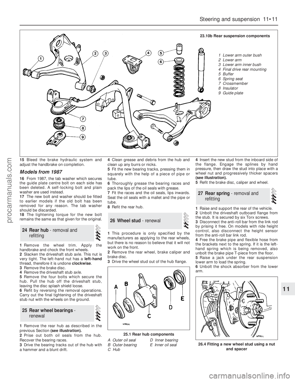
previous Section (see illustration).
2Prise out both oil seals from the hub.
Recover the bearing races.
3Drive the bearing tracks out of the hub with
a hammer and a blunt drift.4Clean grease and debris from the hub and
clean up any burrs or nicks.
5Fit the new bearing tracks, pressing them in
squarely with the help of a piece of pipe or
tube.
6Thoroughly grease the bearing races and
pack the lips of the oil seals with grease.
7Fit the races and the oil seals, lips inwards.
Seat the oil seals with a mallet and the pipe or
tube.
8Refit the rear hub.
1This procedure is only specified by the
manufacturers as applying to the rear wheels,
but there is no reason to believe that it will not
work on the front.
2Remove the rear wheel, brake caliper and
brake disc.
3Drive the wheel stud out of the hub flange. 4Insert the new stud from the inboard side of
the flange. Engage the splines by hand
pressure, then draw the stud into place with a
wheel nut and progressively thicker spacers
(see illustration).
5Refit the brake disc, caliper and wheel.
1Raise and support the rear of the vehicle.
2Unbolt the driveshaft outboard flange from
the stub. It is secured by six Torx screws.
3Disconnect the anti-roll bar from the link rod
by prising it free. On models with ride height
control, also disconnect the height sensor
from the anti-roll bar link rod.
4Free the brake pipe and flexible hose from
the brackets next to the spring. If it is the left-
hand spring which is being removed, also
unbolt the brake pipe T-piece from the floor.
5Raise a jack under the rear suspension
lower arm to load the spring.
6Unbolt the shock absorber from the lower
arm.
27Rear spring - removal and
refitting
26Wheel stud - renewal
25Rear wheel bearings -
renewal
24Rear hub - removal and
refitting
Steering and suspension 11•11
11
25.1 Rear hub components
A Outer oil seal
B Outer bearing
C HubD Inner bearing
E Inner oil seal26.4 Fitting a new wheel stud using a nut
and spacer
23.10b Rear suspension components
1 Lower arm outer bush
2 Lower arm
3 Lower arm inner bush
4 Final drive rear mounting
5 Buffer
6 Spring seat
7 Crossmember
8 Insulator
9 Guide plate
procarmanuals.com
Page 155 of 255
7Unbolt the guide plate from the body on the
side concerned.
8Carefully lower the jack until the spring is no
longer under tension. Remove the spring and
the rubber buffer.
9Refit by reversing the removal operations,
tightening all fastenings to the specified torque
when known.
Note: Ford tool No 15-014, or locally made
equivalent, will be required for this job.
1Raise and support the rear of the vehicle.
2Flatten the lockwasher which secures the
guide plate centre bolt. Remove the centre
bolt and the two bolts which hold the guide
plate to the floor; remove the guide plate.
3Wedge a piece of wood between the
crossmember and the floor.
4Draw the insulator out with the special tool
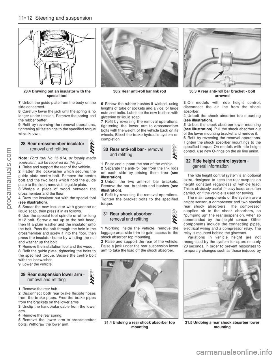
(see illustration).
5Smear the new insulator with glycerine or
liquid soap, then press it in as follows.
6Use the special tool spindle or other long
M12 bolt. Screw a nut up to the bolt head,
then fit a plain washer and the insulator onto
the bolt. Pass the bolt through the hole in the
crossmember and screw it into the floor, then
press the insulator home by winding the nut
and washer up the bolt.
7Remove the installation tool and the wood.
8Refit the guide plate, tightening the bolts to
the specified torque. Secure the centre bolt
with the lockwasher.
9Lower the vehicle.
1Remove the rear hub.
2Disconnect both rear brake flexible hoses
from the brake pipes. Free the brake pipes
from the brackets on the lower arms.
3Unclip the handbrake cable from the lower
arm.
4Remove the rear spring.
5Remove the lower arm-to-crossmember
bolts. Withdraw the lower arm.6Renew the rubber bushes if wished, using
lengths of tube or sockets and a vice, or large
nuts and bolts. Lubricate the new bushes with
glycerine or liquid soap.
7Refit by reversing the removal operations,
tightening the lower arm-to-crossmember
bolts with the weight of the vehicle back on its
wheels. Bleed the brake hydraulic system on
completion.
1Raise and support the rear of the vehicle.
2Separate the anti-roll bar from the link rods
on each side by prising them free (see
illustration).
3Unbolt the two anti-roll bar brackets.
Remove the bar, brackets and bushes (see
illustration).
4Refit by reversing the removal operations.
Tighten the bracket bolts to the specified
torque.
1Working inside the vehicle, remove the
luggage area side trim to gain access to the
shock absorber top mounting.
2Raise and support the rear of the vehicle.
Raise a jack under the rear suspension lower
arm to take the load off the shock absorber.3On models with ride height control,
disconnect the air line from the shock
absorber.
4Unbolt the shock absorber top mounting
(see illustration).
5Unbolt the shock absorber lower mounting
(see illustration). Pull the shock absorber out
of the lower mounting bracket and remove it.
6Refit by reversing the removal operations.
Tighten the shock absorber mountings to the
specified torque. On models with ride height
control, use new O-rings on the air line union.
The ride height control system is an optional
extra, designed to keep the rear suspension
height constant regardless of vehicle load.
This is obviously useful if heavy loads are often
carried, or if the vehicle is used for towing.
The main components of the system are a
height sensor, a compressor and two special
rear shock absorbers. The compressor
supplies air to the shock absorbers, so
“pumping up” the rear suspension, when so
commanded by the height sensor. Other
components include the connecting pipes,
electrical wiring and a compressor relay. The
relay is mounted behind the glovebox.
Variations in vehicle height are not
recognised by the system for approximately
20 seconds, in order to prevent responses to
temporary changes such as those induced by
32Ride height control system -
general information
31Rear shock absorber -
removal and refitting
30Rear anti-roll bar - removal
and refitting
29Rear suspension lower arm -
removal and refitting
28Rear crossmember insulator
- removal and refitting
11•12Steering and suspension
28.4 Drawing out an insulator with the
special tool
31.4 Undoing a rear shock absorber top
mounting31.5 Undoing a rear shock absorber lower
mounting
30.2 Rear anti-roll bar link rod30.3 A rear anti-roll bar bracket - bolt
arrowed
procarmanuals.com
Page 161 of 255
Where serious damage has occurred or
large areas need renewal due to neglect, it
means certainly that completely new sections
or panels will need welding in and this is best
left to professionals. If the damage is due to
impact, it will also be necessary to completely
check the alignment of the bodyshell
structure. Due to the principle of construction,
the strength and shape of the whole car can
be affected by damage to one part. In such
instances the services of a Ford agent with
specialist checking jigs are essential. If a body
is left misaligned, it is first of all dangerous as
the car will not handle properly, and secondly
uneven stresses will be imposed on the
steering, engine and transmission, causing
abnormal wear or complete failure. Tyre wear
may also be excessive.
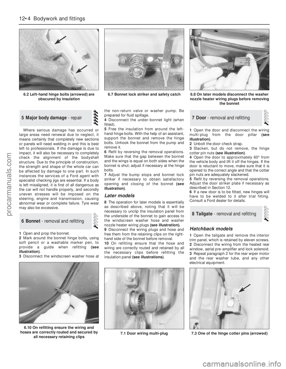
1Open and prop the bonnet.
2Mark around the bonnet hinge bolts, using
soft pencil or a washable marker pen, to
provide a guide when refitting (see
illustration).
3Disconnect the windscreen washer hose atthe non-return valve or washer pump. Be
prepared for fluid spillage.
4Disconnect the under-bonnet light (when
fitted).
5Free the insulation from around the left-
hand hinge bolts. With the help of an assistant,
support the bonnet and remove the hinge
bolts. Unhook the bonnet from the pump and
remove it.
6Refit by reversing the removal operations.
Make sure that the gap between the bonnet
and the wings is equal on both sides when the
bonnet is shut; adjust if necessary at the hinge
bolts.
7Adjust the bump stops and bonnet lock
striker if necessary to obtain satisfactory
opening and closing of the bonnet (see
illustration).
Later models
8The operation for later models is essentially
as described above, noting thatit will be
necessary to unclip the insulation panel from
the underside of the bonnet to gain access to
the windscreen washer hose and washer
nozzle heater wiring plugs (see illustration).
9Disconnect the wiring plugs and hose and
free them from the retaining clips on the right-
hand side of the bonnet before removal.
10On refitting ensure that the hose and
wiring are correctly routed and retained by all
the necessary clips before refitting the
insulation panel (see illustrations).1Open the door and disconnect the wiring
multi-plug from the door pillar (see
illustration).
2Unbolt the door check strap.
3Slacken, but do not remove, the hinge
cotter pin nuts (see illustration).
4Open the door to approximately 60°from
the vehicle body and lift it off the hinges. If the
door is reluctant to move, make sure that it is
opened to the correct angle and that the cotter
pin nuts are adequately slackened.
5Refit by reversing the removal operations.
Adjust the door striker plate if necessary as
described in Section 12.
6If a new door is to be fitted, new hinges will
have to be welded to it after trial fitting.
Consult a Ford dealer for details.
Hatchback models
1Open the tailgate and remove the interior
trim panel, which is retained by eleven screws.
2Disconnect the wiring from the heated rear
window, aerial pre-amplifier and lock solenoid.
3Repeat paragraph 2 for the rear wiper motor
and the rear washer tube, and any other
electrical equipment.
8Tailgate - removal and refitting
7Door - removal and refitting
6Bonnet - removal and refitting
5Major body damage - repair
12•4Bodywork and fittings
6.2 Left-hand hinge bolts (arrowed) are
obscured by insulation
6.10 On refitting ensure the wiring and
hoses are correctly routed and secured by
all necessary retaining clips
7.1 Door wiring multi-plug7.3 One of the hinge cotter pins (arrowed)
6.7 Bonnet lock striker and safety catch6.8 On later models disconnect the washer
nozzle heater wiring plugs before removing
the bonnet
procarmanuals.com
Page 162 of 255
4Have an assistant support the tailgate.
Disconnect the struts from the tailgate.
5Jam the tailgate latch with a piece of wood
or cardboard so that the tailgate cannot shut.
Lower the tailgate.
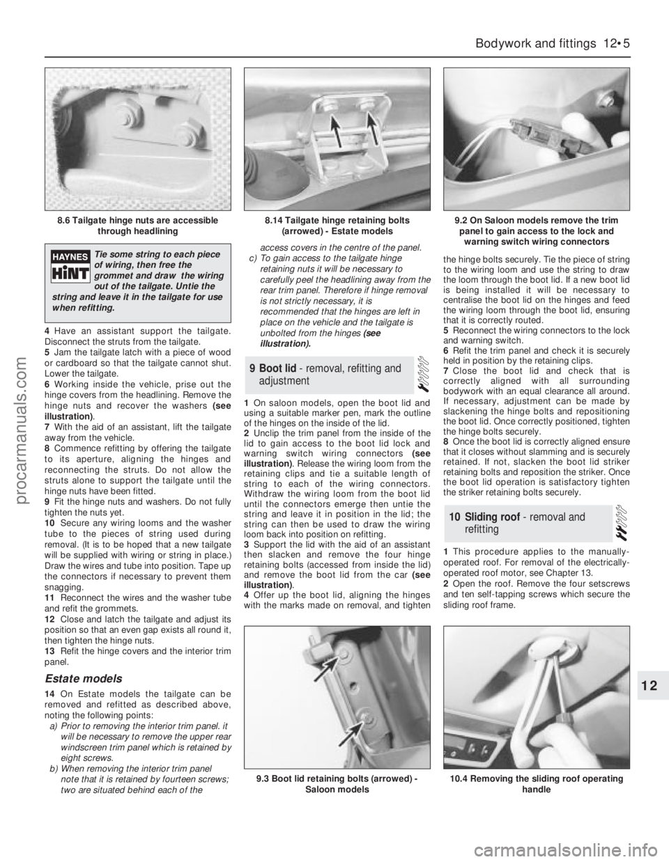
6Working inside the vehicle, prise out the
hinge covers from the headlining. Remove the
hinge nuts and recover the washers (see
illustration).
7With the aid of an assistant, lift the tailgate
away from the vehicle.
8Commence refitting by offering the tailgate
to its aperture, aligning the hinges and
reconnecting the struts. Do not allow the
struts alone to support the tailgate until the
hinge nuts have been fitted.
9Fit the hinge nuts and washers. Do not fully
tighten the nuts yet.
10Secure any wiring looms and the washer
tube to the pieces of string used during
removal. (It is to be hoped that a new tailgate
will be supplied with wiring or string in place.)
Draw the wires and tube into position. Tape up
the connectors if necessary to prevent them
snagging.
11Reconnect the wires and the washer tube
and refit the grommets.
12Close and latch the tailgate and adjust its
position so that an even gap exists all round it,
then tighten the hinge nuts.
13Refit the hinge covers and the interior trim
panel.
Estate models
14On Estate models the tailgate can be
removed and refitted as described above,
noting the following points:
a)Prior to removing the interior trim panel. it
will be necessary to remove the upper rear
windscreen trim panel which is retained by
eight screws.
b)When removing the interior trim panel
note that it is retained by fourteen screws;
two are situated behind each of theaccess covers in the centre of the panel.
c)To gain access to the tailgate hinge
retaining nuts it will be necessary to
carefully peelthe headlining away from the
rear trim panel. Therefore if hinge removal
is not strictly necessary, it is
recommended that the hinges are left in
place on the vehicle and the tailgate is
unbolted from the hinges (see
illustration).
1On saloon models, open the boot lid and
using a suitable marker pen, mark the outline
of the hinges on the inside of the lid.
2Unclip the trim panel from the inside of the
lid to gain access to the boot lid lock and
warning switch wiring connectors (see
illustration). Release the wiring loom from the
retaining clips and tie a suitable length of
string to each of the wiring connectors.
Withdraw the wiring loom from the boot lid
until the connectors emerge then untie the
string and leave it in position in the lid; the
string can then be used to draw the wiring
loom back into position on refitting.
3Support the lid with the aid of an assistant
then slacken and remove the four hinge
retaining bolts (accessed from inside the lid)
and remove the boot lid from the car (see
illustration).
4Offer up the boot lid, aligning the hinges
with the marks made on removal, and tightenthe hinge bolts securely. Tie the piece of string
to the wiring loom and use the string to draw
the loom through the boot lid. If a new boot lid
is being installed it will be necessary to
centralise the boot lid on the hinges and feed
the wiring loom through the boot lid, ensuring
that it is correctly routed.
5Reconnect the wiring connectors to the lock
and warning switch.
6Refit the trim panel and check it is securely
held in position by the retaining clips.
7Close the boot lid and check that is
correctly aligned with all surrounding
bodywork with an equal clearance all around.
If necessary, adjustment can be made by
slackening the hinge bolts and repositioning
the boot lid. Once correctly positioned, tighten
the hinge bolts securely.
8Once the boot lid is correctly aligned ensure
that it closes without slamming and is securely
retained. If not, slacken the boot lid striker
retaining bolts and reposition the striker. Once
the boot lid operation is satisfactory tighten
the striker retaining bolts securely.
1This procedure applies to the manually-
operated roof. For removal of the electrically-
operated roof motor, see Chapter 13.
2Open the roof. Remove the four setscrews
and ten self-tapping screws which secure the
sliding roof frame.
10Sliding roof - removal and
refitting
9Boot lid - removal, refitting and
adjustment
Bodywork and fittings 12•5
12
8.6 Tailgate hinge nuts are accessible
through headlining8.14 Tailgate hinge retaining bolts
(arrowed) - Estate models9.2 On Saloon models remove the trim
panel to gain access to the lock and
warning switch wiring connectors
9.3 Boot lid retaining bolts (arrowed) -
Saloon models10.4 Removing the sliding roof operating
handle
Tie some string to each piece
of wiring, then free the
grommet and draw the wiring
out of the tailgate. Untie the
string and leave it in the tailgate for use
when refitting.
procarmanuals.com
Page 166 of 255
5Free the glass from the channels. Carefully
remove the glass upwards through the
window aperture.
6Refit by reversing the removal operations.
Note that the channels are adjustable: wind
the window up and down after securing the
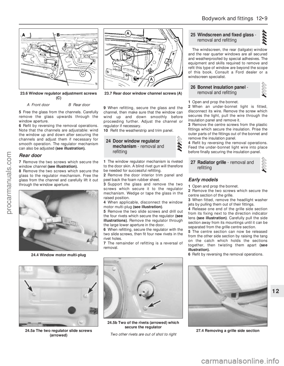
channels and adjust them if necessary for
smooth operation. The regulator mechanism
can also be adjusted (see illustration).
Rear door
7Remove the two screws which secure the
window channel (see illustration).
8Remove the two screws which secure the
glass to the regulator mechanism. Free the
glass from the channel and carefully lift it out
through the window aperture.9When refitting, secure the glass and the
channel, then make sure that the window can
wind up and down smoothly before
proceeding further. Adjust the channel or
regulator if necessary.
10Refit the weatherstrip and trim panel.
1The window regulator mechanism is riveted
to the door skin. A blind rivet gun will therefore
be needed for successful refitting.
2Remove the door interior trim panel and
peel back the foam rubber sheet.
3Support the glass and remove the two
screws which secure it to the regulator
mechanism. Wedge or tape the glass in the
raised position.
4When applicable, disconnect the window
motor multi-plug (see illustration).
5Remove the two slide screws and drill out
the four rivets which secure the regulator (see
illustrations). Remove the regulator through
the large lower aperture in the door.
6When refitting, secure the regulator with the
two slide screws, then fit four new rivets in the
rivet holes.
7The remainder of refitting is a reversal of
removal.The windscreen, the rear (tailgate) window
and the rear quarter windows are all secured
and weatherproofed by special adhesives. The
equipment and skills required to remove and
refit this type of window are beyond the scope
of this book. Consult a Ford dealer or a
windscreen specialist.
1Open and prop the bonnet.
2When an under-bonnet light is fitted,
disconnect its wire. Remove the screw which
secures the light, pull the wire through the
insulation panel and remove it.
3Remove the centre screws from the plastic
fittings which secure the insulation. Prise the
outer parts of the fittings out of the bonnet and
remove the insulation panel.
4Refit by reversing the removal operations.
Feed the under-bonnet light wire into place
before finally securing the insulation panel.
Early models
1Open and prop the bonnet.
2Remove the two screws which secure the
centre section of the grille.
3When fitted, remove the headlight washer
jets by pulling them out of their fittings.
4Release one end of the grille side section
from its fixing next to the direction indicator
lens (see illustration). Carefully pull the side
section away from its mountings until it can be
separated from the grille centre section.
5The centre section can now be released
from the other side section by raising the tang
on the catch which holds the sections
together, then twisting them apart (see
illustration).
6Refit by reversing the removal operations.
27Radiator grille - removal and
refitting
26Bonnet insulation panel -
removal and refitting
25Windscreen and fixed glass -
removal and refitting
24Door window regulator
mechanism - removal and
refitting
Bodywork and fittings 12•9
12
23.6 Window regulator adjustment screws
(C)
A Front doorB Rear door
23.7 Rear door window channel screws (A)
24.5a The two regulator slide screws
(arrowed)
24.4 Window motor multi-plug
24.5b Two of the rivets (arrowed) which
secure the regulator
Two other rivets are out of shot to right
27.4 Removing a grille side section
procarmanuals.com
Page 170 of 255
6Disconnect the glovebox arms and hinges.
Withdraw the hinge pins and remove the lid.
7Slide the auxiliary fuse panel off its
mounting and remove the glovebox light
(when fitted).
8Remove the ABS and ESC/EEC modules
(Chapter 13). Remove the two nuts and
washers from inside the glovebox.
9Remove the radio, stowage box or graphic
equaliser, ashtray, cigarette lighter panel and
(when applicable) the gear lever gaiter.
10Remove the centre console, disconnecting
switches, rear heater controls etc as
necessary.
11Remove the six screws which secure the
passenger’s side lower panel. Remove the
panel. 12Refit by reversing the removal operations,
transferring the brackets, captive nuts or other
fittings to any new panels being fitted.
Models from April 1992
13Disconnect the battery negative terminal.
14Remove the centre console.
15Remove the radio, amplifier unit and
(where necessary) the CD player.
16Remove the instrument cluster.
17Remove the steering wheel and then the
steering column direction indicator/headlight
flasher switch and windscreen wipe/wash
switch.
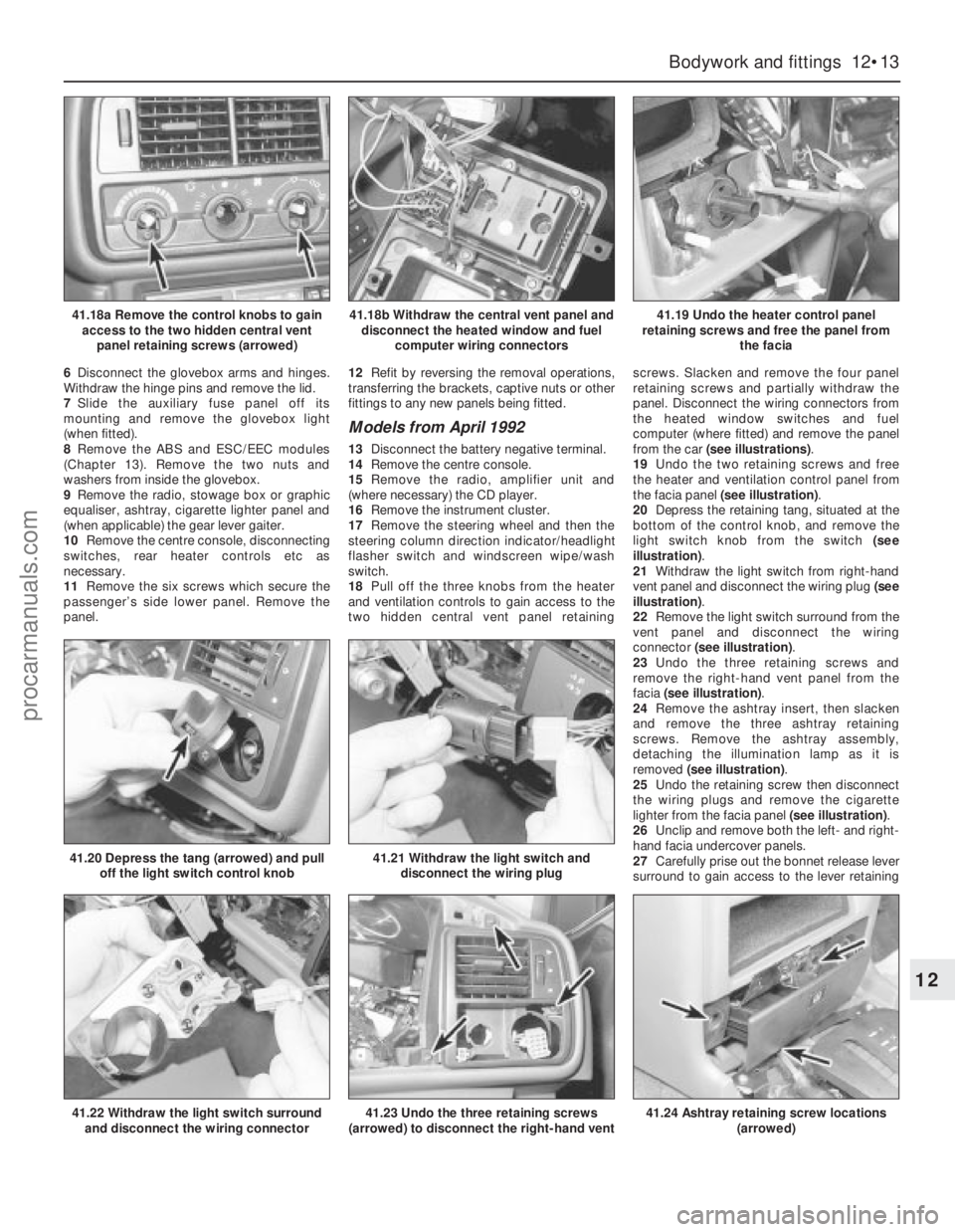
18Pull off the three knobs from the heater
and ventilation controls to gain access to the
two hidden central vent panel retainingscrews. Slacken and remove the four panel
retaining screws and partially withdraw the
panel. Disconnect the wiring connectors from
the heated window switches and fuel
computer (where fitted) and remove the panel
from the car (see illustrations).
19Undo the two retaining screws and free
the heater and ventilation control panel from
the facia panel (see illustration).
20Depress the retaining tang, situated at the
bottom of the control knob, and remove the
light switch knob from the switch (see
illustration).
21Withdraw the light switch from right-hand
vent panel and disconnect the wiring plug (see
illustration).
22Remove the light switch surround from the
vent panel and disconnect the wiring
connector (see illustration).
23Undo the three retaining screws and
remove the right-hand vent panel from the
facia (see illustration).
24Remove the ashtray insert, then slacken
and remove the three ashtray retaining
screws. Remove the ashtray assembly,
detaching the illumination lamp as it is
removed (see illustration).
25Undo the retaining screw then disconnect
the wiring plugs and remove the cigarette
lighter from the facia panel (see illustration).
26Unclip and remove both the left- and right-
hand facia undercover panels.
27Carefully prise out the bonnet release lever
surround to gain access to the lever retaining
Bodywork and fittings 12•13
12
41.18a Remove the control knobs to gain
access to the two hidden central vent
panel retaining screws (arrowed)41.18b Withdraw the central vent panel and
disconnect the heated window and fuel
computer wiring connectors41.19 Undo the heater control panel
retaining screws and free the panel from
the facia
41.22 Withdraw the light switch surround
and disconnect the wiring connector
41.20 Depress the tang (arrowed) and pull
off the light switch control knob41.21 Withdraw the light switch and
disconnect the wiring plug
41.23 Undo the three retaining screws
(arrowed) to disconnect the right-hand vent41.24 Ashtray retaining screw locations
(arrowed)
procarmanuals.com