1985 FORD GRANADA oil level
[x] Cancel search: oil levelPage 58 of 255
d)Disconnect the breather hose from the
camshaft cover.
e)Remove the distributor cap and HT leads,
and the rotor arm and housing. If
necessary, mark the HT leads to aid
refitting.
2Proceed as described in paragraphs 2 to 15
inclusive of Section 18.
3Examine the surfaces of the camshaft
journals and lobes and the contact surfaces of
the cam followers for wear. If wear is
excessive, considerable noise would have
been noticed from the top of the engine when
running, and new camshafts and followers
must be fitted. It is unlikely that this level of
wear will occur unless a considerable mileage
has been covered. Note that the cam followers
cannot be dismantled for renewal of individual
components.
4Check the camshaft bearing surfaces in the
cylinder head and the bearing caps for wear. If
excessive wear is evident, the only course of
action available is to renew the cylinder head
complete with bearing caps.
5Check the cam follower bores in the
cylinder head for wear. If excessive wear is
evident, the cylinder head must be renewed.
6Check the cam follower oil grooves and the
oil ports in the cylinder head for obstructions.
7Refit the cam followers and the camshafts as
described in paragraphs 27 to 55 of Section 18.
8If the engine is in the vehicle, reverse the
operations given in paragraph 1.
Refer to Part A, Section 15 of this Chapter,
noting the following points.
a)If the engine is in the car, refer to Chapter
6 when removing and refitting the clutch,
where applicable.
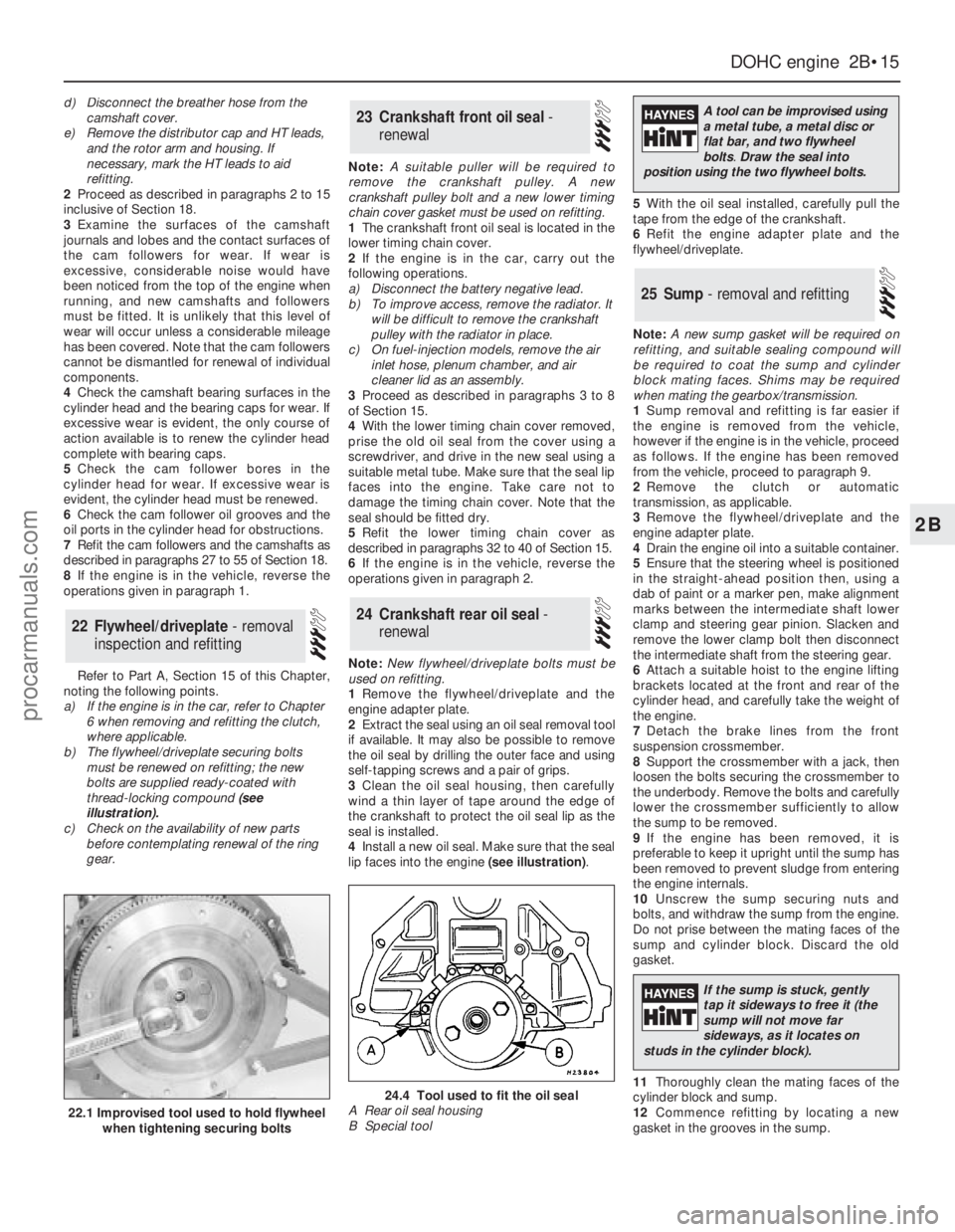
b)The flywheel/driveplate securing bolts
must be renewed on refitting; the new
bolts are supplied ready-coated with
thread-locking compound (see
illustration).
c)Check on the availability of new parts
before contemplating renewal of the ring
gear.Note: A suitable puller will be required to
remove the crankshaft pulley. A new
crankshaft pulley bolt and a new lower timing
chain cover gasket must be used on refitting.
1The crankshaft front oil seal is located in the
lower timing chain cover.
2If the engine is in the car, carry out the
following operations.
a)Disconnect the battery negative lead.
b)To improve access, remove the radiator. It
will be difficult to remove the crankshaft
pulley with the radiator in place.
c)On fuel-injection models, remove the air
inlet hose, plenum chamber, and air
cleaner lid as an assembly.
3Proceed as described in paragraphs 3 to 8
of Section 15.
4With the lower timing chain cover removed,
prise the old oil seal from the cover using a
screwdriver, and drive in the new seal using a
suitable metal tube. Make sure that the seal lip
faces into the engine. Take care not to
damage the timing chain cover. Note that the
seal should be fitted dry.
5Refit the lower timing chain cover as
described in paragraphs 32 to 40 of Section 15.
6If the engine is in the vehicle, reverse the
operations given in paragraph 2.
Note: New flywheel/driveplate bolts must be
used on refitting.
1Remove the flywheel/driveplate and the
engine adapter plate.
2Extract the seal using an oil seal removal tool
if available. It may also be possible to remove
the oil seal by drilling the outer face and using
self-tapping screws and a pair of grips.
3Clean the oil seal housing, then carefully
wind a thin layer of tape around the edge of
the crankshaft to protect the oil seal lip as the
seal is installed.
4Install a new oil seal. Make sure that the seal
lip faces into the engine (see illustration).5With the oil seal installed, carefully pull the
tape from the edge of the crankshaft.
6Refit the engine adapter plate and the
flywheel/driveplate.
Note: A new sump gasket will be required on
refitting, and suitable sealing compound will
be required to coat the sump and cylinder
block mating faces. Shims may be required
when mating the gearbox/transmission.
1Sump removal and refitting is far easier if
the engine is removed from the vehicle,
however if the engine is in the vehicle, proceed
as follows. If the engine has been removed
from the vehicle, proceed to paragraph 9.
2Remove the clutch or automatic
transmission, as applicable.
3Remove the flywheel/driveplate and the
engine adapter plate.
4Drain the engine oil into a suitable container.
5Ensure that the steering wheel is positioned
in the straight-ahead position then, using a
dab of paint or a marker pen, make alignment
marks between the intermediate shaft lower
clamp and steering gear pinion. Slacken and
remove the lower clamp bolt then disconnect
the intermediate shaft from the steering gear.
6Attach a suitable hoist to the engine lifting
brackets located at the front and rear of the
cylinder head, and carefully take the weight of
the engine.
7Detach the brake lines from the front
suspension crossmember.
8Support the crossmember with a jack, then
loosen the bolts securing the crossmember to
the underbody. Remove the bolts and carefully
lower the crossmember sufficiently to allow
the sump to be removed.
9If the engine has been removed, it is
preferable to keep it upright until the sump has
been removed to prevent sludge from entering
the engine internals.
10Unscrew the sump securing nuts and
bolts, and withdraw the sump from the engine.
Do not prise between the mating faces of the
sump and cylinder block. Discard the old
gasket.
11Thoroughly clean the mating faces of the
cylinder block and sump.
12Commence refitting by locating a new
gasket in the grooves in the sump.
25Sump - removal and refitting
24Crankshaft rear oil seal -
renewal
23Crankshaft front oil seal -
renewal
22Flywheel/driveplate - removal
inspection and refitting
DOHCengine 2B•15
2B
22.1 Improvised tool used to hold flywheel
when tightening securing bolts
24.4 Tool used to fit the oil seal
A Rear oil seal housing
B Special tool
A tool can be improvised using
a metal tube, a metal disc or
flat bar, and two flywheel
bolts.Draw the seal into
position using the two flywheel bolts.
If the sump is stuck, gently
tap it sideways to free it (the
sump will not move far
sideways, as it locates on
studs in the cylinder block).
procarmanuals.com
Page 73 of 255
3Recover the oil pump driveshaft, noting
which way round it is fitted.
4Recover the oil pump-to-block gasket.
2.4 & 2.9 litre engines
5Remove the sump.
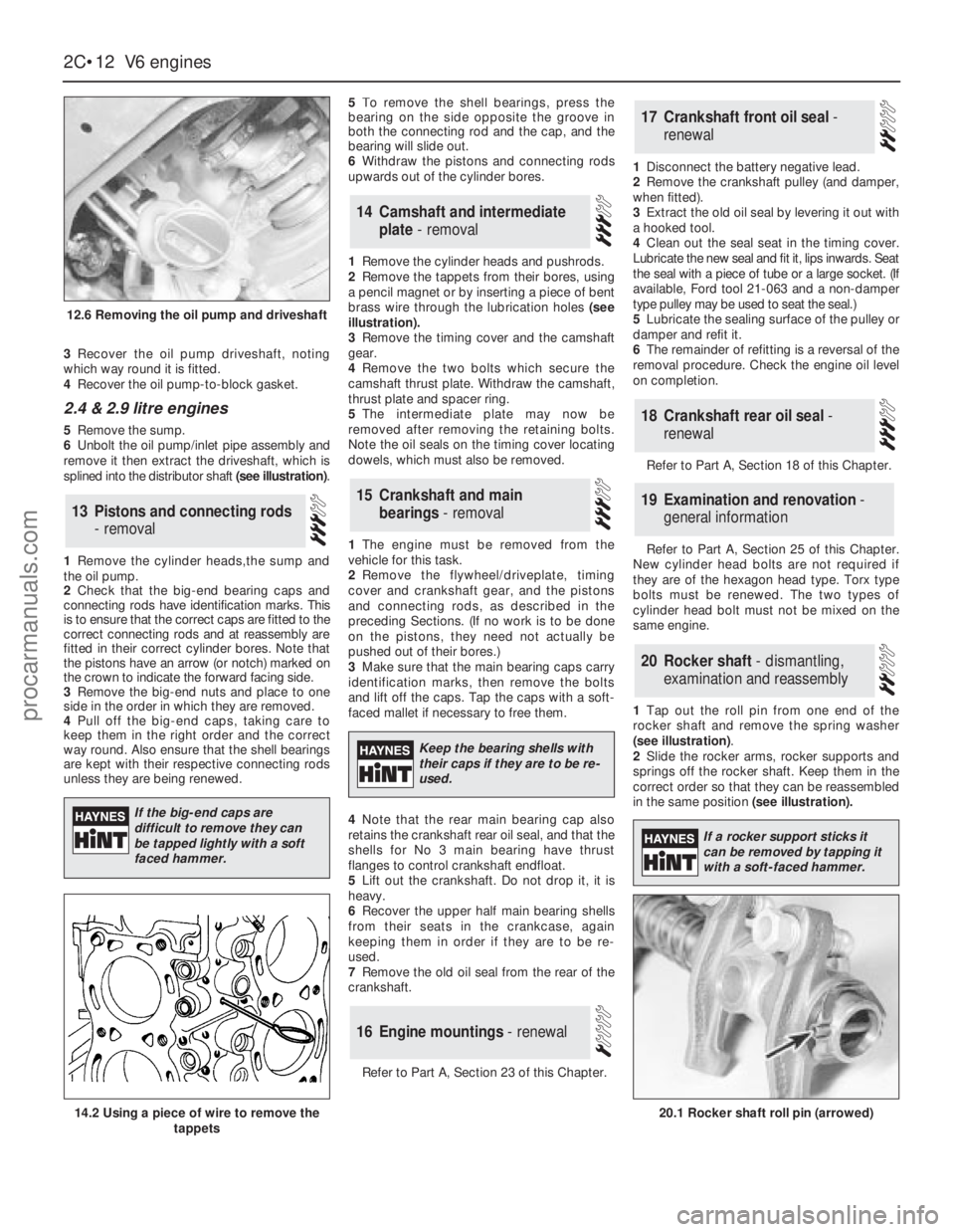
6Unbolt the oil pump/inlet pipe assembly and
remove it then extract the driveshaft, which is
splined into the distributor shaft (see illustration).
1Remove the cylinder heads,the sump and
the oil pump.
2Check that the big-end bearing caps and
connecting rods have identification marks. This
is to ensure that the correct caps are fitted to the
correct connecting rods and at reassembly are
fitted in their correct cylinder bores. Note that
the pistons have an arrow (or notch) marked on
the crown to indicate the forward facing side.
3Remove the big-end nuts and place to one
side in the order in which they are removed.
4Pull off the big-end caps, taking care to
keep them in the right order and the correct
way round. Also ensure that the shell bearings
are kept with their respective connecting rods
unless they are being renewed.5To remove the shell bearings, press the
bearing on the side opposite the groove in
both the connecting rod and the cap, and the
bearing will slide out.
6Withdraw the pistons and connecting rods
upwards out of the cylinder bores.
1Remove the cylinder heads and pushrods.
2Remove the tappets from their bores, using
a pencil magnet or by inserting a piece of bent
brass wire through the lubrication holes (see
illustration).
3Remove the timing cover and the camshaft
gear.
4Remove the two bolts which secure the
camshaft thrust plate. Withdraw the camshaft,
thrust plate and spacer ring.
5The intermediate plate may now be
removed after removing the retaining bolts.
Note the oil seals on the timing cover locating
dowels, which must also be removed.
1The engine must be removed from the
vehicle for this task.
2Remove the flywheel/driveplate, timing
cover and crankshaft gear, and the pistons
and connecting rods, as described in the
preceding Sections. (If no work is to be done
on the pistons, they need not actually be
pushed out of their bores.)
3Make sure that the main bearing caps carry
identification marks, then remove the bolts
and lift off the caps. Tap the caps with a soft-
faced mallet if necessary to free them.
4Note that the rear main bearing cap also
retains the crankshaft rear oil seal, and that the
shells for No 3 main bearing have thrust
flanges to control crankshaft endfloat.
5Lift out the crankshaft. Do not drop it, it is
heavy.
6Recover the upper half main bearing shells
from their seats in the crankcase, again
keeping them in order if they are to be re-
used.
7Remove the old oil seal from the rear of the
crankshaft.
Refer to Part A, Section 23 of this Chapter.1Disconnect the battery negative lead.
2Remove the crankshaft pulley (and damper,
when fitted).
3Extract the old oil seal by levering it out with
a hooked tool.
4Clean out the seal seat in the timing cover.
Lubricate the new seal and fit it, lips inwards. Seat
the seal with a piece of tube or a large socket. (If
available, Ford tool 21-063 and a non-damper
type pulley may be used to seat the seal.)
5Lubricate the sealing surface of the pulley or
damper and refit it.
6The remainder of refitting is a reversal of the
removal procedure. Check the engine oil level
on completion.
Refer to Part A, Section 18 of this Chapter.
Refer to Part A, Section 25 of this Chapter.
New cylinder head bolts are not required if
they are of the hexagon head type. Torx type
bolts must be renewed. The two types of
cylinder head bolt must not be mixed on the
same engine.
1Tap out the roll pin from one end of the
rocker shaft and remove the spring washer
(see illustration).
2Slide the rocker arms, rocker supports and
springs off the rocker shaft. Keep them in the
correct order so that they can be reassembled
in the same position (see illustration).
20Rocker shaft - dismantling,
examination and reassembly
19Examination and renovation -
general information
18Crankshaft rear oil seal -
renewal
17Crankshaft front oil seal -
renewal
16Engine mountings - renewal
15Crankshaft and main
bearings - removal
14Camshaft and intermediate
plate - removal
13Pistons and connecting rods
- removal
2C•12V6 engines
12.6 Removing the oil pump and driveshaft
20.1 Rocker shaft roll pin (arrowed)14.2 Using a piece of wire to remove the
tappets
If the big-end caps are
difficult to remove they can
be tapped lightly with a soft
faced hammer.
Keep the bearing shells with
their caps if they are to be re-
used.
If a rocker support sticks it
can be removed by tapping it
with a soft-faced hammer.
procarmanuals.com
Page 85 of 255
Cooling system
The cooling system is of pressurised type
and includes a front mounted crossflow
radiator, belt-driven water pump, temperature-
sensitive thermo-viscous fan (on DOHC
models, an electrically-operated cooling fan is
fitted, operated by a switch in the thermostat
housing), wax type thermostat, and an
expansion and degas tank.
The radiator matrix is of copper and brass
construction and the end tanks are of plastic.
On automatic transmission models the right-
hand side end tank incorporates the
transmission oil cooler.
The thermostat is located behind the water
outlet elbow at the front of the cylinder head
on OHCmodels, and on the front of the water
pump on V6 models. Its purpose is to ensure
rapid engine warm-up by restricting the flow of
coolant in the engine when cold, and also to
assist in regulating the normal operating
temperature of the engine.
The expansion tank incorporates a pressure
cap which effectively pressurises the cooling
system as the coolant temperature rises,
thereby increasing the boiling point of the
coolant. The tank also has a further degas
function. Any accumulation of air bubbles in
the coolant, in particular in the thermostat
housing and the radiator, is returned to the
tank and released in the air space thus
maintaining the efficiency of the coolant.
On models fitted with the auxiliary warning
system, the expansion tank contains a level
sensor which operates a warning light if the
coolant level falls significantly.
When the engine is started from cold, the
water pump circulates coolant around the
cylinder block, cylinder head(s) and inlet
manifold. The warm coolant passes through
the automatic choke housing (when
applicable) and through the heater matrix
before returning to the engine. As the coolant
expands, the level in the expansion tank rises.
Circulation of coolant through the radiator is
prevented while the thermostat is shut. When
the coolant reaches the predeterminedtemperature the thermostat opens and hot
water passes through the top hose to the top
of the radiator. As the water circulates down
through the radiator, it is cooled by the
passage of air past the radiator when the car is
in forward motion, supplemented by the action
of the thermo-viscous fan when necessary.
Having reached the bottom of the radiator, the
water is now cool and the cycle is repeated.
Circulation of water continues through the
expansion tank, inlet manifold and heater at all
times; the heater temperature control being by
an air flap.
The thermo-viscous fan is controlled by the
temperature of air behind the radiator. When
the air temperature reaches a predetermined
level, a bi-metallic coil commences to open a
valve within the unit and silicon fluid is fed
through a system of vanes. Half of the vanes
are driven directly by the water pump and the
remaining half are connected to the fan blades.
The vanes are arranged so that drive is
transmitted to the fan blades in relation to the
drag or viscosity of the fluid, and this in turn
depends on ambient temperature and engine
speed. The fan is therefore only operated when
required, and compared with direct drive type
fan represents a considerable improvement in
fuel economy, drivebelt wear and fan noise.
Air conditioning
Air conditioning is fitted as standard on
Scorpio models and is optionally available on
some other models. In conjunction with the
heater, the system enables any reasonable air
temperature to be achieved inside the car, it
also reduces the humidity of the incoming air,
aiding demisting even when cooling is not
required.
The refrigeration side of the air conditioning
system functions in a similar way to a
domestic refrigerator. A compressor, belt-
driven from the crankshaft pulley, draws
refrigerant in its gaseous phase from an
evaporator. The compressed refrigerant
passes through a condenser where it loses
heat and enters its liquid phase. After
dehydration the refrigerant returns to the
evaporator where it absorbs heat from air
passing over the evaporator fins. The
refrigerant becomes a gas again and the cycle
is repeated.Various subsidiary controls and sensors
protect the system against excessive
temperature and pressures. Additionally,
engine idle speed is increased when the
system is in use to compensate for the
additional load imposed by the compressor.
Precautions
Antifreeze mixture
Antifreeze mixture is poisonous. Keep it out
of reach of children and pets. Wash splashes
off skin and clothing with plenty of water.
Wash splashes off vehicle paintwork to avoid
discolouration.
Antifreeze/water mixture must be renewed
every two years to preserve its anti-corrosive
properties. In climates where antifreeze
protection is unnecessary, a corrosion
inhibitor may be used instead - consult a Ford
dealer. Never run the engine for long periods
with plain water as coolant. Only use the
specified antifreeze, as inferior brands may not
contain the necessary corrosion inhibitors, or
may break down at high temperatures.
Antifreeze containing methanol is particularly
to be avoided, as the methanol evaporates.
The specified mixture is 45 to 50%
antifreeze and 50 to 55% clean soft water (by
volume). Mix the required quantity in a clean
container.
Air conditioning refrigerant
Although the refrigerant is not itself toxic, in
the presence of a naked flame (or a lighted
cigarette) it forms a highly toxic gas. Liquid
refrigerant spilled on the skin will cause
frostbite. If refrigerant enters the eyes, rinse
them with a dilute solution of boric acid and
seek medical advice immediately.
In view of the above points, and of the need
for specialised equipment for evacuating and
recharging the system, any work which
requires the disconnection of a refrigerant line
must be left to a specialist.
Do not allow refrigerant lines to be exposed
to temperatures above 110°C (230°F) - eg
during welding or paint drying operations and
do not operate the air conditioning system if it
is known to be short of refrigerant, or further
damage may result.
1General information and
precautions
3•2Cooling, heating and ventilation systems
Torque wrench settingsNmlbf ft
Radiator lower mountings . . . . . . . . . . . . . . . . . . . . . . . . . . . . . . . . . . . .8 to 126 to 9
Thermostat housing bolts:
SOHC, DOHC and 2.8 litre V6 . . . . . . . . . . . . . . . . . . . . . . . . . . . . . .17 to 2013 to 15
2.4 & 2.9 litre V6 . . . . . . . . . . . . . . . . . . . . . . . . . . . . . . . . . . . . . . . . .7 to 105 to 7
Water pump bolts:
SOHC, M8 bolts . . . . . . . . . . . . . . . . . . . . . . . . . . . . . . . . . . . . . . . . .17 to 2113 to 16
SOHC, M10 bolts . . . . . . . . . . . . . . . . . . . . . . . . . . . . . . . . . . . . . . . .35 to 4226 to 31
DOHC . . . . . . . . . . . . . . . . . . . . . . . . . . . . . . . . . . . . . . . . . . . . . . . . .21 to 2816 to 21
2.8 litre V6 . . . . . . . . . . . . . . . . . . . . . . . . . . . . . . . . . . . . . . . . . . . . . .9 to 137 to 10
2.4 & 2.9 litre V6 . . . . . . . . . . . . . . . . . . . . . . . . . . . . . . . . . . . . . . . . .7 to 105 to 7
Water pump pulley bolts . . . . . . . . . . . . . . . . . . . . . . . . . . . . . . . . . . . . .21 to 2616 to 19
Water pump/alternator drivebelt tensioner bolt (DOHC) . . . . . . . . . . . .70 to 9752 to 72
Fan-to-viscous clutch bolts:
SOHC . . . . . . . . . . . . . . . . . . . . . . . . . . . . . . . . . . . . . . . . . . . . . . . . .8 to 106 to 7
V6 . . . . . . . . . . . . . . . . . . . . . . . . . . . . . . . . . . . . . . . . . . . . . . . . . . . .17 to 2313 to 17
Fan shroud bolts . . . . . . . . . . . . . . . . . . . . . . . . . . . . . . . . . . . . . . . . . . .8 to 116 to 8
Cylinder block drain plug . . . . . . . . . . . . . . . . . . . . . . . . . . . . . . . . . . . .21 to 2516 to 18
procarmanuals.com
Page 97 of 255
The exhaust system fitted in production is
made of aluminised steel, with stainless steel
used in the endplates and baffles of the rear
silencer. Individual sections of the system are
easily renewed in service.
Emission control for the UK market is
achieved largely by the inherent efficiency of
the fuel, ignition and engine management
systems. A welcome spin-off from such
efficiency is remarkably good fuel economy for
a vehicle of such size and weight.
Precautions
Fuel
Many of the procedures in this Chapter
require the removal of fuel lines and
connections which may result in some fuel
spillage. Residual pressure in fuel-injection
systems will remain in the fuel lines long after
the vehicle was last used, therefore extra care
must be taken when disconnecting a fuel line
hose. Loosen any fuel hose slowly to avoid a
sudden release of pressure which may cause
fuel spray. As an added precaution place a rag
over each union as it is disconnected to catch
any fuel which is forcibly expelled. Before
carrying out any operation on the fuel system
refer to the precautions given in “Safety first!”
at the beginning of this Manual and follow
them implicitly. Petrol is a highly dangerous
and volatile liquid and the precautions
necessary when handling it cannot be
overstressed
Tamperproof adjustment screws
Certain adjustment points in the fuel system
(and elsewhere) are protected by tamperproof
caps, plugs or seals. The purpose of such
tamperproofing is to discourage, and to deter,
adjustment by unqualified operators.
In some EU countries (though not yet in the
UK) it is an offence to drive a vehicle with
missing or broken tamperproof seals. Before
disturbing a tamperproof seal, satisfy yourself
that you will not be breaking local or national
anti-pollution regulations by doing so. Fit a
new seal when adjustment is complete when
this is required by law.
Do not break tamperproof seals on a vehicle
which is still under warranty.
Catalytic converter
The catalytic converter is a reliable and
simple device which needs no maintenance in
itself, but there are some facts of which an
owner should be aware if the converter is to
function properly for the full service life.
a)DO NOT use leaded petrol in a car
equipped with a catalytic converter the
lead will coat the precious metals,
reducing their converting efficiency and
will eventually destroy the converter.
b)Always keep the ignition and fuel systems
well-maintained in accordance with the
manufacturer’s schedule - particularly,
ensure that the air cleaner filter element,
the fuel filter and the spark plugs are
renewed at the correct interval - if the inletair/fuel mixture is allowed to become too
rich due to neglect, the unburned surplus
will enter and burn in the catalytic
converter, overheating the element and
eventually destroying the converter.
c)If the engine develops a misfire, do not
drive the car at all (or at least as little as
possible) until the fault is cured - the
misfire will allow unburned fuel to enter
the converter, which will result in
overheating, as noted above.
d)DO NOT push- or tow-start the car - this
will soak the catalytic converter in
unburned fuel, causing it to overheat when
the engine does start - see b) above.
e)DO NOT switch off the ignition at high
engine speeds - if the ignition is switched
off at anything above idle speed,
unburnedfuel will enter the (very hot)
catalytic converter, with the possible risk
of igniting on the element and damaging
the converter.
f)DO NOT use fuel or engine oil additives -
these may contain substances harmful to
the catalytic converter.
g)DO NOT continue to use the car if the
engine burns oil to the extent of leaving a
visible trail of blue smoke - the unburned
carbon deposits will clog the converter
passages and reduce the efficiency; in
severe cases the element will overheat.
h)Remember that the catalytic converter
operates at very high temperatures -
hence the heat shields on the car’s
underbody and the casing will become hot
enough to ignite combustible materials
which brush against it - DO NOT,
therefore, park the car in dry undergrowth,
over long grass or piles of dead leaves.
i)Remember that the catalytic converter is
FRAGILE, do not strike it with tools during
servicing work, take great care when
working on the exhaust system, ensure
that the converter is well clear of any jacks
or other lifting gear used to raise the car
and do not drive the car over rough
ground, road humps, etc, in such a way as
to “ground” the exhaust system.
j)In some cases, particularly when the car is
new and/or is used for stop/start driving, a
sulphurous smell (like that of rotten eggs)may be noticed from the exhaust. This is
common to many catalytic converter-
equipped cars and seems to be due to the
small amount of sulphur found in some
petrols reacting with hydrogen in the
exhaust to produce hydrogen sulphide
(H
2S) gas; while this gas is toxic, it is not
produced in sufficient amounts to be a
problem. Once the car has covered a few
thousand miles the problem should
disappear - in the meanwhile a change of
driving style or of the brand of petrol used
may effect a solution.
k)The catalytic converter, used on a well-
maintained and well-driven car, should
last for between 50 000 and 100 000 miles
- from this point on, careful checks should
be made at all specified service intervals
of the CO level to ensure that the
converter is still operating efficiently - if
the converter is no longer effective it must
be renewed.
See Chapter 1, Section 38.
1On carburettor models only, the air cleaner
can take in both hot and cold air. Hot air is
obtained from a shroud bolted to the exhaust
manifold.
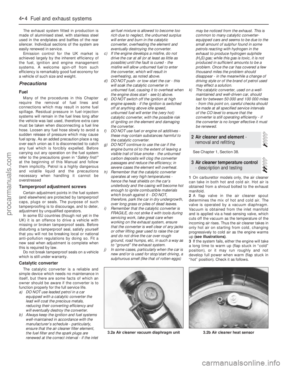
2A flap valve in the air cleaner spout
determines the mix of hot and cold air. The
valve is operated by a vacuum diaphragm.
Vacuum is obtained from the inlet manifold
and is applied via a heat-sensing valve, which
cuts off the vacuum as the temperature of the
incoming air rises. Thus the air cleaner takes in
only hot air on starting from cold, changing
progressively to cold air as the engine warms
up (see illustrations).
3If the system fails, either the engine will take
a long time to warm up (flap stuck in “cold”
position), or it may run roughly and not
develop full power when warm (flap stuck in
“hot” position). Check it as follows.
3Air cleaner temperature control
- description and testing
2Air cleaner and element -
removal and refitting
4•4Fuel and exhaust systems
3.2b Air cleaner heat sensor3.2a Air cleaner vacuum diaphragm unit
procarmanuals.com
Page 98 of 255
4With the engine cold, disconnect the cold
air inlet trunking from the spout. Look into the
spout and check that the flap valve is covering
the hot air inlet.
5Start the engine and allow it to idle. Check
that the flap moves to cover the cold air inlet. If
the flap does not move, check the diaphragm
and heat sensor as follows.
6Stop the engine. Disconnect the diaphragm
vacuum pipe from the heat sensor. Apply
vacuum to the diaphragm, using a vacuum
head pump or by connecting the pipe directly
to manifold vacuum. If the flap now moves, the
heat sensor or vacuum line was faulty. If the
flap still does not move, the diaphragm is
faulty or the flap is jammed.
7On completion reconnect the vacuum pipe
and the cold air trunking.
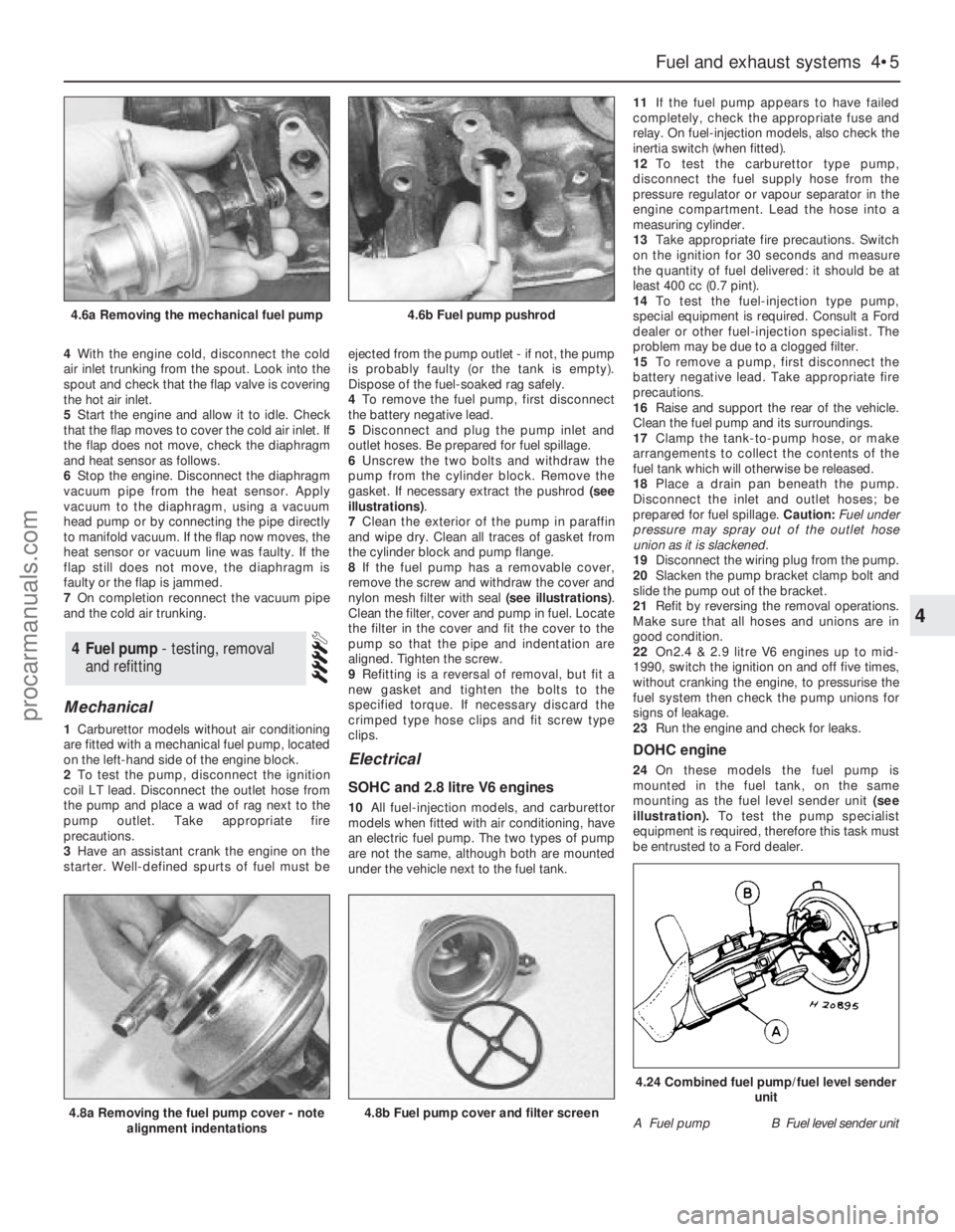
Mechanical
1Carburettor models without air conditioning
are fitted with a mechanical fuel pump, located
on the left-hand side of the engine block.
2To test the pump, disconnect the ignition
coil LT lead. Disconnect the outlet hose from
the pump and place a wad of rag next to the
pump outlet. Take appropriate fire
precautions.
3Have an assistant crank the engine on the
starter. Well-defined spurts of fuel must beejected from the pump outlet - if not, the pump
is probably faulty (or the tank is empty).
Dispose of the fuel-soaked rag safely.
4To remove the fuel pump, first disconnect
the battery negative lead.
5Disconnect and plug the pump inlet and
outlet hoses. Be prepared for fuel spillage.
6Unscrew the two bolts and withdraw the
pump from the cylinder block. Remove the
gasket. If necessary extract the pushrod (see
illustrations).
7Clean the exterior of the pump in paraffin
and wipe dry. Clean all traces of gasket from
the cylinder block and pump flange.
8If the fuel pump has a removable cover,
remove the screw and withdraw the cover and
nylon mesh filter with seal (see illustrations).
Clean the filter, cover and pump in fuel. Locate
the filter in the cover and fit the cover to the
pump so that the pipe and indentation are
aligned. Tighten the screw.
9Refitting is a reversal of removal, but fit a
new gasket and tighten the bolts to the
specified torque. If necessary discard the
crimped type hose clips and fit screw type
clips.
Electrical
SOHC and 2.8 litre V6 engines
10All fuel-injection models, and carburettor
models when fitted with air conditioning, have
an electric fuel pump. The two types of pump
are not the same, although both are mounted
under the vehicle next to the fuel tank.11If the fuel pump appears to have failed
completely, check the appropriate fuse and
relay. On fuel-injection models, also check the
inertia switch (when fitted).
12To test the carburettor type pump,
disconnect the fuel supply hose from the
pressure regulator or vapour separator in the
engine compartment. Lead the hose into a
measuring cylinder.
13Take appropriate fire precautions. Switch
on the ignition for 30 seconds and measure
the quantity of fuel delivered: it should be at
least 400 cc (0.7 pint).
14To test the fuel-injection type pump,
special equipment is required. Consult a Ford
dealer or other fuel-injection specialist. The
problem may be due to a clogged filter.
15To remove a pump, first disconnect the
battery negative lead. Take appropriate fire
precautions.
16Raise and support the rear of the vehicle.
Clean the fuel pump and its surroundings.
17Clamp the tank-to-pump hose, or make
arrangements to collect the contents of the
fuel tank which will otherwise be released.
18Place a drain pan beneath the pump.
Disconnect the inlet and outlet hoses; be
prepared for fuel spillage. Caution: Fuel under
pressure may spray out of the outlet hose
union as it is slackened.
19Disconnect the wiring plug from the pump.
20Slacken the pump bracket clamp bolt and
slide the pump out of the bracket.
21Refit by reversing the removal operations.
Make sure that all hoses and unions are in
good condition.
22On2.4 & 2.9 litre V6 engines up to mid-
1990, switch the ignition on and off five times,
without cranking the engine, to pressurise the
fuel system then check the pump unions for
signs of leakage.
23Run the engine and check for leaks.
DOHC engine
24On these models the fuel pump is
mounted in the fuel tank, on the same
mounting as the fuel level sender unit(see
illustration).To test the pump specialist
equipment is required, therefore this task must
be entrusted to a Ford dealer.
4Fuel pump - testing, removal
and refitting
Fuel and exhaust systems 4•5
4
4.6a Removing the mechanical fuel pump4.6b Fuel pump pushrod
4.8a Removing the fuel pump cover - note
alignment indentations4.8b Fuel pump cover and filter screenA Fuel pumpB Fuel level sender unit
4.24 Combined fuel pump/fuel level sender
unit
procarmanuals.com
Page 109 of 255
9Unscrew the securing nut, and release the
air inlet tube from the bracket on the engine
compartment front panel.
10Disconnect the wiring plug from the idle
speed control valve.
11Release the air cleaner lid securing clips,
then remove the air inlet tube, plenum
chamber, and air cleaner lid as an assembly,
disconnecting the breather hose from the air
inlet tube.
12Unscrew the two securing bolts, and
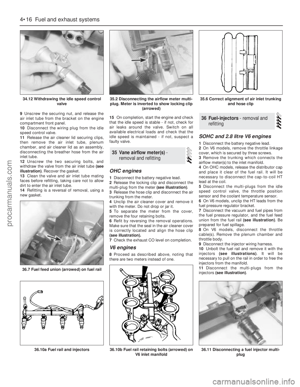
withdraw the valve from the air inlet tube (see
illustration). Recover the gasket.
13Clean the valve and air inlet tube mating
faces before refitting, taking care not to allow
dirt to enter the air inlet tube.
14Refitting is a reversal of removal, using a
new gasket.15On completion, start the engine and check
that the idle speed is stable - if not, check for
air leaks around the valve. Switch on all
available electrical loads and check that the
idle speed is maintained - if not, suspect a
faulty valve.
OHC engines
1Disconnect the battery negative lead.
2Release the locking clip and disconnect the
multi-plug from the meter (see illustration).
3Release the hose clip and disconnect the air
trunking from the meter.
4Unclip the air cleaner cover and remove it
with the meter. Do not drop or jar it.
5To separate the meter from the cover,
remove the four retaining bolts.
6Refit by reversing the removal operations.
Make sure that the seal in the air cleaner cover
is correctly located and align the hose clip
(seeillustration).
7Check the exhaust CO level on completion.
V6 engines
8Proceed as described above, noting that
there are two meters instead of one.
SOHC and 2.8 litre V6 engines
1Disconnect the battery negative lead.
2On V6 models, remove the throttle linkage
cover, which is secured by three screws.
3Remove the trunking which connects the
airflow meter(s) to the inlet manifold.
4On OHCmodels, release the distributor cap
and place it clear of the fuel rail. It will be
necessary to disconnect the cap-to-coil HT
lead at the coil.
5Disconnect the multi-plugs from the idle
speed control valve, the throttle position
sensor and the coolant temperature sensor.
6On V6 models, unclip the HT leads from the
fuel pressure regulator bracket.
7Disconnect the vacuum and fuel pipes from
the fuel pressure regulator, and the fuel feed
union from the fuel rail (see illustration). Be
prepared for fuel spillage.
8On V6 models, disconnect the throttle
cable(s). Remove the plenum chamber and
throttle body.
9Disconnect the injector wiring harness.
10Unbolt the fuel rail and remove it with the
injectors (see illustrations). It will be
necessary to pull on the rail in order to free the
injectors from the manifold.
11Disconnect the multi-plugs from the
injectors (see illustration).
36Fuel-injectors - removal and
refitting
35Vane airflow meter(s) -
removal and refitting
4•16Fuel and exhaust systems
34.12 Withdrawing the idle speed control
valve
36.7 Fuel feed union (arrowed) on fuel rail
36.10a Fuel rail and injectors36.10b Fuel rail retaining bolts (arrowed) on
V6 inlet manifold36.11 Disconnecting a fuel injector multi-
plug
35.2 Disconnecting the airflow meter multi-
plug. Meter is inverted to show locking clip
(arrowed)35.6 Correct alignment of air inlet trunking
and hose clip
procarmanuals.com
Page 110 of 255
12Extract the retaining clips and pull the
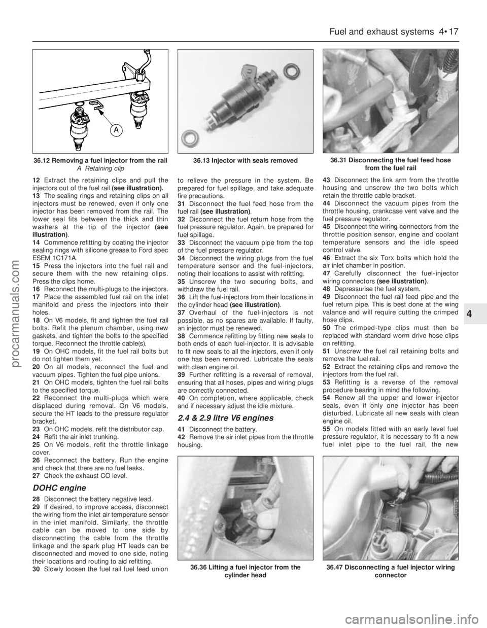
injectors out of the fuel rail(see illustration).
13The sealing rings and retaining clips on all
injectors must be renewed, even if only one
injector has been removed from the rail. The
lower seal fits between the thick and thin
washers at the tip of the injector (see
illustration).
14Commence refitting by coating the injector
sealing rings with silicone grease to Ford spec
ESEM 1C171A.
15Press the injectors into the fuel rail and
secure them with the new retaining clips.
Press the clips home.
16Reconnect the multi-plugs to the injectors.
17Place the assembled fuel rail on the inlet
manifold and press the injectors into their
holes.
18On V6 models, fit and tighten the fuel rail
bolts. Refit the plenum chamber, using new
gaskets, and tighten the bolts to the specified
torque. Reconnect the throttle cable(s).
19On OHCmodels, fit the fuel rail bolts but
do not tighten them yet.
20On all models, reconnect the fuel and
vacuum pipes. Tighten the fuel pipe unions.
21On OHCmodels, tighten the fuel rail bolts
to the specified torque.
22Reconnect the multi-plugs which were
displaced during removal. On V6 models,
secure the HT leads to the pressure regulator
bracket.
23On OHCmodels, refit the distributor cap.
24Refit the air inlet trunking.
25On V6 models, refit the throttle linkage
cover.
26Reconnect the battery. Run the engine
and check that there are no fuel leaks.
27Check the exhaust CO level.
DOHC engine
28Disconnect the battery negative lead.
29If desired, to improve access, disconnect
the wiring from the inlet air temperature sensor
in the inlet manifold. Similarly, the throttle
cable can be moved to one side by
disconnecting the cable from the throttle
linkage and the spark plug HT leads can be
disconnected and moved to one side, noting
their locations and routing to aid refitting.
30Slowly loosen the fuel rail fuel feed unionto relieve the pressure in the system. Be
prepared for fuel spillage, and take adequate
fire precautions.
31Disconnect the fuel feed hose from the
fuel rail (see illustration).
32Disconnect the fuel return hose from the
fuel pressure regulator. Again, be prepared for
fuel spillage.
33Disconnect the vacuum pipe from the top
of the fuel pressure regulator.
34Disconnect the wiring plugs from the fuel
temperature sensor and the fuel-injectors,
noting their locations to assist with refitting.
35Unscrew the two securing bolts, and
withdraw the fuel rail.
36Lift the fuel-injectors from their locations in
the cylinder head (see illustration).
37Overhaul of the fuel-injectors is not
possible, as no spares are available. If faulty,
an injector must be renewed.
38Commence refitting by fitting new seals to
both ends of each fuel-injector. It is advisable
to fit new seals to all the injectors, even if only
one has been removed. Lubricate the seals
with clean engine oil.
39Further refitting is a reversal of removal,
ensuring that all hoses, pipes and wiring plugs
are correctly connected.
40On completion, where applicable, check
and if necessary adjust the idle mixture.
2.4 & 2.9 litre V6 engines
41Disconnect the battery.
42Remove the air inlet pipes from the throttle
housing.43Disconnect the link arm from the throttle
housing and unscrew the two bolts which
retain the throttle cable bracket.
44Disconnect the vacuum pipes from the
throttle housing, crankcase vent valve and the
fuel pressure regulator.
45Disconnect the wiring connectors from the
throttle position sensor, engine and coolant
temperature sensors and the idle speed
control valve.
46Extract the six Torx bolts which hold the
air inlet chamber in position.
47Carefully disconnect the fuel-injector
wiring connectors (see illustration).
48Depressurise the fuel system.
49Disconnect the fuel rail feed pipe and the
fuel return pipe. This is best done at the wing
valance and will require cutting the crimped
hose clips.
50The crimped-type clips must then be
replaced with standard worm drive hose clips
on refitting.
51Unscrew the fuel rail retaining bolts and
remove the fuel rail.
52Extract the retaining clips and remove the
injectors from the fuel rail.
53Refitting is a reverse of the removal
procedure bearing in mind the following.
54Renew all the upper and lower injector
seals, even if only one injector has been
disturbed. Lubricate all new seals with clean
engine oil.
55On models fitted with an early level fuel
pressure regulator, it is necessary to fit a new
fuel inlet pipe to the fuel rail, the new
Fuel and exhaust systems 4•17
4
36.12 Removing a fuel injector from the rail
A Retaining clip36.13 Injector with seals removed36.31 Disconnecting the fuel feed hose
from the fuel rail
36.36 Lifting a fuel injector from the
cylinder head36.47 Disconnecting a fuel injector wiring
connector
procarmanuals.com
Page 111 of 255
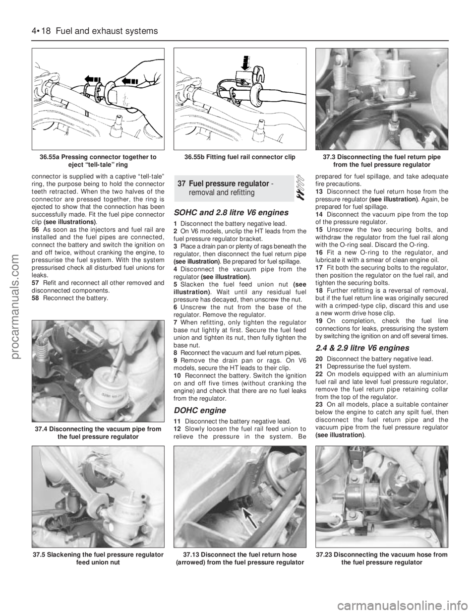
connector is supplied with a captive “tell-tale”
ring, the purpose being to hold the connector
teeth retracted. When the two halves of the
connector are pressed together, the ring is
ejected to show that the connection has been
successfully made. Fit the fuel pipe connector
clip (see illustrations).
56As soon as the injectors and fuel rail are
installed and the fuel pipes are connected,
connect the battery and switch the ignition on
and off twice, without cranking the engine, to
pressurise the fuel system. With the system
pressurised check all disturbed fuel unions for
leaks.
57Refit and reconnect all other removed and
disconnected components.
58Reconnect the battery.
SOHC and 2.8 litre V6 engines
1Disconnect the battery negative lead.
2On V6 models, unclip the HT leads from the
fuel pressure regulator bracket.
3Place a drain pan or plenty of rags beneath the
regulator, then disconnect the fuel return pipe
(see illustration). Be prepared for fuel spillage.
4Disconnect the vacuum pipe from the
regulator (see illustration).
5Slacken the fuel feed union nut (see
illustration). Wait until any residual fuel
pressure has decayed, then unscrew the nut.
6Unscrew the nut from the base of the
regulator. Remove the regulator.
7When refitting, only tighten the regulator
base nut lightly at first. Secure the fuel feed
union and tighten its nut, then fully tighten the
base nut.
8Reconnect the vacuum and fuel return pipes.
9Remove the drain pan or rags. On V6
models, secure the HT leads to their clip.
10Reconnect the battery. Switch the ignition
on and off five times (without cranking the
engine) and check that there are no fuel leaks
from the regulator.
DOHC engine
11Disconnect the battery negative lead.
12Slowly loosen the fuel rail feed union to
relieve the pressure in the system. Beprepared for fuel spillage, and take adequate
fire precautions.
13Disconnect the fuel return hose from the
pressure regulator (see illustration). Again, be
prepared for fuel spillage.
14Disconnect the vacuum pipe from the top
of the pressure regulator.
15Unscrew the two securing bolts, and
withdraw the regulator from the fuel rail along
with the O-ring seal. Discard the O-ring.
16Fit a new O-ring to the regulator, and
lubricate it with a smear of clean engine oil.
17Fit both the securing bolts to the regulator,
then position the regulator on the fuel rail, and
tighten the securing bolts.
18Further refitting is a reversal of removal,
but if the fuel return line was originally secured
with a crimped-type clip, discard this and use
a new worm drive hose clip.
19On completion, check the fuel line
connections for leaks, pressurising the system
by switching the ignition on and off several times.
2.4 & 2.9 litre V6 engines
20Disconnect the battery negative lead.
21Depressurise the fuel system.
22On models equipped with an aluminium
fuel rail and late level fuel pressure regulator,
remove the fuel return pipe retaining collar
from the top of the regulator.
23On all models, place a suitable container
below the engine to catch any spilt fuel, then
disconnect the fuel return pipe and the
vacuum pipe from the fuel pressure regulator
(see illustration).
37Fuel pressure regulator -
removal and refitting
4•18Fuel and exhaust systems
36.55a Pressing connector together to
eject “tell-tale” ring
37.4 Disconnecting the vacuum pipe from
the fuel pressure regulator
37.5 Slackening the fuel pressure regulator
feed union nut37.13 Disconnect the fuel return hose
(arrowed) from the fuel pressure regulator37.23 Disconnecting the vacuum hose from
the fuel pressure regulator
36.55b Fitting fuel rail connector clip37.3 Disconnecting the fuel return pipe
from the fuel pressure regulator
procarmanuals.com