1985 FORD GRANADA spark plugs
[x] Cancel search: spark plugsPage 3 of 255
1•2
Every 12 000 miles (20 000 km) or
12 months – whichever comes sooner
m mCheck operation of latches, check straps and locks; lubricate if
necessary (Section 19)
m mCheck condition and tension of auxiliary drivebelt(s); adjust or
renew as necessary (Section 21)
m mCheck tightness of battery terminals, clean and neutralise
corrosion if necessary (Section 22)
m mCheck engine valve clearances (Section 23) m
mCheck tightness of inlet manifold bolts (V6 only) (Section 24) m
mRenew spark plugs (Section 20) m
mClean air conditioning condenser fins (when applicable)
(Section 25)
m mCheck air conditioning refrigerant charge (when applicable)
(Section 26)
m mCheck manual gearbox oil level (Section 18) m
mCheck final drive oil level (Section 27) m
mLubricate automatic transmission selector/kickdown linkage
(Section 28)
m mCheck security and condition of steering and suspension
components, gaiters and boots (Section 29)
m mCheck condition and security of driveshaft joints (Section 30) m
mInspect underbody and panels for corrosion or other damage
(Section 31)
m mInspect brake pipes and hoses (Section 32) m
mClean idle speed control linkage at throttle (when applicable)
(Section 33)
m mRoad test and check operation of ABS (Section 34)m
mCheck automatic transmission fluid level (engine hot)
(Section 17)
m mCheck engine for satisfactory hot starting (Section 37)m
mCheck that automatic choke is fully off with engine hot (not fuel-
injection models) (Section 36)
m mCheck power steering fluid level (when applicable) (Section 35)
Every 24 000 miles (40 000 km) or
2 years - whichever comes sooner
m
mRenew air cleaner element (Section 38) m
mClean and inspect distributor cap, rotor arm, HT leads and coil
tower (Section 39)
m mAdjust automatic transmission brake bands (Section 40)m
mRenew fuel filter (fuel-injection models only) (Section 41) m
mRenew crankcase ventilation vent valve (carburettor models)
(Section 42)
Every 36 000 miles (60 000 km) or
3 years - whichever comes sooner
m
mRenew brake hydraulic system seals and hoses if necessary
(Section 43)
m mRenew brake hydraulic fluid (Section 44) m
mRenew camshaft drivebelt on SOHC models - recommended as
a precautionary measure (Section 45)
Every 2 years - regardless of mileage
m
mRenew coolant (Section 46)
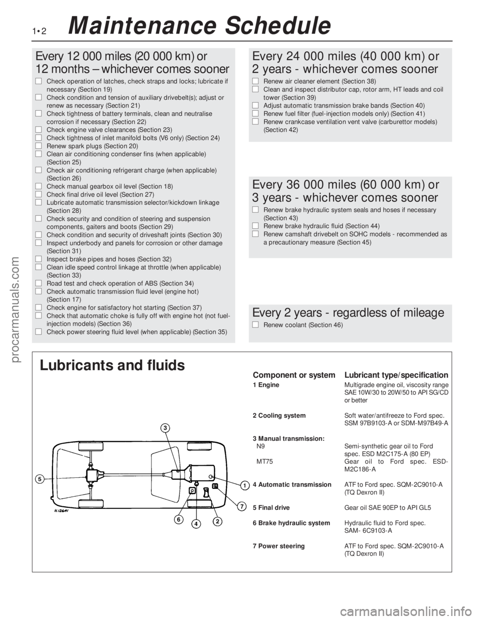
Lubricants and fluidsComponent or systemLubricant type/specification
1 EngineMultigrade engine oil, viscosity range
SAE 10W/30 to 20W/50 to API SG/CD
or better
2 Cooling systemSoft water/antifreeze to Ford spec.
SSM 97B9103-A or SDM-M97B49-A
3 Manual transmission:
N9Semi-synthetic gear oil to Ford
spec. ESD M2C175-A (80 EP)
MT75Gear oil to Ford spec. ESD-
M2C186-A
4 Automatic transmissionATF to Ford spec. SQM-2C9010-A
(TQ Dexron II)
5 Final driveGear oil SAE 90EP to APIGL5
6 Brake hydraulic systemHydraulic fluid to Ford spec.
SAM- 6C9103-A
7 Power steeringATFto Ford spec. SQM-2C9010-A
(TQDexron II)
Maintenance Schedule
procarmanuals.com
Page 7 of 255
1•6Maintenance Procedures
This Chapter is designed to help the home
mechanic maintain his/her vehicle for safety,
economy, long life and peak performance.
The Chapter contains a master maintenance
schedule, followed by Sections dealing
specifically with each task in the schedule.
Visual checks, adjustments, component
renewal and other helpful items are included.
Refer to the accompanying illustrations of the
engine compartment and the underside of the
vehicle for the locations of the various
components.
Servicing your vehicle in accordance with
the mileage/time maintenance schedule and
the following Sections will provide a planned
maintenance programme, which should result
in a long and reliable service life. This is a
comprehensive plan, so maintaining some
items but not others at the specified service
intervals, will not produce the same results.
As you service your vehicle, you will
discover that many of the procedures can -
and should - be grouped together, because of
the particular procedure being performed, or
because of the close proximity of two
otherwise-unrelated components to one
another. For example, if the vehicle is raised
for any reason, the exhaust can be inspected
at the same time as the suspension and
steering components.
The first step in this maintenanceprogramme is to prepare yourself before the
actual work begins. Read through all the
Sections relevant to the work to be carried out,
then make a list and gather together all the
parts and tools required. If a problem is
encountered, seek advice from a parts
specialist, or a dealer service department.
If, from the time the vehicle is new, the
routine maintenance schedule is followed
closely, and frequent checks are made of fluid
levels and high-wear items, as suggested
throughout this manual, the engine will be kept
in relatively good running condition, and the
need for additional work will be minimised.
It is possible that there will be times when
the engine is running poorly due to the lack of
regular maintenance. This is even more likely if
a used vehicle, which has not received regular
and frequent maintenance checks, is
purchased. In such cases, additional work
may need to be carried out, outside of the
regular maintenance intervals.
If engine wear is suspected, a compression
test will provide valuable information regarding
the overall performance of the main internal
components. Such a test can be used as a
basis to decide on the extent of the work to be
carried out. If, for example, a compression test
indicates serious internal engine wear,
conventional maintenance as described in this
Chapter will not greatly improve theperformance of the engine, and may prove a
waste of time and money, unless extensive
overhaul work is carried out first.
The following series of operations are those
most often required to improve the
performance of a generally poor-running
engine:
Primary operations
a)Clean, inspect and test the battery
(Section 6)
b)Check all the engine-related fluids
(Section 3).
c)Check the condition and tension of the
auxiliary drivebelt (Section 21).
d)Renew the spark plugs (Section 20).
e)Inspect the distributor cap, rotor arm and
HT leads - as applicable (Chapter 5).
f)Check the condition of the air cleaner filter
element, and renew if necessary (Section 38).
g)Renew the fuel filter (Section 41).
h)Check the condition of all hoses, and
check for fluid leaks (Section 10).
i)Check the idle speed and mixture settings
- as applicable (Chapter 4).
If the above operations do not prove fully
effective, carry out the following secondary
operations:
Secondary operations
a)Check the charging system (Chapter 5).
b)Check the ignition system (Chapter 5).
c)Check the fuel system (Chapter 4).
d)Renew the distributor cap and rotor arm -
as applicable (Chapter 5).
f)Renew the ignition HT leads - as
applicable (Chapter 5).
2Intensive maintenance
1Introduction
Engine oil
1Check the oil level as follows.
2With the vehicle parked on level ground,
and with the engine having been stopped for a
few minutes, open and prop the bonnet.
Withdraw the dipstick, wipe it on a clean ragand re-insert it fully. Withdraw it again and
read the oil level relative to the marks on the
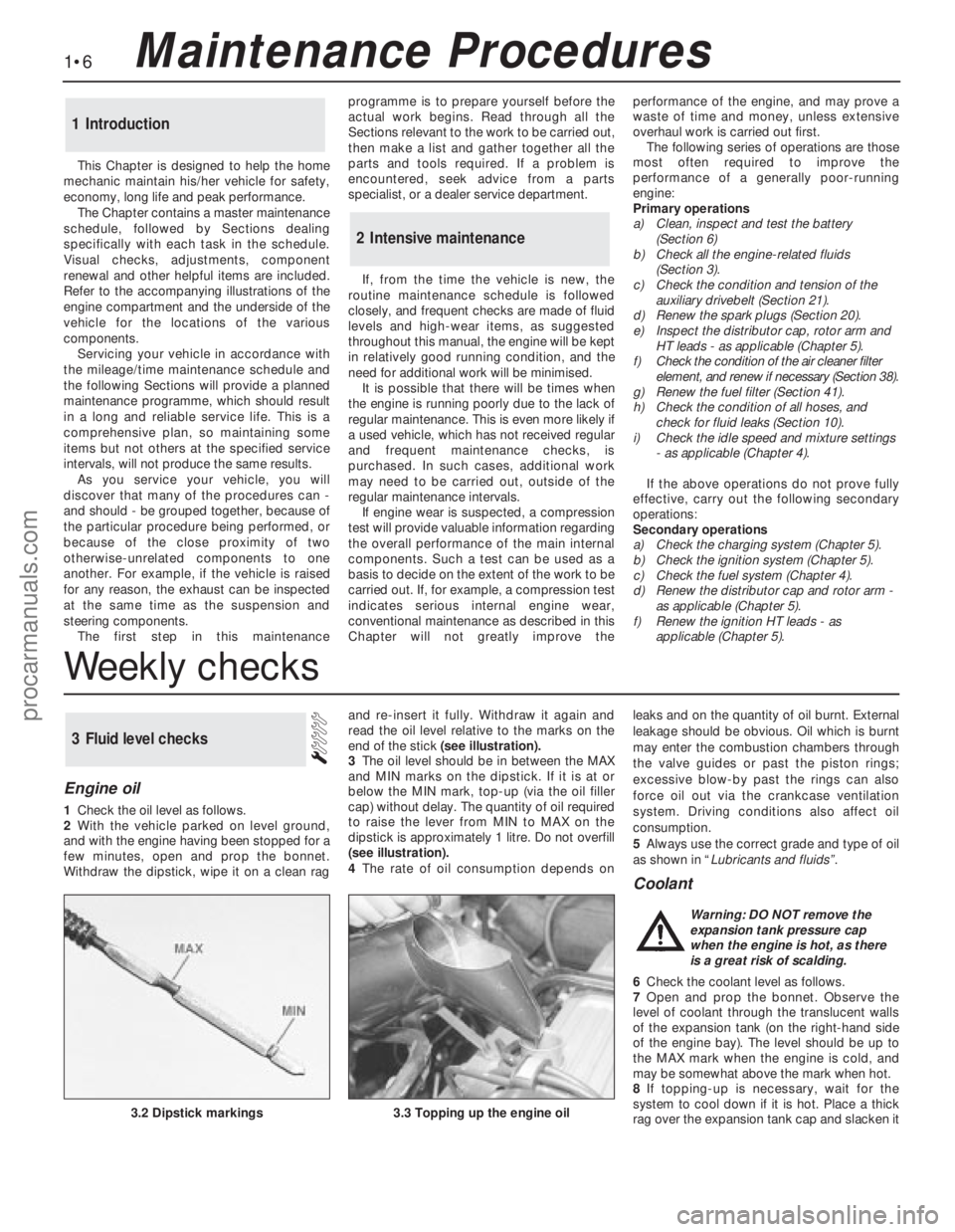
end of the stick (see illustration).
3The oil level should be in between the MAX
and MIN marks on the dipstick. If it is at or
below the MIN mark, top-up (via the oil filler
cap) without delay. The quantity of oil required
to raise the lever from MIN to MAX on the
dipstick is approximately 1 litre. Do not overfill
(see illustration).
4The rate of oil consumption depends onleaks and on the quantity of oil burnt. External
leakage should be obvious. Oil which is burnt
may enter the combustion chambers through
the valve guides or past the piston rings;
excessive blow-by past the rings can also
force oil out via the crankcase ventilation
system. Driving conditions also affect oil
consumption.
5Always use the correct grade and type of oil
as shown in “Lubricants and fluids”.
Coolant
6Check the coolant level as follows.
7Open and prop the bonnet. Observe the
level of coolant through the translucent walls
of the expansion tank (on the right-hand side
of the engine bay). The level should be up to
the MAX mark when the engine is cold, and
may be somewhat above the mark when hot.
8If topping-up is necessary, wait for the
system to cool down if it is hot. Place a thick
rag over the expansion tank cap and slacken it
3Fluid level checks
3.2 Dipstick markings3.3 Topping up the engine oil
Warning: DO NOT remove the
expansion tank pressure cap
when the engine is hot, as there
is a great risk of scalding.
Weekly checks
procarmanuals.com
Page 13 of 255
1Work around the vehicle, and lubricate the
hinges and locks with a light machine oil.
2Lightly lubricate the bonnet release
mechanism and exposed sections of inner
cable with a smear of grease.
3Check the security and operation of all
hinges, latches and locks, adjusting them
where required. Where applicable, check the
operation of the central locking system.
4Check the condition and operation of the
tailgate struts, renewing them if either is
leaking or is no longer able to support the
tailgate securely when raised.
SOHC and V6 engines
1The correct functioning of the spark plugs is
vital for the correct running and efficiency of
the engine. It is essential that the plugs fitted
are appropriate for the engine.
2Make sure that the ignition is switched off
before inspecting the HT leads to see if they
carry their cylinder numbers - if not, number
each lead using sticky tape or paint.
3Pull the HT lead connectors off the plugs.
Pull on the connectors, not on the leads.
4Blow away any dirt from around the spark
plug recesses in the cylinder head(s).
5Unscrew and remove the plugs, using a
proprietary plug spanner or a spark plug
socket, extension and ratchet.
6The condition of the plugs will tell much
about the overall condition of the engine. If the
insulator nose of the spark plug is clean and
white, with no deposits, this is indicative of a
weak mixture or too hot a plug (a hot plug
transfers heat away from the electrode slowly,
a cold plug transfers heat away quickly).
7If the tip and insulator nose are covered with
hard black-looking deposits, then this is
indicative that the mixture is too rich. Should
the plug be black and oily, then it is likely that
the engine is fairly worn, as well as the mixture
being too rich.
8If the insulator nose is covered with light tan
to greyish-brown deposits, then the mixture is
correct, and it is likely that the engine is in
good condition.
9Apply a smear of anti-seize compound to
the threads of the new plugs. Make sure that
theinsulators are clean and that the screwed
HT lead adapters are tight. Pay particular
attention to the plug seating surfaces on OHC
engines, since these plugs have no sealing
washers (“taper seat” type) and any dirt will
cause a bad seal.
10Screw each plug into its hole by hand. If a
plug is reluctant to go in, do not force it with a
spanner, but unscrew it and try again. If the
plug is cross-threaded, it is the cylinder head
which will be damaged.11Final tightening of the spark plugs should
ideally be carried out using a torque wrench.
The tightening torques are given in the
Specifications. If a torque wrench is not
available, tighten the plugs beyond the point
where they contact the head as follows:
OHC (taper seat plugs) - One-sixteenth of a
turn maximum
V6 (plugs with washers) - One-quarter of a
turn maximum
12If the taper seat type of plug is
overtightened, the sealing faces will bite
together and removal will be very difficult.
13Refit the HT leads to the plugs, paying
attention to the cylinder numbers. Push each
connector firmly onto its plug.
14Run the engine to verify that the HT leads
have been refitted correctly.
DOHC engines
15Proceed as described above whilst noting
the following points.
a)Remove the air cleaner as described in
Chapter 4.
b)The minimal length of number 3 HT lead
makes removal from the spark plug
difficult. It is advisable to remove this lead
from the distributor prior to removing it
from the spark plug.
c)The spark plugs are deeply recessed in
the cylinder head and it will be necessary
to use a spark plug socket with a long
extension bar. If possible, use a spark plug
socket with a rubber grip inside as this will
hold onto the spark plug once loosened
and will enable the spark plugs to be
withdrawn and refitted more easily.
SOHC and all V6 engines
1All of these engines have one or two
drivebelts which drive the water pump and
alternator from the crankshaft pulley. When
power steering is fitted, the same belts drive
the steering pump. The air conditioning
compressor, when fitted, is driven
independently.
2Periodically inspect the drivebelt(s) for
fraying, cracks, glazing or other damage. Turn
the engine so that the full length of the belt(s)
can be viewed. Renew belts which are in poor
condition. When twin drivebelts are fitted, both
must be renewed together, even if only one is
damaged.
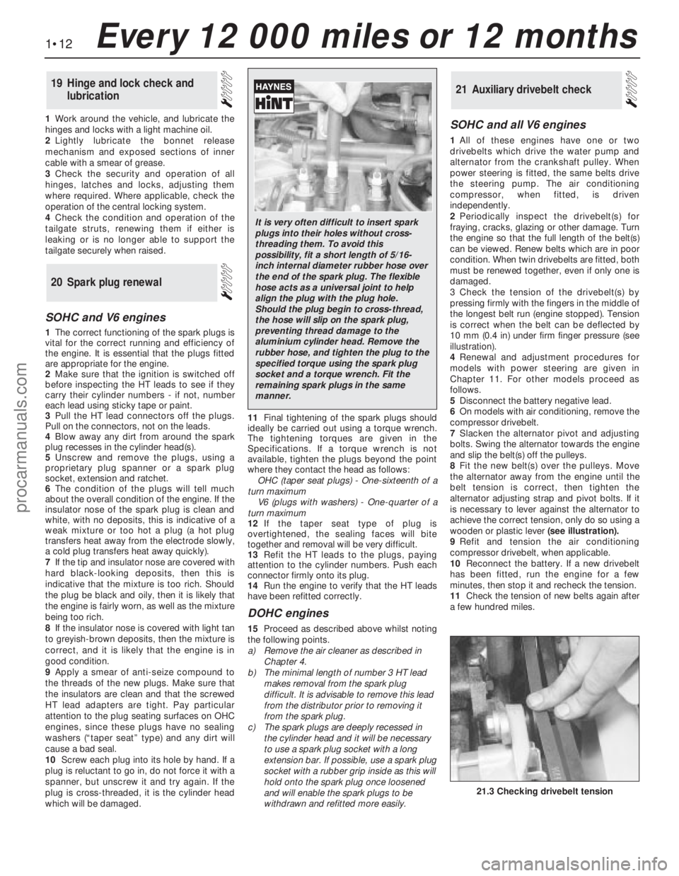
3Check the tension of the drivebelt(s) by
pressing firmly with the fingers in the middle of
the longest belt run (engine stopped). Tension
is correct when the belt can be deflected by
10 mm (0.4 in) under firm finger pressure (see
illustration).
4Renewal and adjustment procedures for
models with power steering are given in
Chapter 11. For other models proceed as
follows.
5Disconnect the battery negative lead.
6On models with air conditioning, remove the
compressor drivebelt.
7Slacken the alternator pivot and adjusting
bolts. Swing the alternator towards the engine
and slip the belt(s) off the pulleys.
8Fit the new belt(s) over the pulleys. Move
the alternator away from the engine until the
belt tension is correct, then tighten the
alternator adjusting strap and pivot bolts. If it
is necessary to lever against the alternator to
achieve the correct tension, only do so using a
wooden or plastic lever(seeillustration).
9Refit and tension the air conditioning
compressor drivebelt, when applicable.
10Reconnect the battery. If a new drivebelt
has been fitted, run the engine for a few
minutes, then stop it and recheck the tension.
11Check the tension of new belts again after
a few hundred miles.
21Auxiliary drivebelt check
20Spark plug renewal
19Hinge and lock check and
lubrication
1•12Every 12 000 miles or 12 months
21.3 Checking drivebelt tension
It is very often difficult to insert spark
plugs into their holes without cross-
threading them. To avoid this
possibility, fit a short length of 5/16-
inch internal diameter rubber hose over
the end of the spark plug. The flexible
hose acts as a universal joint to help
align the plug with the plug hole.
Should the plug begin to cross-thread,
the hose will slip on the spark plug,
preventing thread damage to the
aluminium cylinder head. Remove the
rubber hose, and tighten the plug to the
specified torque using the spark plug
socket and a torque wrench. Fit the
remaining spark plugs in the same
manner.
procarmanuals.com
Page 14 of 255
DOHC engines
12On this engine, the coolant/alternator
drivebelt also drives the power steering pump
and (where applicable) the air conditioning
compressor. The drivebelt tension is set by an
automatic tensioner assembly.
13The condition of the drivebelt should be
checked as described above.
14An idea of the amount of wear which has
taken place on the belt can be gained from the
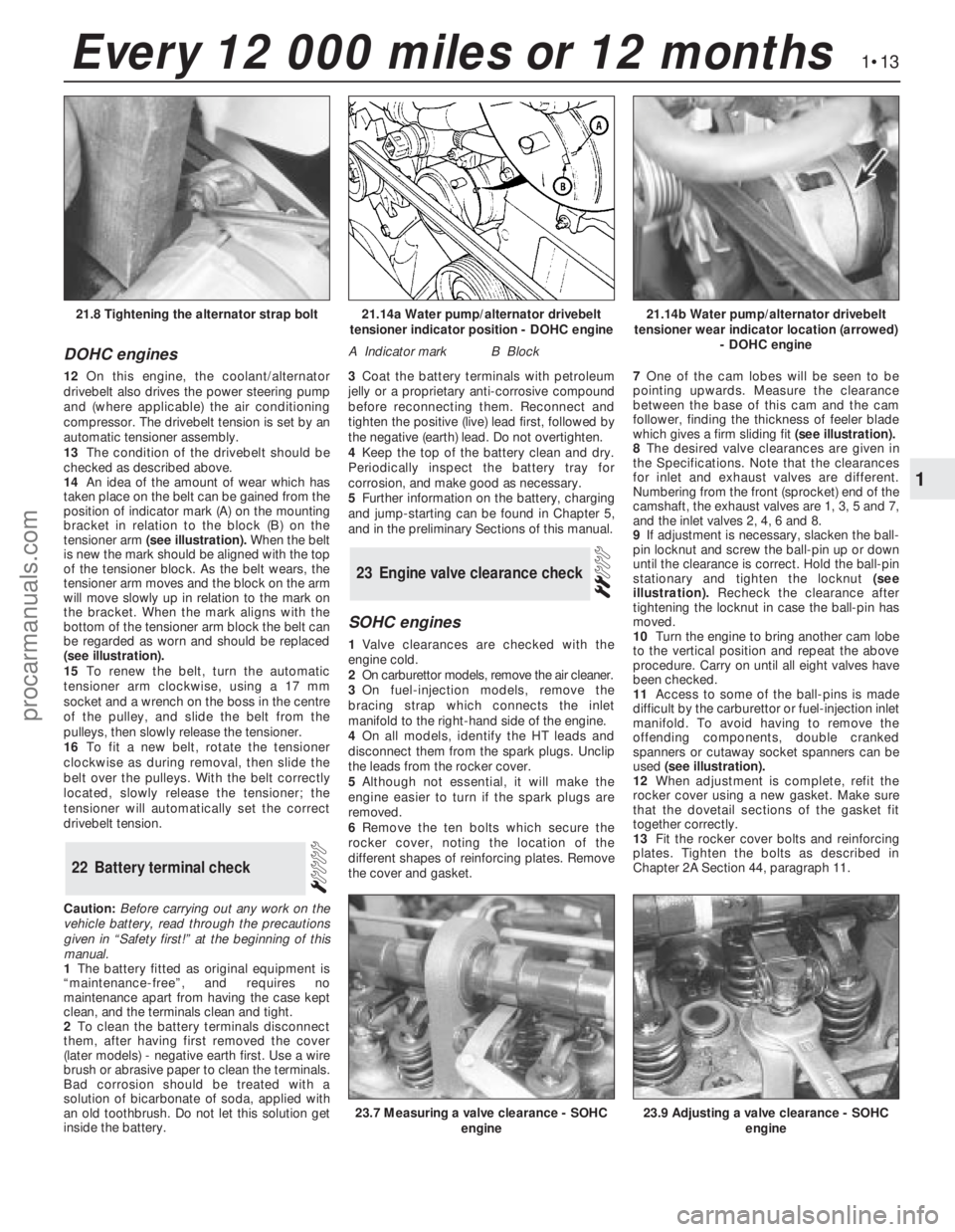
position of indicator mark (A) on the mounting
bracket in relation to the block (B) on the
tensioner arm (see illustration).When the belt
is new the mark should be aligned with the top
of the tensioner block. As the belt wears, the
tensioner arm moves and the block on the arm
will move slowly up in relation to the mark on
the bracket. When the mark aligns with the
bottom of the tensioner arm block the belt can
be regarded as worn and should be replaced
(see illustration).
15To renew the belt, turn the automatic
tensioner arm clockwise, using a 17 mm
socket and a wrench on the boss in the centre
of the pulley, and slide the belt from the
pulleys, then slowly release the tensioner.
16To fit a new belt, rotate the tensioner
clockwise as during removal, then slide the
belt over the pulleys. With the belt correctly
located, slowly release the tensioner; the
tensioner will automatically set the correct
drivebelt tension.
Caution:Before carrying out any work on the
vehicle battery, read through the precautions
given in “Safety first!” at the beginning of this
manual.
1The battery fitted as original equipment is
“maintenance-free”, and requires no
maintenance apart from having the case kept
clean, and the terminals clean and tight.
2To clean the battery terminals disconnect
them, after having first removed the cover
(later models) -negative earth first. Use a wire
brush or abrasive paper to clean the terminals.
Bad corrosion should be treated with a
solution of bicarbonate of soda, applied with
an old toothbrush. Do not let this solution get
inside the battery.3Coat the battery terminals with petroleum
jelly or a proprietary anti-corrosive compound
before reconnecting them. Reconnect and
tighten the positive (live) lead first, followed by
the negative (earth) lead. Do not overtighten.
4Keep the top of the battery clean and dry.
Periodically inspect the battery tray for
corrosion, and make good as necessary.
5Further information on the battery, charging
and jump-starting can be found in Chapter 5,
and in the preliminary Sections of this manual.
SOHC engines
1Valve clearances are checked with the
engine cold.
2On carburettor models, remove the air cleaner.
3On fuel-injection models, remove the
bracing strap which connects the inlet
manifold to the right-hand side of the engine.
4On all models, identify the HT leads and
disconnect them from the spark plugs. Unclip
the leads from the rocker cover.
5Although not essential, it will make the
engine easier to turn if the spark plugs are
removed.
6Remove the ten bolts which secure the
rocker cover, noting the location of the
different shapes of reinforcing plates. Remove
the cover and gasket.7One of the cam lobes will be seen to be
pointing upwards. Measure the clearance
between the base of this cam and the cam
follower, finding the thickness of feeler blade
which gives a firm sliding fit(see illustration).
8The desired valve clearances are given in
the Specifications. Note that the clearances
for inlet and exhaust valves are different.
Numbering from the front (sprocket) end of the
camshaft, the exhaust valves are 1, 3, 5 and 7,
and the inlet valves 2, 4, 6 and 8.
9If adjustment is necessary, slacken the ball-
pin locknut and screw the ball-pin up or down
until the clearance is correct. Hold the ball-pin
stationary and tighten the locknut(see
illustration).Recheck the clearance after
tightening the locknut in case the ball-pin has
moved.
10Turn the engine to bring another cam lobe
to the vertical position and repeat the above
procedure. Carry on until all eight valves have
been checked.
11Access to some of the ball-pins is made
difficult by the carburettor or fuel-injection inlet
manifold. To avoid having to remove the
offending components, double cranked
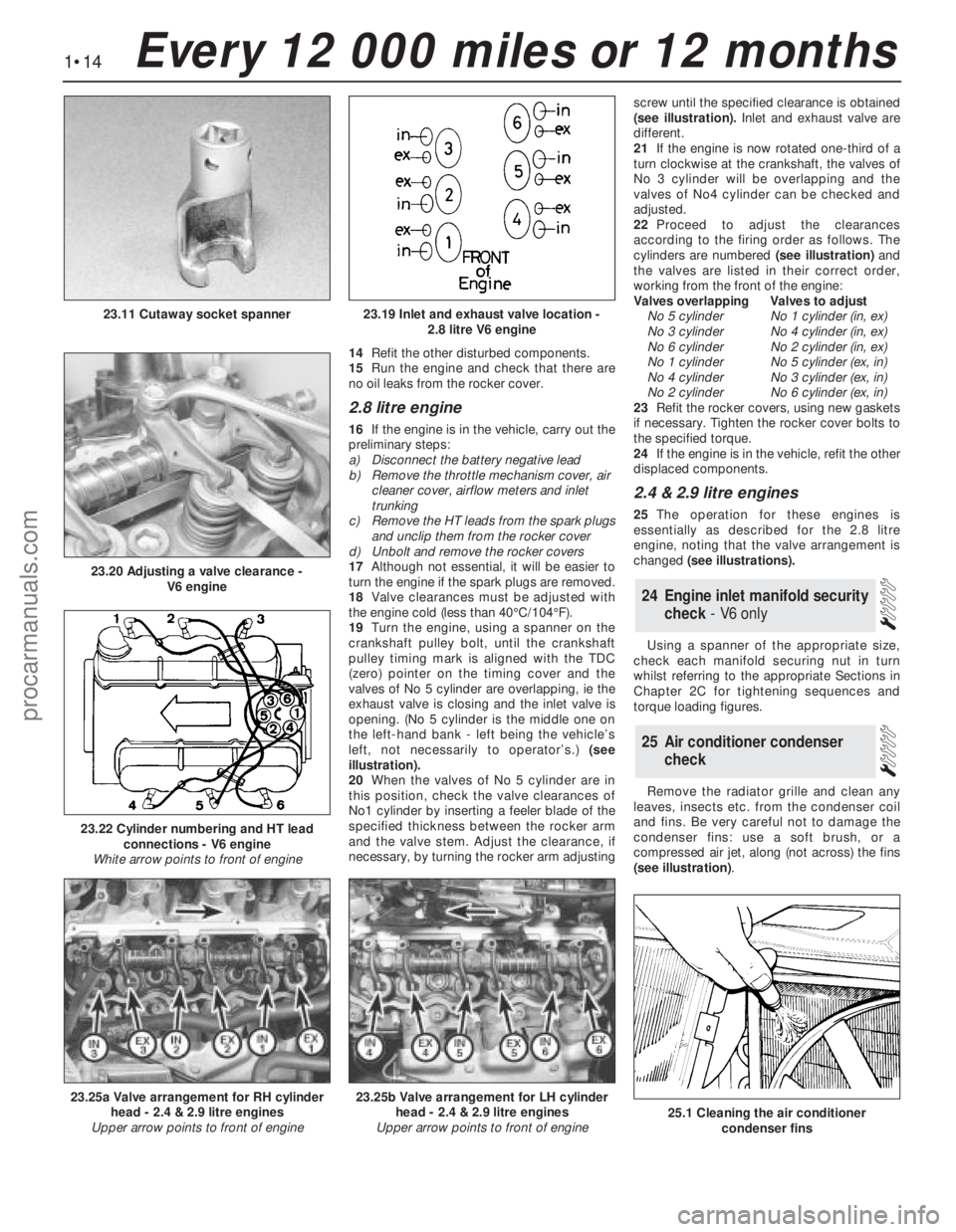
spanners or cutaway socket spanners can be
used (see illustration).
12When adjustment is complete, refit the
rocker cover using a new gasket. Make sure
that the dovetail sections of the gasket fit
together correctly.
13Fit the rocker cover bolts and reinforcing
plates. Tighten the bolts as described in
Chapter 2A Section 44, paragraph 11.
23Engine valve clearance check
22Battery terminal check
1•13
1
Every 12 000 miles or 12 months
21.14a Water pump/alternator drivebelt
tensioner indicator position - DOHC engine
A Indicator markB Block
21.14b Water pump/alternator drivebelt
tensioner wear indicator location (arrowed)
- DOHC engine21.8 Tightening the alternator strap bolt
23.7 Measuring a valve clearance - SOHC
engine23.9 Adjusting a valve clearance - SOHC
engine
procarmanuals.com
Page 15 of 255
14Refit the other disturbed components.
15Run the engine and check that there are
no oil leaks from the rocker cover.
2.8 litre engine
16If the engine is in the vehicle, carry out the
preliminary steps:
a)Disconnect the battery negative lead
b)Remove the throttle mechanism cover, air
cleaner cover, airflow meters and inlet
trunking
c)Remove the HT leads from the spark plugs
and unclip them from the rocker cover
d)Unbolt and remove the rocker covers
17Although not essential, it will be easier to
turn the engine if the spark plugs are removed.
18Valve clearances must be adjusted with
the engine cold (less than 40°C/104°F).
19Turn the engine, using a spanner on the
crankshaft pulley bolt, until the crankshaft
pulley timing mark is aligned with the TDC
(zero) pointer on the timing cover and the
valves of No 5 cylinder are overlapping, ie the
exhaust valve is closing and the inlet valve is
opening. (No 5 cylinder is the middle one on
the left-hand bank - left being the vehicle’s
left, not necessarily to operator’s.) (see
illustration).
20When the valves of No 5 cylinder are in
this position, check the valve clearances of
No1 cylinder by inserting a feeler blade of the
specified thickness between the rocker arm
and the valve stem. Adjust the clearance, if
necessary, by turning the rocker arm adjustingscrew until the specified clearance is obtained
(see illustration).Inlet and exhaust valve are
different.
21If the engine is now rotated one-third of a
turn clockwise at the crankshaft, the valves of
No 3 cylinder will be overlapping and the
valves of No4 cylinder can be checked and
adjusted.
22Proceed to adjust the clearances
according to the firing order as follows. The
cylinders are numbered (see illustration)and
the valves are listed in their correct order,
working from the front of the engine:
Valves overlappingValves to adjust
No 5 cylinderNo 1 cylinder (in, ex)
No 3 cylinderNo 4 cylinder (in, ex)
No 6 cylinderNo 2 cylinder (in, ex)
No 1 cylinderNo 5 cylinder (ex, in)
No 4 cylinderNo 3 cylinder (ex, in)
No 2 cylinderNo 6 cylinder (ex, in)
23Refit the rocker covers, using new gaskets
if necessary. Tighten the rocker cover bolts to
the specified torque.
24If the engine is in the vehicle, refit the other
displaced components.
2.4 & 2.9 litre engines
25The operation for these engines is
essentially as described for the 2.8 litre
engine, noting that the valve arrangement is
changed (see illustrations).
Using a spanner of the appropriate size,
check each manifold securing nut in turn
whilst referring to the appropriate Sections in
Chapter 2C for tightening sequences and
torque loading figures.
Remove the radiator grille and clean any
leaves, insects etc. from the condenser coil
and fins. Be very careful not to damage the
condenser fins: use a soft brush, or a
compressed air jet, along (not across) the fins
(see illustration).
25Air conditioner condenser
check
24Engine inlet manifold security
check - V6 only
1•14Every 12 000 miles or 12 months
23.19 Inlet and exhaust valve location -
2.8 litre V6 engine
23.20 Adjusting a valve clearance -
V6 engine
23.11 Cutaway socket spanner
23.25a Valve arrangement for RH cylinder
head - 2.4 & 2.9 litre engines
Upper arrow points to front of engine23.25b Valve arrangement for LH cylinder
head - 2.4 & 2.9 litre engines
Upper arrow points to front of engine
23.22 Cylinder numbering and HT lead
connections - V6 engine
White arrow points to front of engine
25.1 Cleaning the air conditioner
condenser fins
procarmanuals.com
Page 18 of 255
DOHC engine
8Proceed as described above whilst noting
that the camshaft cover breather hose must
be disconnected before the air cleaner can be
removed.
Fuel-injection models
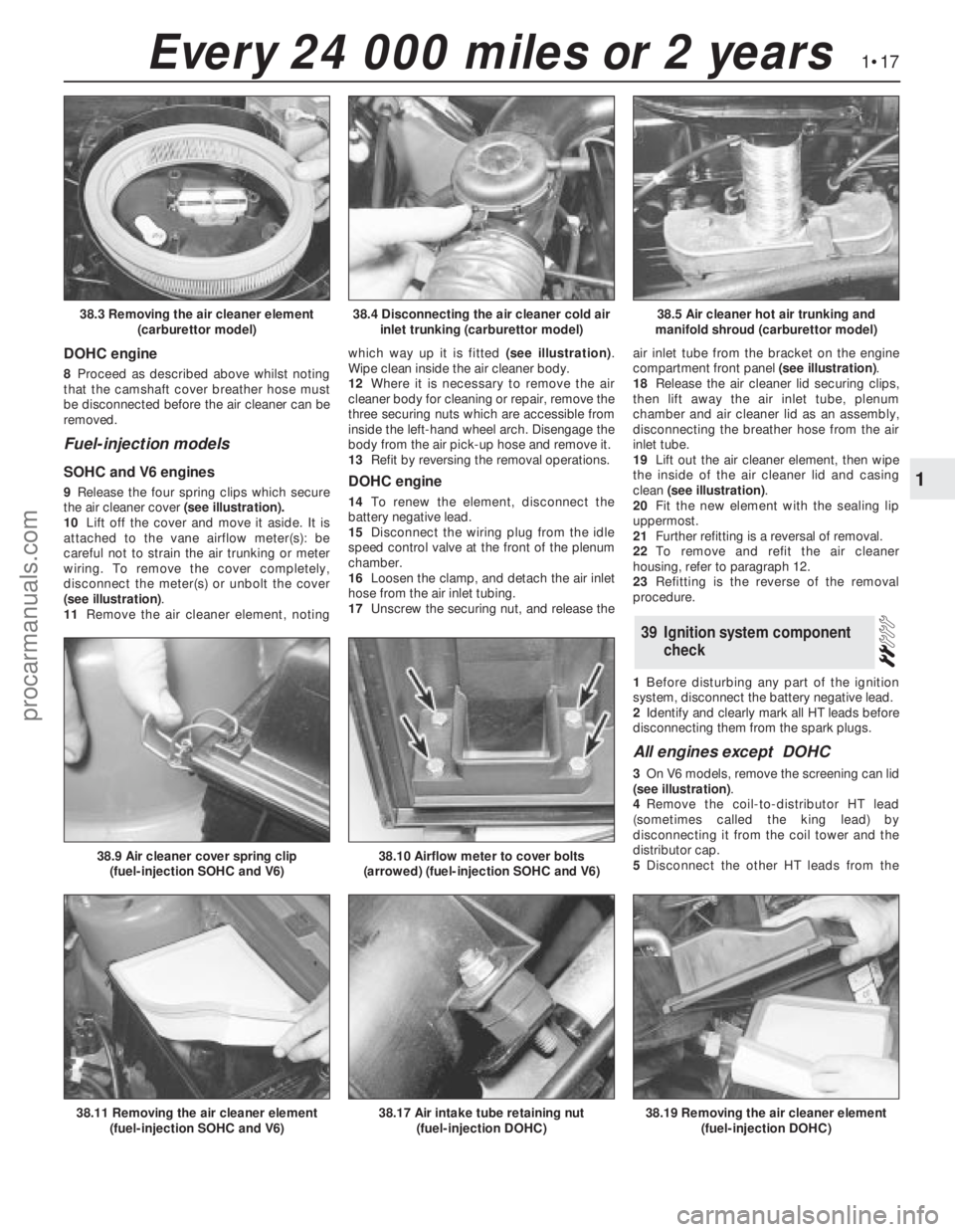
SOHC and V6 engines
9Release the four spring clips which secure
the air cleaner cover(see illustration).
10Lift off the cover and move it aside. It is
attached to the vane airflow meter(s): be
careful not to strain the air trunking or meter
wiring. To remove the cover completely,
disconnect the meter(s) or unbolt the cover
(see illustration).
11Remove the air cleaner element, notingwhich way up it is fitted (see illustration).
Wipe clean inside the air cleaner body.
12Where it is necessary to remove the air
cleaner body for cleaning or repair, remove the
three securing nuts which are accessible from
inside the left-hand wheel arch. Disengage the
body from the air pick-up hose and remove it.
13Refit by reversing the removal operations.DOHC engine
14To renewthe element, disconnect the
battery negative lead.
15Disconnect the wiring plug from the idle
speed control valve at the front of the plenum
chamber.
16Loosen the clamp, and detach the air inlet
hose from the air inlet tubing.
17Unscrew the securing nut, and release theair inlet tube from the bracket on the engine
compartment front panel (see illustration).
18Release the air cleaner lid securing clips,
then lift away the air inlet tube, plenum
chamber and air cleaner lid as an assembly,
disconnecting the breather hose from the air
inlet tube.
19Lift out the air cleaner element, then wipe
the inside of the air cleaner lid and casing
clean (see illustration).
20Fit the new element with the sealing lip
uppermost.
21Further refitting is a reversal of removal.
22To remove and refit the air cleaner
housing, refer to paragraph 12.
23Refitting is the reverse of the removal
procedure.
1Before disturbing any part of the ignition
system, disconnect the battery negative lead.
2Identify and clearly mark all HT leads before
disconnecting them from the spark plugs.
All engines except DOHC
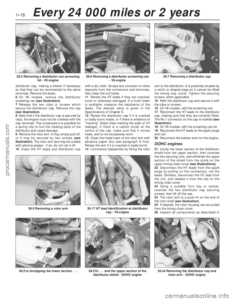
3On V6 models, remove the screening can lid
(see illustration).
4Remove the coil-to-distributor HT lead
(sometimes called the king lead) by
disconnecting it from the coil tower and the
distributor cap.
5Disconnect the other HT leads from the
39Ignition system component
check
1•17
1
Every 24 000 miles or 2 years
38.4 Disconnecting the air cleaner cold air
inlet trunking (carburettor model)38.5 Air cleaner hot air trunking and
manifold shroud (carburettor model)38.3 Removing the air cleaner element
(carburettor model)
38.17 Air intake tube retaining nut
(fuel-injection DOHC)38.19 Removing the air cleaner element
(fuel-injection DOHC)38.11 Removing the air cleaner element
(fuel-injection SOHC and V6)
38.9 Air cleaner cover spring clip
(fuel-injection SOHC and V6)38.10 Airflow meter to cover bolts
(arrowed) (fuel-injection SOHC and V6)
procarmanuals.com
Page 19 of 255
distributor cap, making a sketch if necessary
so that they can be reconnected to the same
terminals. Remove the leads.
6On V6 models, remove the distributor
screening can (see illustration).
7Release the two clips or screws which
secure the distributor cap. Remove the cap
(see illustration).
8Note that if the distributor cap is secured by
clips, the engine must not be cranked with the
cap removed. This is because it is possible for
a spring clip to foul the rotating parts of the
distributor and cause damage.
9Remove the rotor arm. It may simply pull off,
or it may be secured by two screws (see
illustration). The rotor arm tips may be coated
with silicone grease - if so, do not rub it off.
10Clean the HT leads and distributor capwith a dry cloth. Scrape any corrosion or other
deposits from the connectors and terminals.
Also clean the coil tower.
11Renew the HT leads if they are cracked,
burnt or otherwise damaged. If a multi-meter
is available, measure the resistance of the
leads. The desired value is given in the
Specifications of Chapter 5.
12Renew the distributor cap if it is cracked
or badly burnt inside, or if there is evidence of
“tracking” (black lines marking the path of HT
leakage). If there is a carbon brush at the
centre of the cap, make sure that it moves
freely, and is not excessively worn.
13Clean the metal track of the rotor arm with
abrasive paper (but see paragraph 9 first).
Renew the arm if it is cracked or badly burnt.
14Commence reassembly by fitting the rotorarm to the distributor. It is positively located by
a notch or shaped pegs so it cannot be fitted
the wrong way round. Tighten the securing
screws, when applicable.
15Refit the distributor cap and secure it with
the clips or screws.
16On V6 models, refit the screening can.
17Reconnect the HT leads to the distributor
cap, making sure that they are correctly fitted.
The No 1 connector on the cap is marked (see
illustration).
18On V6 models, refit the screening can lid.
19Reconnect the HT leads to the spark plugs
and coil.
20Reconnect the battery and run the engine.
DOHC engines
21Unclip the lower section of the distributor
shield from the upper section, then unscrew
the two securing nuts, and withdraw the upper
section of the shield from the studs on the
upper timing chain cover (see illustrations).
22Disconnect the HT leads from the spark
plugs by pulling on the connectors, not the
leads. Similarly, disconnect the HT lead from
the coil, and release it from the clip on the
timing chain cover.
23Using a suitable Torx key or socket,
unscrew the two distributor cap securing
screws, then lift off the cap.
24The rotor arm is a push-fit on the end of
the rotor shaft (see illustration).
25If desired, the rotor housing can be pulled
from the timing chain cover.
26Inspect all components as described in
1•18Every 24 000 miles or 2 years
39.6 Removing a distributor screening can
- V6 engine39.7 Removing a distributor cap39.3 Removing a distributor can screening
lid - V6 engine
39.21b . . . and the upper section of the
distributor shield - DOHC engine39.24 Removing the distributor cap and
rotor arm - DOHC engine39.21a Unclipping the lower section . . .
39.9 Removing a rotor arm39.17 HT lead identification at distributor
cap - V6 engine
procarmanuals.com
Page 22 of 255
Engine
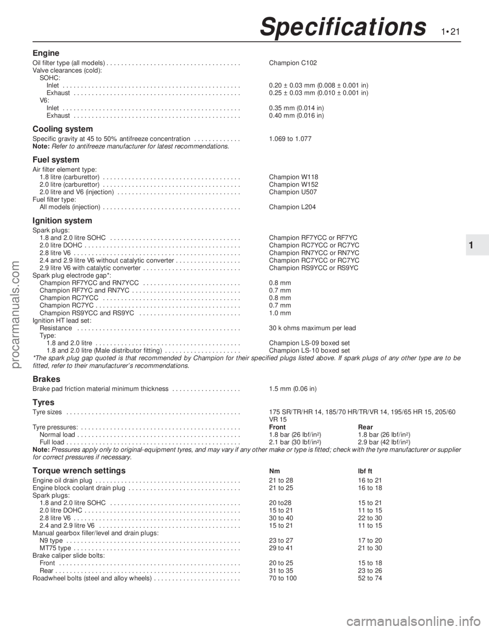
Oil filter type (all models) . . . . . . . . . . . . . . . . . . . . . . . . . . . . . . . . . . . . .Champion C102
Valve clearances (cold):
SOHC:
Inlet . . . . . . . . . . . . . . . . . . . . . . . . . . . . . . . . . . . . . . . . . . . . . . . . .0.20 ±0.03 mm (0.008 ±0.001 in)
Exhaust . . . . . . . . . . . . . . . . . . . . . . . . . . . . . . . . . . . . . . . . . . . . . .0.25 ±0.03 mm (0.010 ±0.001 in)
V6:
Inlet . . . . . . . . . . . . . . . . . . . . . . . . . . . . . . . . . . . . . . . . . . . . . . . . .0.35 mm (0.014 in)
Exhaust . . . . . . . . . . . . . . . . . . . . . . . . . . . . . . . . . . . . . . . . . . . . . .0.40 mm (0.016 in)
Cooling system
Specific gravity at 45 to 50% antifreeze concentration . . . . . . . . . . . . .1.069 to 1.077
Note:Refer to antifreeze manufacturer for latest recommendations.
Fuel system
Air filter element type:
1.8 litre (carburettor) . . . . . . . . . . . . . . . . . . . . . . . . . . . . . . . . . . . . . .Champion W118
2.0 litre (carburettor) . . . . . . . . . . . . . . . . . . . . . . . . . . . . . . . . . . . . . .Champion W152
2.0 litre and V6 (injection) . . . . . . . . . . . . . . . . . . . . . . . . . . . . . . . . . .Champion U507
Fuel filter type:
All models (injection) . . . . . . . . . . . . . . . . . . . . . . . . . . . . . . . . . . . . . .Champion L204
Ignition system
Spark plugs:
1.8 and 2.0 litre SOHC . . . . . . . . . . . . . . . . . . . . . . . . . . . . . . . . . . . .Champion RF7YCC or RF7YC
2.0 litre DOHC . . . . . . . . . . . . . . . . . . . . . . . . . . . . . . . . . . . . . . . . . . .Champion RC7YCC or RC7YC
2.8 litre V6 . . . . . . . . . . . . . . . . . . . . . . . . . . . . . . . . . . . . . . . . . . . . . .Champion RN7YCC or RN7YC
2.4 and 2.9 litre V6 without catalytic converter . . . . . . . . . . . . . . . . . .Champion RC7YCC or RC7YC
2.9 litre V6 with catalytic converter . . . . . . . . . . . . . . . . . . . . . . . . . . .Champion RS9YCC or RS9YC
Spark plug electrode gap*:
Champion RF7YCC and RN7YCC . . . . . . . . . . . . . . . . . . . . . . . . . . .0.8 mm
Champion RF7YC and RN7YC . . . . . . . . . . . . . . . . . . . . . . . . . . . . . .0.7 mm
Champion RC7YCC . . . . . . . . . . . . . . . . . . . . . . . . . . . . . . . . . . . . . .0.8 mm
Champion RC7YC . . . . . . . . . . . . . . . . . . . . . . . . . . . . . . . . . . . . . . . .0.7 mm
Champion RS9YCC and RS9YC . . . . . . . . . . . . . . . . . . . . . . . . . . . .1.0 mm
Ignition HT lead set:
Resistance . . . . . . . . . . . . . . . . . . . . . . . . . . . . . . . . . . . . . . . . . . . . .30 k ohms maximum per lead
Type:
1.8 and 2.0 litre . . . . . . . . . . . . . . . . . . . . . . . . . . . . . . . . . . . . . . . .Champion LS-09 boxed set
1.8 and 2.0 litre (Male distributor fitting) . . . . . . . . . . . . . . . . . . . . .Champion LS-10 boxed set
*The spark plug gap quoted is that recommended by Champion for their specified plugs listed above. If spark plugs of any other type are to be
fitted, refer to their manufacturer’s recommendations.
Brakes
Brake pad friction material minimum thickness . . . . . . . . . . . . . . . . . . .1.5 mm (0.06 in)
Tyres
Tyre sizes . . . . . . . . . . . . . . . . . . . . . . . . . . . . . . . . . . . . . . . . . . . . . . . .175 SR/TR/HR 14, 185/70 HR/TR/VR 14,195/65 HR 15, 205/60
VR 15
Tyre pressures: . . . . . . . . . . . . . . . . . . . . . . . . . . . . . . . . . . . . . . . . . . . .FrontRear
Normal load . . . . . . . . . . . . . . . . . . . . . . . . . . . . . . . . . . . . . . . . . . . . .1.8 bar (26 lbf/in
2)1.8 bar (26 lbf/in2)
Full load . . . . . . . . . . . . . . . . . . . . . . . . . . . . . . . . . . . . . . . . . . . . . . . .2.1 bar (30 lbf/in2)2.9 bar (42 lbf/in2)
Note:Pressures apply only to original-equipment tyres, and may vary if any other make or type is fitted; check with the tyre manufacturer or supplier
for correct pressures if necessary.
Torque wrench settingsNmlbf ft
Engine oil drain plug . . . . . . . . . . . . . . . . . . . . . . . . . . . . . . . . . . . . . . . .21 to 2816 to 21
Engine block coolant drain plug . . . . . . . . . . . . . . . . . . . . . . . . . . . . . . .21 to 2516 to 18
Spark plugs:
1.8 and 2.0 litre SOHC . . . . . . . . . . . . . . . . . . . . . . . . . . . . . . . . . . . .20 to2815 to 21
2.0 litre DOHC . . . . . . . . . . . . . . . . . . . . . . . . . . . . . . . . . . . . . . . . . . .15 to 2111 to 15
2.8 litre V6 . . . . . . . . . . . . . . . . . . . . . . . . . . . . . . . . . . . . . . . . . . . . . .30 to 4022 to 30
2.4 and 2.9 litre V6 . . . . . . . . . . . . . . . . . . . . . . . . . . . . . . . . . . . . . . .15 to 2111 to 15
Manual gearbox filler/level and drain plugs:
N9 type . . . . . . . . . . . . . . . . . . . . . . . . . . . . . . . . . . . . . . . . . . . . . . . .23 to 2717 to 20
MT75 type . . . . . . . . . . . . . . . . . . . . . . . . . . . . . . . . . . . . . . . . . . . . . .29 to 4121 to 30
Brake caliper slide bolts:
Front . . . . . . . . . . . . . . . . . . . . . . . . . . . . . . . . . . . . . . . . . . . . . . . . . .20 to 2515 to 18
Rear . . . . . . . . . . . . . . . . . . . . . . . . . . . . . . . . . . . . . . . . . . . . . . . . . . .31 to 3523 to 26
Roadwheel bolts (steel and alloy wheels) . . . . . . . . . . . . . . . . . . . . . . . .70 to 10052 to 74
1•21
1
Specifications
procarmanuals.com