1982 CHEVROLET CAMARO wheel
[x] Cancel search: wheelPage 423 of 875

GM – CAMARO 1982-1992 – Repair Guide (Checked by WxMax) 423
22. Fill the engine with engine oil.
23. Start the engine and
check for leaks.
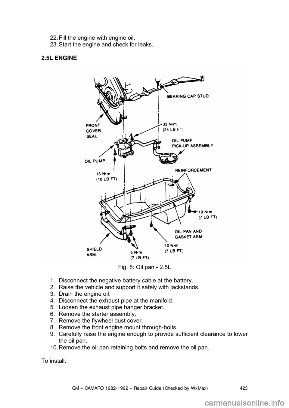
2.5L ENGINE
Fig. 8: Oil pan - 2.5L
1. Disconnect the negative batte ry cable at the battery.
2. Raise the vehicle and support it safely with jackstands.
3. Drain the engine oil.
4. Disconnect the exhaust pipe at the manifold.
5. Loosen the exhaust pipe hanger bracket.
6. Remove the starter assembly.
7. Remove the flywheel dust cover.
8. Remove the front engine mount through-bolts.
9. Carefully raise the engine enough to provide sufficient clearance to lower
the oil pan.
10. Remove the oil pan retaining bolts and remove the oil pan.
To install:
Page 424 of 875

GM – CAMARO 1982-1992 – Repair Guide (Checked by WxMax) 424
11. Clean all old RTV from the mating surfaces.
12. Install the rear gasket into the
rear main bearing cap and apply a small
amount of RTV where the gasket engages into the engine block.
13. Install the front gasket.
14. Install the side gaskets, using grease as a retainer. Apply a small amount
of RTV where the side gaskets meet the front gasket.
15. Install the oil pan.
Install the oil pan-to-timing cover bolts la st, as these holes will not align until the
other pan bolts are snug.
16. Torque the pan bolts to 53 inch lbs. (6 Nm) for 1982-1985 models and 90
inch lbs. (10 Nm) for 1986 models.
17. Lower the engine and install the fr ont mount through-bolts. Torque bolts
to 48 ft lbs. (65 Nm).
18. Install the flywheel dust cover.
19. Install the starter assembly.
20. Connect the exhaust pipe at the manifold.
21. Tighten the exhaust pipe hanger bracket.
22. Lower the vehicle.
23. Connect the negative battery cable at the battery.
24. Fill the engine with engine oil and start engine. Check for leaks.
OIL PUMP
REMOVAL & INSTALLATION
Fig. 1: Oil pump - V8
Page 442 of 875

GM – CAMARO 1982-1992 – Repair Guide (Checked by WxMax) 442
To install:
7. Lubricate all parts. Slide the ca mshaft onto the camshaft bearings.
8. Install the fuel pump and fuel pump pushrod.
9. Install the distributor and align all matchmarks.
10. Install the oil pump drive.
11. Install the valve lifters, pushrods and rocker arms.
12. Install the intake manifold and valve covers.
13. Install the timing and timing chain cover.
14. Install the radiator.
15. Fill the cooling syst em, start the engine and check for leaks.
BEARING
REMOVAL & INSTALLATION
It is recommended for a machine shop to perform these procedures.
To remove the camshaft bearings, the ca mshaft lifters, flywheel, rear camshaft
expansion plug, and cranks haft must be removed.
Camshaft bearings can be replaced wi th engine completely or partially
disassembled. To replace bearings without complete disassembly remove the
camshaft and crankshaft leaving cylinder heads attached and pistons in place.
Before removing crankshaft, tape threads of connecting rod bolts to prevent
damage to crankshaft. Fasten connecting rods against sides of engine so they
will not be in the way while replacing camshaft bearings.
If excessive wear is indicated, or if the engine is being completely rebuilt,
camshaft bearings should be replaced as follows: Drive the camshaft rear plug
from the block. Assemble the removal puller with its shoulder on the bearing to
be removed. Gradually tighten the puller nut until bearing is removed. Remove
remaining bearings, leaving the front and rear for last. To remove front and rear
bearings, reverse position of the tool, so as to pull the bearings in toward the
center of the block. Leave the tool in th is position, pilot the new front and rear
bearings on the installer, and pull them into position as follows:
• 4 cylinder engines: Ensure oil holes are properly aligned.
• V6 engines: Ensure the rear and intermediate bearing oil holes are
aligned between the 2 and 3 o'clock po sitions and the front bearing oil
holes are at 1:00 and between 2 and 3 o'clock positions.
• V8 engines: Ensure the No. 1 (f ront) camshaft bearing holes are an
equal distance from the 6 o'clock pos ition. The No. 2 through 4 inner
bearing holes must be posit ioned at the 5 o'clock position towards the left
side (drivers) of the engine, even wit h the bottom of the cylinder bore.
The No. 5 bearing oil holes must be positioned at 12 o'clock.
Return the tool to its original position and pull remaining bearings into position.
Page 451 of 875

GM – CAMARO 1982-1992 – Repair Guide (Checked by WxMax) 451
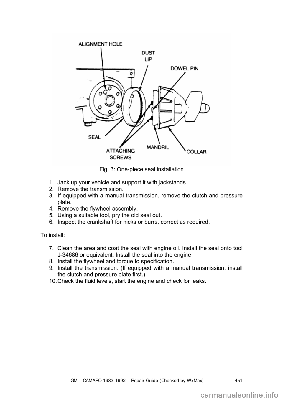
Fig. 3: One-piece seal installation
1. Jack up your vehicle and support it with jackstands.
2. Remove the transmission.
3. If equipped with a manual transmission, remove the clutch and pressure
plate.
4. Remove the flywheel assembly.
5. Using a suitable tool, pry the old seal out.
6. Inspect the crankshaft for nicks or burrs, correct as required.
To install: 7. Clean the area and coat the seal with eng ine oil. Install the seal onto tool
J-34686 or equivalent. Install the seal into the engine.
8. Install the flywheel and torque to specification.
9. Install the transmission. (If equipped with a manual transmission, install
the clutch and pressure plate first.)
10. Check the fluid levels, star t the engine and check for leaks.
Page 456 of 875

GM – CAMARO 1982-1992 – Repair Guide (Checked by WxMax) 456
2. Drain the engine oil and remove the oil pan.
3. Remove the rear main bearing cap.
4. Insert packing tool J-29114-2 or equi
valent, against 1 end of the seal in
the cylinder block. Drive the old seal gently into the groove until it is
packed tight. This will vary from
1/4 in. (6mm) to 3/4 in. (19mm) depending
on the amount of pack required.
5. Repeat the procedure on t he other end of the seal.
6. Measure the amount the seal wa s driven up on one side and add
1/16 in.
(1.6mm). Using a suitable cutting tool, cut that length from the old seal
removed from the rear main beari ng cap. Repeat the procedure for the
other side. Use the rear main bear ing cap as a holding fixture when
cutting the seal.
7. Install guide tool J-29114-1 or equi valent, onto the cylinder block.
8. Using the packing tool, work the shor t pieces cut in Step 6 into the guide
tool and then pack into the cylinder block. The guide tool and packing
tool are machined to provide a built in stop. Use this procedure for both
sides. It may help to use oil on the short pieces of the rope seal when \
packing them into the cylinder block.
9. Remove the guide tool.
10. Apply Loctite® 414 or equivalent, to the seal groove in the rear main
bearing cap. Within 1 minute, insert a new seal into the groove and push
into place with tool J-29590 until the seal is flush with the block. Cut the
excess seal material with a sharp cu tting tool at the bearing cap parting
line.
11. Apply a thin film of chassis grease to the rope se al. Apply a thin film of
RTV sealant on the bearing cap mati ng surface around the seal groove.
Use the sealer sparingly.
12. Plastigage® the rear main bea ring cap as outlined in MEASURING
REAR MAIN CLEARANCE in this section and check with specification. If
out of specification, check for fr ying of the rope seal which may be
causing the cap to not seat properly.
13. Install all remaining com ponents and inspect for leaks.
FLYWHEEL AND RING GEAR
REMOVAL & INSTALLATION
The ring gear is an integral part of the flywheel and is not replaceable.
1. Remove the transmission.
2. Remove the six bolts attaching t he flywheel to the crankshaft flange.
Remove the flywheel.
3. Inspect the flywheel for cracks, and inspect the ring gear for burrs or
worn teeth. Replace the flywheel if any damage is apparent. Remove
burrs with a mill file.
4. Install the flywheel. Th e flywheel will only attach to the crankshaft in one
position, as the bolt holes are unevenly spaced. Install the bolts and
torque to specification. Tighten bolts in crisscross pattern.
Page 476 of 875

GM – CAMARO 1982-1992 – Repair Guide (Checked by WxMax) 476
Before attempting to repair a threaded
hole, remove any snapped, broken or
damaged bolts or studs. Penetrating oil ca n be used to free frozen threads. The
offending item can usually be removed with locking pliers or using a screw/stud
extractor. After the hole is clear, the thread can be repaired, as shown in the
series of accompanying illustrations and in the kit manufacturer's instructions.
ENGINE PREPARATION
To properly rebuild an engine, you must fi rst remove it from the vehicle, then
disassemble and diagnose it. Ideally you should place your engine on an engine
stand. This affords you the best access to the engine components. Follow the
manufacturer's directions for using the stand with your particular engine.
Remove the flywheel or fl explate before installing the engine to the stand.
Now that you have the engine on a stand, and assuming that you have drained
the oil and coolant from the engine, it's ti me to strip it of all but the necessary
components. Before you start disassembli ng the engine, you may want to take
a moment to draw some pictures, or fabr icate some labels or containers to mark
the locations of various components and the bolts and/or studs which fasten
them. Modern day engines use a lot of littl e brackets and clips which hold wiring
harnesses and such, and these holders are often mounted on studs and/or bolts
that can be easily mixed up. The manufacturer spent a lot of time and money
designing your vehicle, and they wouldn't have wasted any of it by haphazardly
placing brackets, clips or fasteners on t he vehicle. If it's present when you
disassemble it, put it back when you asse mble, you will regret not remembering
that little bracket which holds a wire har ness out of the path of a rotating part.
You should begin by unbolting any accessories still attached to the engine, such
as the water pump, power steering pump, alternator, etc. Then, unfasten any
manifolds (intake or exhaust) which were not removed during the engine
removal procedure. Finally, remove any covers remaining on the engine such
as the rocker arm, front or timing cove r and oil pan. Some front covers may
require the vibration dam per and/or crank pulley to be removed beforehand.
The idea is to reduce the engine to the bar e necessities (cylinder head(s), valve
train, engine block, crankshaft, pistons and connecting rods), plus any other 'in
block' components such as oil pumps, balance shafts and auxiliary shafts.
Finally, remove the cylinder head(s) from the engine block and carefully place
on a bench. Disassembly instructions fo r each component follow later in this
section.
CYLINDER HEAD
There are two basic types of cylinder heads used on today’s automobiles:
the Overhead Valve (OHV) and the Over head Camshaft (OHC). The latter can
also be broken down into two subgr oups: the Single Overhead Camshaft
(SOHC) and the Dual Overhead Camshaft (DO HC). Generally, if there is only a
single camshaft on a head, it is just referred to as an OHC head. Also, an
engine with a OHV cylinder head is also known as a pushrod engine.
Page 492 of 875

GM – CAMARO 1982-1992 – Repair Guide (Checked by WxMax) 492
It is always recommended that you remo
ve any cylinder ridges before removing
the piston and connecting rod assemblies . If you know that new pistons are
going to be installed and the engine bl ock will be bored oversize, you may be
able to forego this step. However, some ridges may actually prevent the
assemblies from being remove d, necessitating its removal.
There are several different types of ridge reamers on the market, none of which
are inexpensive. Unless a great deal of engine rebuild ing is anticipated, borrow
or rent a reamer.
1. Turn the crankshaft until the piston is at the bottom of its travel.
2. Cover the head of the piston with a rag.
3. Follow the tool manufacturers in structions and cut away the ridge,
exercising extreme care to avoid cutting too deeply.
4. Remove the ridge reamer, the r ag and as many of the cuttings as
possible. Continue until all of the cylinder ridges have been removed.
DISASSEMBLY
The engine disassembly instructions fo llowing assume that you have the engine
mounted on an engine stand. If not, it is easiest to disassemble the engine on a
bench or the floor with it resting on t he bellhousing or transmission mounting
surface. You must be able to access the connecting rod fasteners and turn the
crankshaft during disassembly. Also, all en gine covers (timing, front, side, oil
pan, whatever) should have already been removed. Engines which are seized
or locked up may not be able to be co mpletely disassembled, and a core
(salvage yard) engine should be purchased.
If not done during the cylinder head removal, remove the pushrods and li\
fters,
keeping them in order for assembly. Remove the timing gears and/or timing
chain assembly, then remove the oil pu mp drive assembly and withdraw the
camshaft from the engine block. Remove the oil pick-up and pump assembly. If
equipped, remove any balanc e or auxiliary shafts. If necessary, remove the
cylinder ridge from the top of the bore. See the cylinder ridge removal
procedure earlier in this section.
Rotate the engine over so that the cr ankshaft is exposed. Use a number punch
or scribe and mark each connecting rod wit h its respective cylinder number. The
cylinder closest to the front of t he engine is always number 1. However,
depending on the engine placemen t, the front of the engine could either be the
flywheel or damper/pulley end. Generally the front of the engine faces the front
of the vehicle. Use a number punch or scribe and also mark the main bearing
caps from front to rear wit h the front most cap being nu mber 1 (if there are five
caps, mark them 1 through 5, front to rear).
Page 553 of 875

GM – CAMARO 1982-1992 – Repair Guide (Checked by WxMax) 553
If equipped with the 5.0L (VIN F) and 5.7L
(VIN 8) engines with Tuned Port
Injection (TPI), it will be necessary to remove the intake plenum to gain access
to the EGR valve.
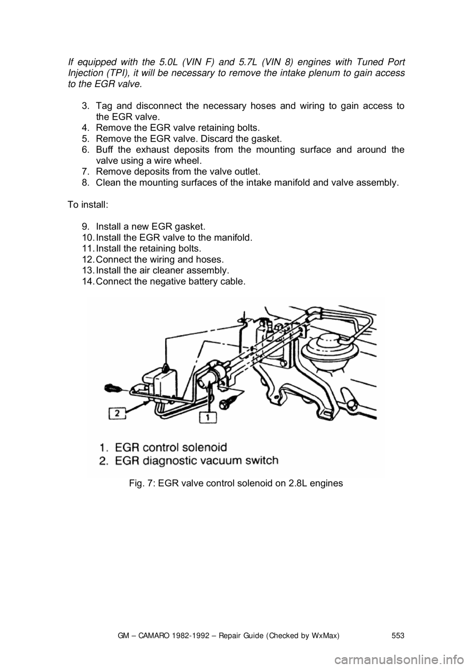
3. Tag and disconnect the necessary hos es and wiring to gain access to
the EGR valve.
4. Remove the EGR valve retaining bolts.
5. Remove the EGR valve. Discard the gasket.
6. Buff the exhaust deposits from the mounting surface and around the
valve using a wire wheel.
7. Remove deposits from the valve outlet.
8. Clean the mounting surfaces of the intake manifold and valve assembly.
To install: 9. Install a new EGR gasket.
10. Install the EGR valve to the manifold.
11. Install the retaining bolts.
12. Connect the wiring and hoses.
13. Install the air cleaner assembly.
14. Connect the negative battery cable.
Fig. 7: EGR valve control solenoid on 2.8L engines