1982 CHEVROLET CAMARO wheel
[x] Cancel search: wheelPage 641 of 875

GM – CAMARO 1982-1992 – Repair Guide (Checked by WxMax) 641
If, however, there is no spark or a weak
spark, then further ignition system
testing will have to be done. Troubleshooting techniques fall into various
categories, depending on t he nature of the problem and the system being
tested. Categories will include symptom s such as the engine cranks, but will not
start or the engine runs rough.
HEI SYSTEM
When testing the HEI system, there are 2 major categories of problems, (1)
Engine cranks, but will not star t or (2) Engine runs, but runs rough or cuts out.
If the engine will not start, perform a spar k test as described earlier. This will
narrow the problem area down considerab ly. If no spark occurs, check for the
presence of normal battery voltage at the battery ( BAT) terminal on the ignition
coil. The ignition switch must be in the ON position for this test. Either a
voltmeter or a test light wire may be us ed for this test. Connect the test light
wire to ground and the probe end to the BAT terminal at the coil. If the light
comes on, you have voltage to the distribut or and/or spark plug wires. If the light
fails to come on, this indicates an open circuit in the ignition primary wiring
leading to the distributor. In this case , you will have to check wiring continuity
back to the ignition switch using a test li ght. If there is battery voltage at the BAT
terminal, but no spark at the plugs, t hen the problem probably lies within the
distributor assembly.
If, on the other hand, the engine starts, but runs roughly or cuts out, make sure
the plug wires are in good shape first. There should be no obvious cracks or
breaks. You can check the plug wires with an ohmmeter, but do not pierce the
wires with a probe. Check the chart for th e correct plug wire resistance. If the
plug wires are OK, remove the cap asse mbly and check for moisture, cracks,
chips, or carbon tracks, or any other hi gh voltage leads or failures. Replace the
cap if any defects are found. Make su re the timer wheel rotates when the
engine is cranked.
If the trouble has been narrowed down to t he units within the distributor, the
following tests can help pinpoint the defective component. An ohmmeter with
both high and low ranges shou ld be used. These tests are made with the cap
assembly removed and the battery wir e disconnected. If a tachometer is
connected to the TACH terminal, disconnect it before making these tests.
IGNITION COIL
EXTERNALLY MOUNTED 1. Disconnect the coil wires and se t the ohmmeter on the high scale.
2. Connect the ohmmeter to the ignition co il as illustrated in Step 1 of the
accompanying figure.
3. The ohmmeter should read near infinite or very high.
Page 698 of 875

GM – CAMARO 1982-1992 – Repair Guide (Checked by WxMax) 698
5. Disconnect and plug hose to canister purge port.
6. Disconnect and plug hose to idle load compensator.
7. Back out idle stop screw
on carburetor 3 turns.
8. Turn air conditioning OFF.
9. Block drive wheels, set parki ng brake, place transmission in P, start and
warm engine to normal operating temperature. Make certain choke is
OPEN .
10. With engine RUNNING place transmission in D and idle load
compensator fully extended (no vacuum applied). Using tool J-29607, or
equivalent, adjust plunger to obtain 650-750 rpm. Locknut on plunger
must be held with a wrench to prevent damage to guide tabs.
11. Measure distance from the locknut to tip of the plunger. This distance
must not exceed 1 in. (25mm). If it does check for low idle condition.
12. Reconnect vacuum hose to idle load compensator and observe idle
speed.
13. Idle speed should be between 425-475 rpm in D.
14. If idle speed is correct no further adjustment is necessary, proceed to the
next step. If idle speed is still incorrect continue as follows:
It may be necessary to remove the idle load compensator from the engine
unless a hex key wrench is m odified to clear obstructions.
a. Stop engine, remove rubber cap from the center outlet tube.
b. Using a 0.90 in. (23mm) hex wrench, insert through open center tube to
engage idle speed adjusting screw.
c. If idle speed was low, turn t he adjusting screw counterclockwise
approximately 1 turn for every 85 rpm low. If idle speed was high turn
screw 1 turn for every 85 rpm high.
15. Disconnect and plug vacuum hose to the idle load compensator.
16. Using a hand pump, apply vacuum to the idle load compensator until fully
retracted.
17. Adjust the idle stop screw on carburetor float bowl to obtain 450 rpm in
D .
18. Place transmission in P and stop engine.
19. Reconnect the idle load compensator.
20. Reconnect all vacuum hoses.
21. Install air cleaner and gasket. Remove wheel blocks.
Page 732 of 875

GM – CAMARO 1982-1992 – Repair Guide (Checked by WxMax) 732
MINIMUM IDLE AND THROTTL
E VALVE SYNCHRONIZING
The throttle position of each throttle body must be balanced so that the throttle
plates are synchronized and open si multaneously. These adjustment
procedures must be followed AFTER performing the "Preliminary Adjustments".
1. Remove the air cleaner and plug the vacuum port on the rear TBI unit for
the thermostatic air cleaner.
2. Remove the tamper resistant pl ugs covering both unit throttle stop
screws, if necessary.
3. Block the drive wheels and apply the parking brake.
4. Connect a tachometer to measure rpm.
5. Start the engine and allo w the engine rpm to stabilize at normal operating
temperature.
6. Have a helper apply the brakes and place the transmission in DRIVE.
7. Plug the idle air pass ages of each throttle body with plugs (J-33047 or
equivalent). Make sure the plugs are seated fully in the passage so that
no air leaks exist. The engine rpm should decrease below curb idle
speed. If the engine rpm does not decreas e, check for a vacuum leak.
8. Remove the cap from the ported tube on the rear TBI unit and connect a
vacuum gauge or water manometer.
9. Adjust the rear unit throttle stop screw to obtain approximately
1/2 in. Hg
as read on the vacuum gauge, or 6 in. H
2O as read on the manometer. If
not able to adjust to this level, check that the front unit throttle stop is not
limiting throttle travel.
10. Remove the vacuum gauge or manometer from t he rear unit and install
the cap on the port ed vacuum tube.
11. Remove the cap from the ported va cuum tube on the front TBI unit and
install the gauge or manomet er as before. If the reading is not the same
as the rear unit, proceed as follows: a. Locate the throttle synchronizing screw and collar on the front TBI
unit. The screw may be welded to discourage tampering with this
adjustment. Break the weld, if ne cessary, and install a new screw
with a thread seali ng compound applied.
b. Adjust the screw to obtain approximately
1/2 in. Hg as read on the
vacuum gauge, or 6 in. H
2O on the manometer.
12. Remove the gauge or manometer fr om the ported tube and reinstall the
cap.
13. Adjust the rear throttle stop screw to obtain 475 rpm, with the
transmission in D and the parking brake applied. On manual
transmission models, leave the gear selector in N.
14. Turn the ignition OFF and pl ace automatic transmission in N.
15. Remove idle air passage plugs.
16. Start the engine. It may run at a high rpm but the engine speed should
decrease when the idle air control va lves close the air passages. Stop
the engine when the rpm decreases.
17. The throttle position sensor (TPS) voltage should be checked and adjusted, if necessary.
18. Connect the vacuum line to the TBI unit and install the air cleaner.
19. Reset the idle speed control motors by driving the vehicle to 45 mph.
Page 801 of 875

GM – CAMARO 1982-1992 – Repair Guide (Checked by WxMax) 801
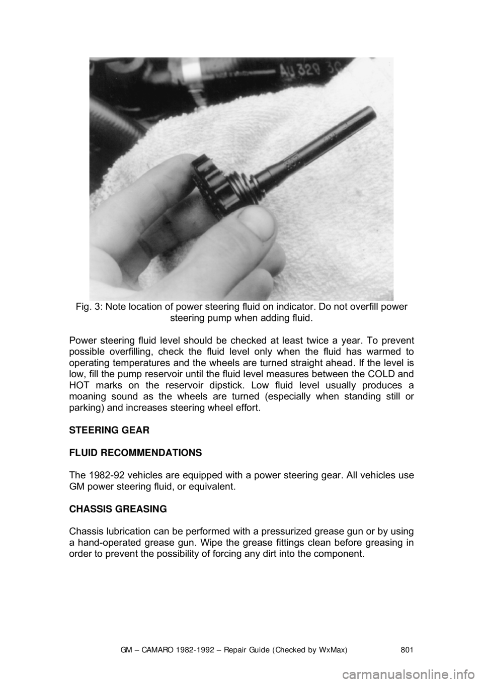
Fig. 3: Note location of power steering fluid on indicator. Do not overfill power
steering pump when adding fluid.
Power steering fluid level s hould be checked at least twice a year. To prevent
possible overfilling, check the fluid le vel only when the fluid has warmed to
operating temperatures and the wheels are turned straight ahead. If the level is
low, fill the pump reservoir until the flui d level measures between the COLD and
HOT marks on the reservoir dipstick. Low fluid level usually produces a
moaning sound as the wheels are turned (especially when standing still or
parking) and increases st eering wheel effort.
STEERING GEAR
FLUID RECOMMENDATIONS
The 1982-92 vehicles are equipped with a pow er steering gear. All vehicles use
GM power steering fluid, or equivalent.
CHASSIS GREASING
Chassis lubrication can be performed with a pressurized grease gun or by using
a hand-operated grease gun. Wipe the grease fittings clean before greasing in
order to prevent the possibility of fo rcing any dirt into the component.
Page 802 of 875

GM – CAMARO 1982-1992 – Repair Guide (Checked by WxMax) 802
BODY LUBRICATION
HOOD LATCH AND HINGES
Clean the latch surfaces and
apply clean engine oil to the latch pilot bolts and
the spring anchor. Use the engine oil to l ubricate the hood hinges as well. Use a
chassis grease to lubricate all the pivot points in the latch release mechanism.
DOOR HINGES
The gas tank filler door, car door, and rear hatch or trunk lid hinges should be
wiped clean and lubricated with clean engi ne oil. Silicone spray also works well
on seals, but must be applied more often. Use engine oil to lubricate the trunk
or hatch lock mechanism and the lock bo lt and striker. The door lock cylinders
can be lubricated easily with a shot of silicone spray or one of the many dry
penetrating lubricants commercially available.
PARKING BRAKE LINKAGE
Use chassis grease on the parking brake c able where it contacts the guides,
links, levers, and pulleys. The grease s hould be water resistant for durability.
ACCELERATOR LINKAGE
Lubricate the throttle lever, and the accele rator pedal lever at the support inside
the car with clean engine oil.
TRANSMISSION SHIFT LINKAGE
Lubricate the shift linkage with water re sistant chassis grease which meets GM
Specification 6031M or its equal.
FRONT WHEEL BEARINGS
Once every 30,000 miles, clean and repack wheel bearings with a wheel
bearing packer. Remove any excess grea se from the exposed surface of the
hub and seal.
REMOVAL, REPACKING, INSTA LLATION AND ADJUSTMENT
WARNING - It is important that wheel b earings be properly adjusted after
installation. Improperly adj usted wheel bearings can c ause steering instability,
front end shimmy and wander, and increased tire wear.
1. Raise the car and support it at the lower arm. Remove the tire and wheel
assembly.
2. Remove the brake caliper and support it on a wire.
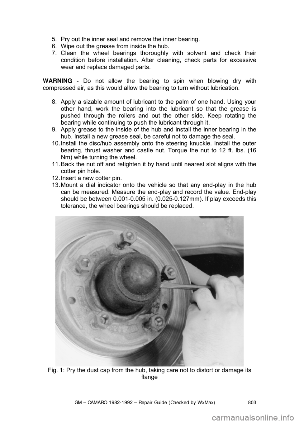
3. Remove the dust cap, cotter pin, ca stle nut, thrust washer and outside
wheel bearing.
4. Pull the disc/hub assembly from the steering knuckle.
Page 803 of 875

GM – CAMARO 1982-1992 – Repair Guide (Checked by WxMax) 803
5. Pry out the inner seal and
remove the inner bearing.
6. Wipe out the grease from inside the hub.
7. Clean the wheel bearings thor oughly with solvent and check their
condition before installation. Afte r cleaning, check parts for excessive
wear and replace damaged parts.
WARNING - Do not allow the bearing to spin when blowing dry with
compressed air, as this would allow t he bearing to turn without lubrication.
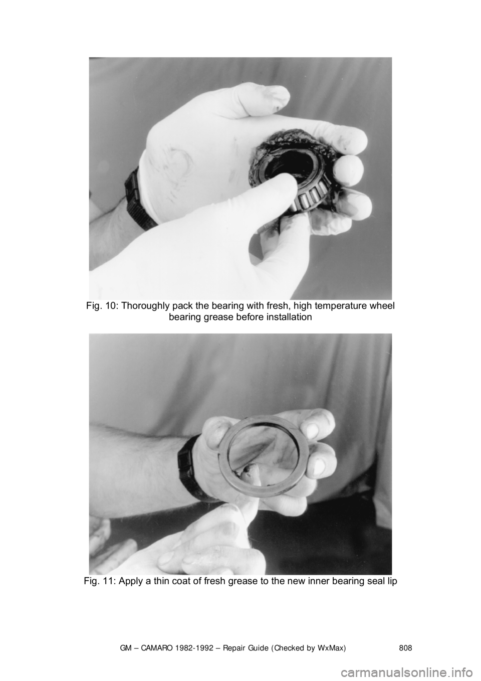
8. Apply a sizable amount of lubricant to the palm of one hand. Using your
other hand, work the bearing into the lubricant so that the grease is
pushed through the rollers and out t he other side. Keep rotating the
bearing while continuing to push the lubricant through it.
9. Apply grease to the inside of t he hub and install the inner bearing in the
hub. Install a new grease seal, be careful not to damage the seal.
10. Install the disc/hub assembly onto t he steering knuckle. Install the outer
bearing, thrust washer and castle nu t. Torque the nut to 12 ft. lbs. (16
Nm) while turning the wheel.
11. Back the nut off and retighten it by hand until nearest slot aligns with the
cotter pin hole.
12. Insert a new cotter pin.
13. Mount a dial indicator onto the vehi cle so that any end-play in the hub
can be measured. Measure the end-play and record the value. End-play
should be between 0.001-0.005 in. (0.025- 0.127mm). If play exceeds this
tolerance, the wheel bearings should be replaced.
Fig. 1: Pry the dust cap fr om the hub, taking care not to distort or damage its
flange
Page 808 of 875

GM – CAMARO 1982-1992 – Repair Guide (Checked by WxMax) 808
Fig. 10: Thoroughly pack the bearing wit h fresh, high temperature wheel
bearing grease before installation
Fig. 11: Apply a thin coat of fresh grease to the new inner bearing seal lip
Page 812 of 875

GM – CAMARO 1982-1992 – Repair Guide (Checked by WxMax) 812
9. Connect one end of the other jumper
cable to the negative (-) terminal on
the booster battery and the final cable clamp to an engine bolt head,
alternator bracket or ot her solid, metallic point on the engine with the
dead battery. Try to pick a ground on the engine that is positioned away
from the battery in order to minimi ze the possibility of the 2 clamps
touching should one l oosen during the procedure. DO NOT connect this
clamp to the negative (-) term inal of the bad battery.
CAUTION - Be very careful to keep the jum per cables away from moving parts
(cooling fan, belts, etc.) on both engines.
10. Check to make sure that the c ables are routed away from any moving
parts, then start the d onor vehicle's engine. Run the engine at moderate
speed for several minutes to allow the dead battery a chance to receive
some initial charge.
11. With the donor vehicle's engine still r unning slightly above idle, try to start
the vehicle with the dead battery. Crank the engine for no more than 10 \
seconds at a time and let the starter cool for at least 20 seconds between
tries. If the vehicl e does not start in 3 tries, it is likely that something else
is also wrong or that the battery needs additional time to charge.
12. Once the vehicle is star ted, allow it to run at idle for a few seconds to
make sure that it is operating properly.
13. Turn ON the headlight s, heater blower and, if equipped, the rear
defroster of both vehicles in order to reduce the severity of voltage spikes
and subsequent risk of dam age to the vehicles' electrical systems when
the cables are disconnected. This st ep is especially important to any
vehicle equipped with computer control modules.
14. Carefully disconnect the cables in the reverse order of connection. Star\
t with the negative cable that is attached to the engine ground, then the
negative cable on the donor battery. Di sconnect the positive cable from
the donor battery and finally, disconnect the positive cable from the
formerly dead battery. Be careful when disconnecting the cables from the
positive terminals not to allow the alli gator clips to touch any metal on
either vehicle or a short and sparks will occur.
JACKING
Your vehicle was supplied with a jack for emergency road repairs. This jack is
fine for changing a flat tire or other s hort term procedures not requiring you to
go beneath the vehicle. If it is used in an emergency situation, carefully follow
the instructions provided eit her with the jack or in your owner's manual. Do not
attempt to use the jack on any portions of the vehicle other than specified by the
vehicle manufacturer. Always block the diagonally opposite wheel when using a
jack.
A more convenient way of jacking is the use of a garage or floor jack. You may
use the floor jack to raise the vehicle in the areas shown in the illustration .