1982 CHEVROLET CAMARO wheel
[x] Cancel search: wheelPage 837 of 875

GM – CAMARO 1982-1992 – Repair Guide (Checked by WxMax) 837
1. Loosen the clamp bolts at each end
of the steering tie rod adjustable
sleeves.
2. With the steering wheel set strai ght ahead, turn the adjusting sleeves to
obtain the proper adjustment.
3. When the adjustment has been completed, check to see that the number
of threads showing on each end of the sleeve are equal. Also check that
tie rod end housings are at the right angles to the steering arm.
Page 845 of 875

GM – CAMARO 1982-1992 – Repair Guide (Checked by WxMax) 845
STABILIZER (SWAY) BAR
REMOVAL & INSTALLATION
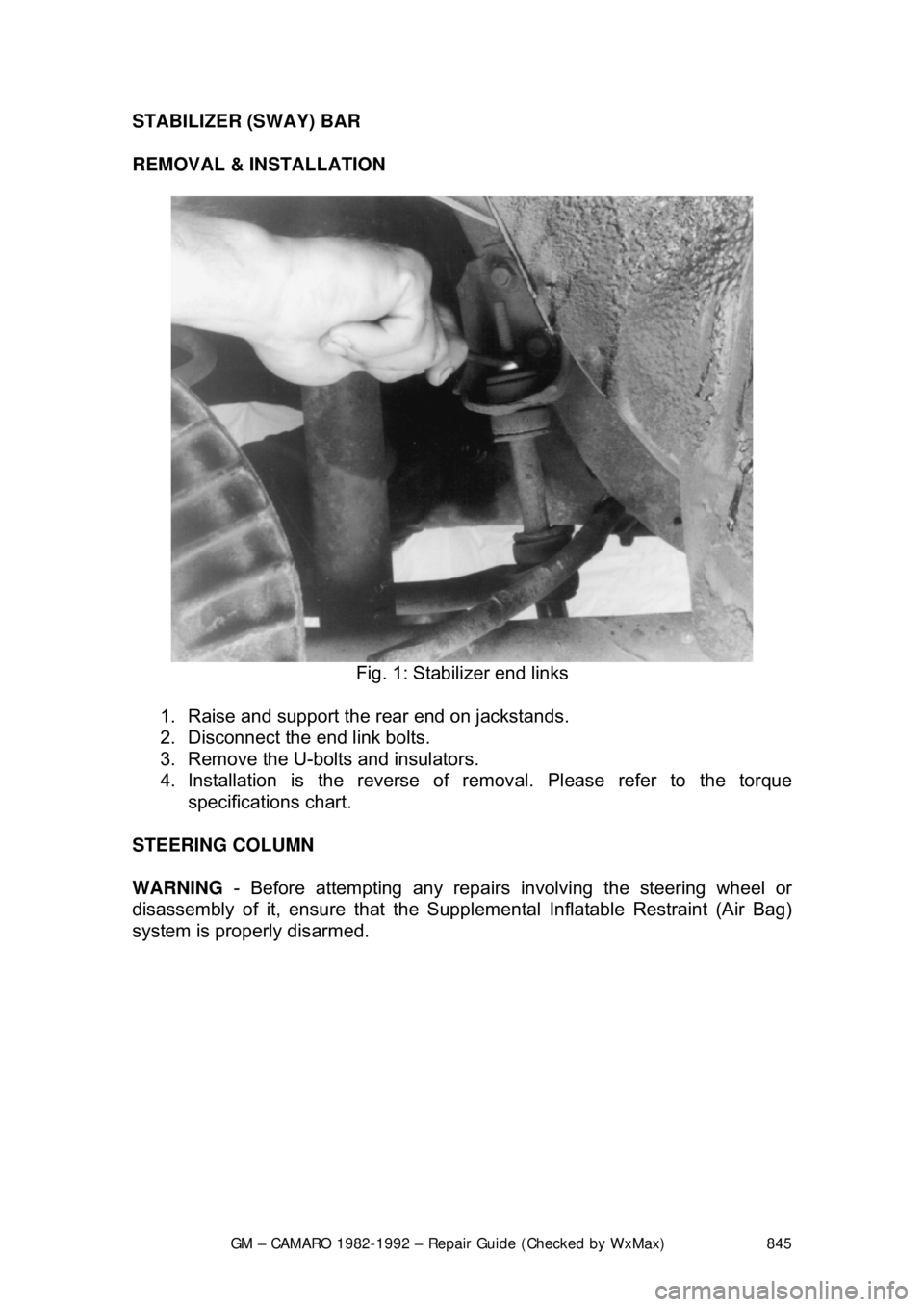
Fig. 1: Stabilizer end links
1. Raise and support the rear end on jackstands.
2. Disconnect the end link bolts.
3. Remove the U-bolts and insulators.
4. Installation is the reverse of re moval. Please refer to the torque
specifications chart.
STEERING COLUMN
WARNING - Before attempting any repairs involving the steering wheel or
disassembly of it, ensure that the Supple mental Inflatable Restraint (Air Bag)
system is properly disarmed.
Page 846 of 875

GM – CAMARO 1982-1992 – Repair Guide (Checked by WxMax) 846
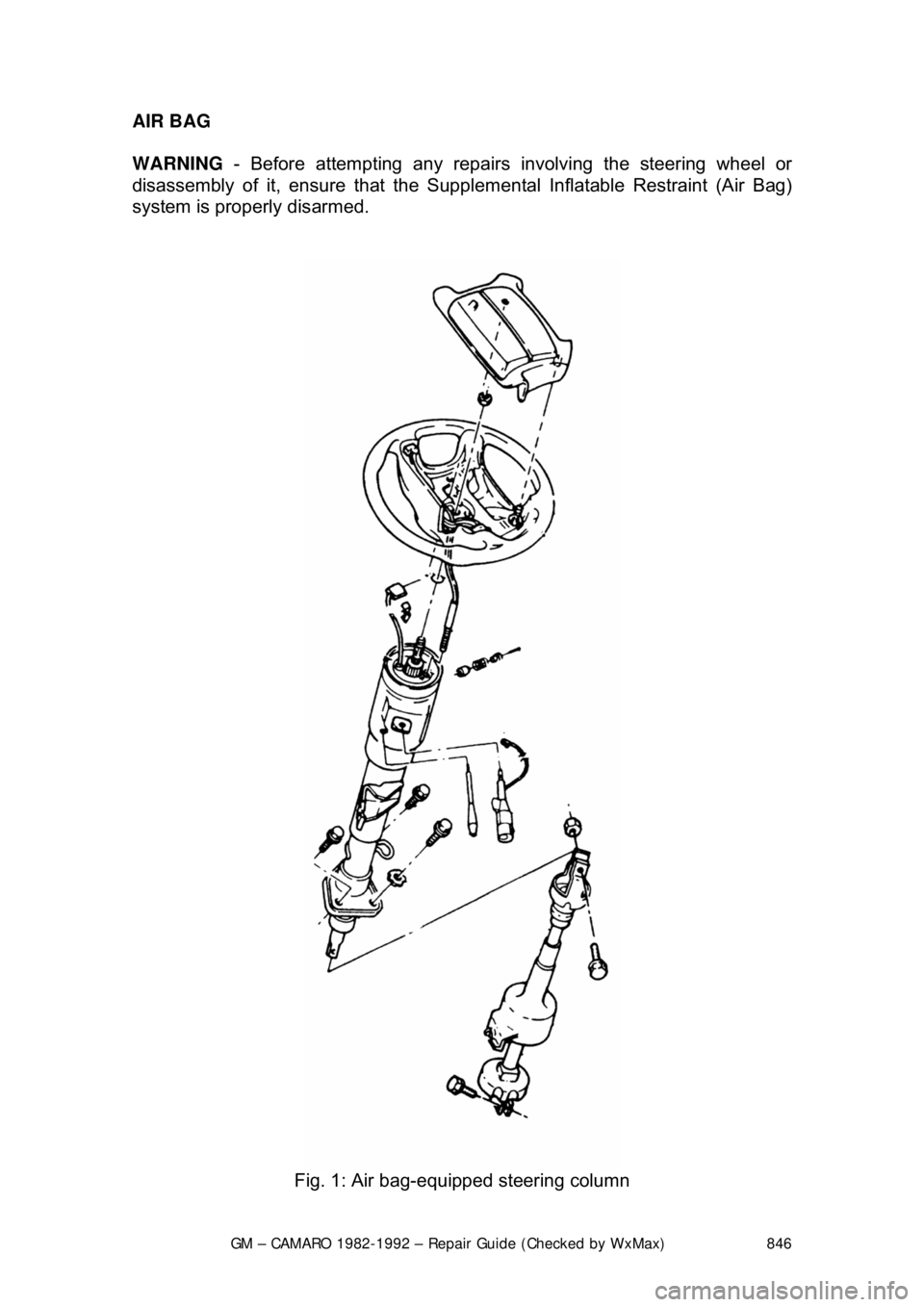
AIR BAG
WARNING
- Before attempting any repairs involving the steering wheel or
disassembly of it, ensure that the Supple mental Inflatable Restraint (Air Bag)
system is properly disarmed.
Fig. 1: Air bag-equipped steering column
Page 847 of 875

GM – CAMARO 1982-1992 – Repair Guide (Checked by WxMax) 847
DISARMING
1. Turn the steering wheel to align the w heels in the straight-ahead position.
2. Turn the ignition switch to the LOCK position.
3. Remove the SIR air bag fuse from the fuse block.
4. Remove the left side trim panel and disconnect the yellow 2-way SIR
harness wire connector at the bas e of the steering column.
To enable system: 5. Turn the ignition switch to the LOCK position.
6. Reconnect the yello w 2-way connector at the base of the steering
column.
7. Reinstall the SIR fuse and the left side trim panel.
8. Turn the ignition switch to the RUN position.
9. Verify the SIR indicator light flashes 7-9 times, if not as specified, inspect
system for malfunction or c ontact the manufacturer.
For more details on the SIR system - including disarming instructions for
passenger bags - please refer to Chassis Electrical in this repair guide.
SUPPLEMENTAL INFLATABLE REST RAINT (SIR) COIL ASSEMBLY
After performing repairs on the inter nals of the steering column the coil
assembly must be centered in order to avoid damaging the coil or accidental
deployment of the air bag. There are 2 different styles of coils, one rotates
clockwise and the other rotates counterclockwise.
ADJUSTMENT (CENTERING THE COIL) 1. With the system properly disarmed, hold the coil assembly with the clear
bottom up to see the coil ribbon.
2. While holding the coil assembly, depr ess the lock spring and rotate the
hub in the direction of the arrow until it stops. The coil should now be
wound up snug against the center hub.
3. Rotate the coil assembly in the opposite direction approximately 2
1/2
turns and release the lock spring between the locking tabs in front of the
arrow.
4. Install the coil assembly onto the steering shaft.
STEERING WHEEL
WARNING - Before attempting any repairs involving the steering wheel or
disassembly of it, ensure that the Supple mental Inflatable Restraint (Air Bag)
system is properly disarmed.
REMOVAL & INSTALLATION
If the vehicle is equipped with a SIR (A ir Bag) system, ensure that the proper
disarming procedure is followed.
Page 848 of 875

GM – CAMARO 1982-1992 – Repair Guide (Checked by WxMax) 848
1982-89 VEHICLES
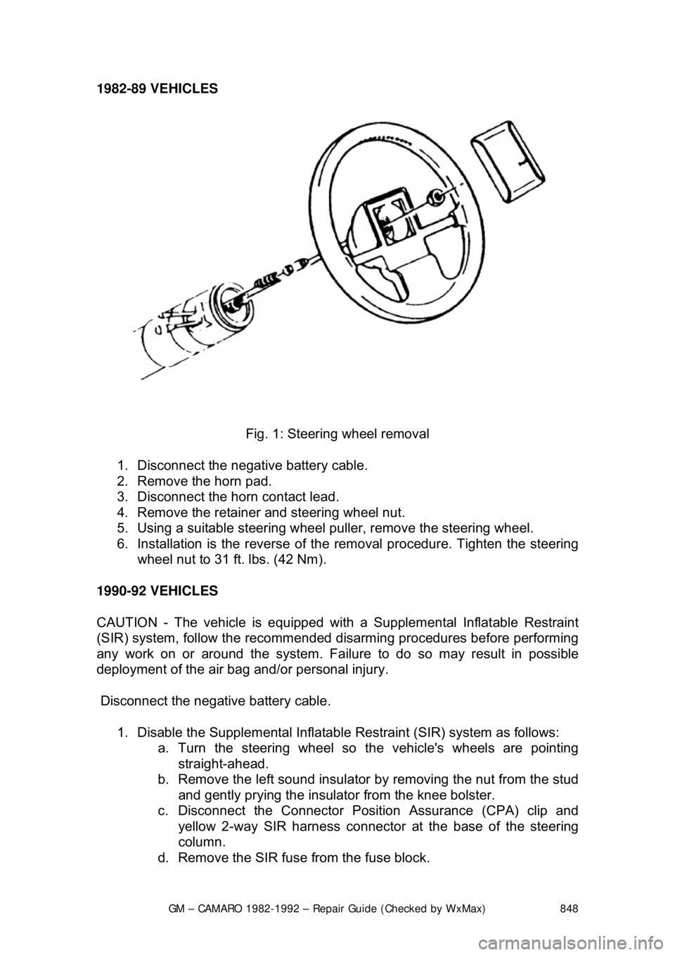
Fig. 1: Steering wheel removal
1. Disconnect the negative battery cable.
2. Remove the horn pad.
3. Disconnect the horn contact lead.
4. Remove the retainer and steering wheel nut.
5. Using a suitable steering wheel pu ller, remove the steering wheel.
6. Installation is the reverse of the removal procedure. Tighten the steering
wheel nut to 31 ft. lbs. (42 Nm).
1990-92 VEHICLES
CAUTION - The vehicle is equipped with a Supplemental Inflatable Restraint
(SIR) system, follow the recommended disarming procedures before performing
any work on or around the system. Failure to do so may result in possibl\
e
deployment of the air bag and/or personal injury.
Disconnect the negative battery cable.
1. Disable the Supplemental Inflatable Restraint (SIR) system as follows:
a. Turn the steering wheel so th e vehicle's wheels are pointing
straight-ahead.
b. Remove the left sound insulator by removing the nut from the stud
and gently prying the insulator from the knee bolster.
c. Disconnect the Connector Position Assurance (CPA) clip and yellow 2-way SIR harness connecto r at the base of the steering
column.
d. Remove the SIR fuse from the fuse block.
Page 849 of 875

GM – CAMARO 1982-1992 – Repair Guide (Checked by WxMax) 849
2. Loosen the screws and lo
cknuts from the back of the steering wheel
using a suitable Torx® driver or equi valent, until the inflator module can
be released from the steering wheel. Remove the inflator module from
the steering wheel.
CAUTION - When carrying a live inflator modul e, ensure the bag and trim cover
are pointed away from the body. In ca se of an accidental deployment, the bag
will then deploy with minima l chance of injury. When placing a live inflator
module on a bench or other surface, a lways place the bag and trim cover up,
away from the surface. This is necessa ry so a free space is provided to allow
the air bag to expand in the unlikely event of accidental deployment. Otherwise,
personal injury may result. Also, never carry the inflator module by the wires or
connector on the underside of the module.
4. Disconnect the coil assembly connec tor and CPA clip from the inflator
module terminal.
5. Remove the steering wheel locking nut.
6. Using a suitable pulle r, remove the steering wheel and disconnect the
horn contact. When attaching the steer ing wheel puller, use care to
prevent threading the side screws into the coil assembly and damaging
the coil assembly.
To install: 7. Route the coil assembly connec tor through the steering wheel.
8. Connect the horn contact and install the steering wheel. When installing
the steering wheel, ali gn the block tooth on the steering wheel with the
block tooth on the steering shaft within 1 female serration.
9. Install the steering wheel locking nu t. Tighten the nut to 31 ft. lbs. (42
Nm).
10. Connect the coil assembly connector and CPA clip to the inflator module
terminal.
11. Install the inflator module. Ensu re the wiring is not exposed or trapped
between the inflator modul e and the steering wheel. Tighten the inflator
module screws to 25 inch lbs. (2.8 Nm).
12. Connect the negative battery cable.
13. Enable the SIR system as follows: a. Connect the yellow 2-way SIR harness connector to base of the steering column and CPA.
b. Install the left sound insulator.
c. Install the SIR fuse in the fuse block.
d. Turn the ignition switch to the RUN position and verify that the
inflatable restraint indicator fl ashes 7-9 times and then turns OFF.
If the indicator does not respond as stated, a problem within the
SIR system is indicated.
Page 850 of 875

GM – CAMARO 1982-1992 – Repair Guide (Checked by WxMax) 850
TURN SIGNAL SWITCH
WARNING - Before attempting any repai
rs involving the steering wheel or
disassembly of it, ensure that the Supple mental Inflatable Restraint (Air Bag)
system is properly disarmed.
REMOVAL & INSTALLATION
STANDARD COLUMNS WITHOUT AIR BAG 1. Remove the steering wheel as pr eviously outlined. Remove the trim
cover.
2. Pry the cover off, and lift the cover off the shaft.
3. Position the U-shaped lockplate co mpressing tool on the end of the
steering shaft and compress the lock plate by turning the shaft nut
clockwise. Pry the wire snapri ng out of the shaft groove.
4. Remove the tool and lift t he lockplate off the shaft.
5. Remove the canceling cam assembly and upper bearing preload spring from the shaft.
6. Remove the turn signal lever. Pu sh the flasher knob in and unscrew it.
On models equipped with a button and a knob, remove the button
retaining screw, then remove the button, spring, and knob.
7. Pull the switch connect or out the mast jacket and tape the upper part to
facilitate switch removal. Attach a l ong piece of wire to the turn signal
switch connector. When in stalling the turn signal switch, feed this wire
through the column first, and then use this wire to pull the switch
connector into position. On tilt wheel s, place the turn signal and shifter
housing in low position and remove the harness cover.
8. Remove the three switch mounting screws. Remove the switch by pulling
it straight up while guiding the wir ing harness cover through the column.
To install: 9. Install the replacement switch by working the connector and cover down
through the housing and under the bracket. On tilt models, the connector
is worked down through the housing, under the bracket, and then the
cover is installed on the harness.
10. Install the switch mounting screw s and the connector on the mast jacket
bracket. Install the column -to-dash trim plate.
11. Install the flasher knob and the turn signal lever.
12. With the turn signal lever in neutral and the fl asher knob out, slide the
upper bearing preload spring, and canc eling cam assembly onto the
shaft.
13. Position the lock plate on the s haft and press it down until a new
snapring can be inserted in the shaft groove. Always use a new snapring
when assembling.
14. Install the cover and the steering wheel.
Page 852 of 875

GM – CAMARO 1982-1992 – Repair Guide (Checked by WxMax) 852
13. Remove the two nuts fr
om the column support bracket while holding the
column in position. Remove the br acket assembly and wire protector
from the wiring, then l oosely install the support column bracket.
14. Tape the turn signal wires at the c onnector to keep them fit and parallel.
15. Carefully remove the turn signal switch and wiring from the column.
To install: 16. Carefully install the turn signal switch and wiring into the column.
17. Remove the tape from the turn signal wires.
18. Install the wire protecto r and, while holding the colu mn in position, install
the two nuts to the colu mn support bracket.
19. Connect the clip to the link and ti ghten the screw that holds the shift
indicator needle.
20. Install the four bolts which secure the bracket assembly to the jacket.
21. Connect the turn signal connector to the wiring harness and install the
lower trim cap to the instrument panel.
22. Install the switch attaching screws.
23. Install the turn signal lever and the hazard flasher knob.
24. Install the upper bear ing preload spring.
25. Install the lockplate and the canceling cam.
26. Press down on the lockplate and inst all the snapring to the shaft using a
new snapring.
27. Install the cover to t he steering column shaft.
28. Install the steering wheel.
29. Connect the battery cable.