1982 CHEVROLET CAMARO wheel
[x] Cancel search: wheelPage 122 of 875

GM – CAMARO 1982-1992 – Repair Guide (Checked by WxMax) 122
REAR DISC BRAKES
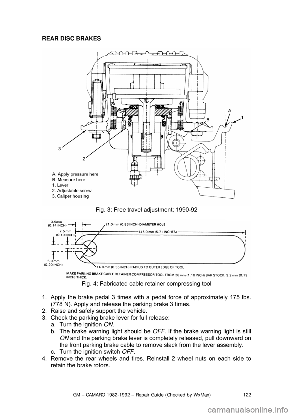
Fig. 3: Free trav el adjustment; 1990-92
Fig. 4: Fabricated cable retainer compressing tool
1. Apply the brake pedal 3 times with a pedal force of approximately 175 lbs.
(778 N). Apply and release t he parking brake 3 times.
2. Raise and safely support the vehicle.
3. Check the parking brake lever for full release: a. Turn the ignition ON.
b. The brake warning light should be OFF. If the brake warning light is still
ON and the parking brake lever is comple tely released, pull downward on
the front parking brake cable to remove slack from the lever assembly.
c. Turn the ignition switch OFF.
4. Remove the rear wheels and tires. Reinstall 2 wheel nuts on each side to
retain the brake rotors.
Page 123 of 875

GM – CAMARO 1982-1992 – Repair Guide (Checked by WxMax) 123
5. Pull the parking lever 4 clicks. T
he parking brake levers on both calipers
should be against the lever stops on the caliper housings. If the levers are
not against the stops, check for binding in the rear cables and/or loosen the
cables at the equalizer nut until both left and right levers are against their
stops.
6. Adjust the equalizer adjusting nut unt il the parking brake levers on both
calipers just begin to mo ve off their stops.
7. Back off the adjuster nut until the le vers move back, barely touching their
stops.
8. Operate the parking brak e lever several times to check adjustment. After
cable adjustment, the parking brake le ver should travel no more than 14
ratchet clicks. The rear wheels shoul d not turn forward when the parking
brake lever is applied 8-16 ratchet clicks.
9. Release the parking brake lever. Both rear whee ls must turn freely in both
directions. The parking brake levers on both calipers should be resting on
their stops.
10. Remove the wheel nuts retaining t he rotors. Install the wheel and tire
assemblies.
11. Lower the vehicle.
PARKING BRAKE FREE-TRAVEL
ADJUSTMENT
1989-92 MODELS
REAR DISC BRAKES
Disc brake pads must be new or parallel to within 0.006 in. (0.15mm). Parking
brake adjustment is not valid wit h heavily tapered pads and may cause
caliper/parking brake binding. Replace tapered brak e pads. Parking brake free-
travel should only be made if the caliper has been taken apart. This adjustment
will not correct a condition where the caliper levers will not return to their stops.
1. Have an assistant apply a light brake pedal load, enough to stop the rotor
from turning by hand. This takes up all clearances and ensures that
components are correctly aligned.
2. Apply light pressure to the caliper lever.
3. Measure the free-travel between t he caliper lever and the caliper housing.
The free-travel must be 0.0024-0.028 in. (0.6-0.7mm).
4. If the free-travel is incorrect, do the following: a. Remove the adjuster screw.
b. Clean the thread adhesive re sidue from the threads.
c. Coat the threads with adhesive.
d. Screw in the adjuster screw far enough to obtain 0.024-0.028 in. (0.6-
0.7mm) free-travel between the caliper lever and the caliper housing.
5. Have an assistant release the brak e pedal, then apply the brake pedal firmly
3 times. Recheck the free-travel and adjust as necessary.
Page 146 of 875

GM – CAMARO 1982-1992 – Repair Guide (Checked by WxMax) 146
SUPPLEMENTAL INFLATABLE RESTRAINT SYSTEM
GENERAL INFORMATION
All 1990-1992 models are equi
pped with an airbag system. The Supplemental
Inflatable Restraint (SIR) syst em helps supplement the protection offered by the
seat belts by deploying an ai r bag from the center of the steering wheel. The air
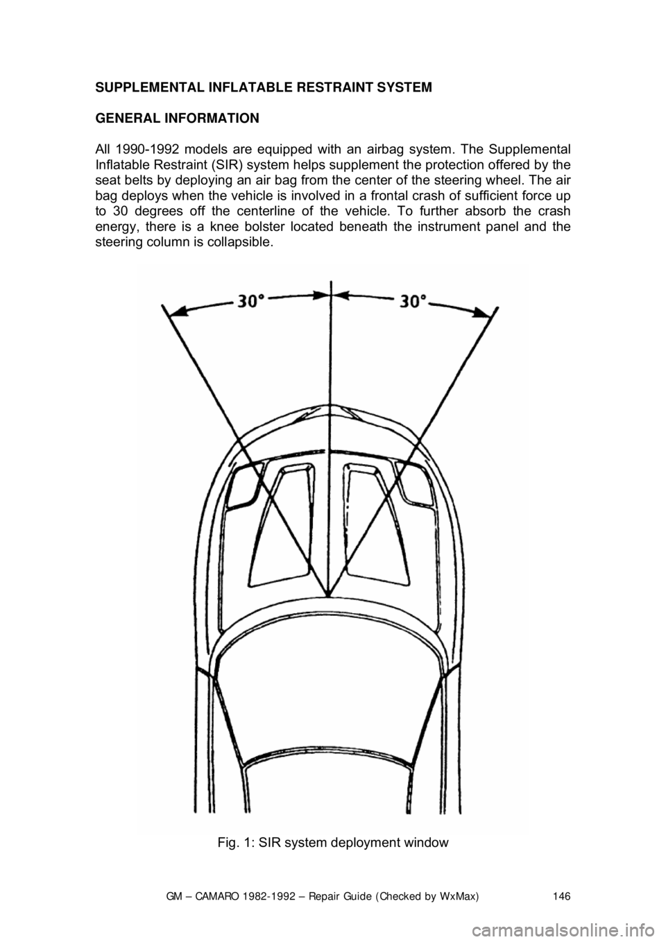
bag deploys when the vehicle is involved in a frontal crash of sufficient force up
to 30 degrees off the center line of the vehicle. To further absorb the crash
energy, there is a knee bolster located beneath the instrument panel and the
steering column is collapsible.
Fig. 1: SIR system deployment window
Page 148 of 875

GM – CAMARO 1982-1992 – Repair Guide (Checked by WxMax) 148
ARMING SENSOR
The arming sensor is a protective switch
located in the power feed side of the
deployment loop. It is calibrated to clos e at low level velocity changes (lower
than the discriminating sens ors). This assures that the inflator module is
connected directly to the 36 volt output of the DERM or battery voltage feed
when either of the discrim inating sensors close.
DISCRIMINATING SENSORS
The discriminating sensors are wired in parallel on the ground side of the
deployment loop. These sensors are calib rated to close with velocity changes
which are severe enough to warrant deployment.
SIR COIL ASSEMBLY
The SIR coil assembly consists of two cu rrent carrying coils. They are attached
to the steering column and allow rotation of the steering wheel while maintaining
continuous contact of the deployment loop to the inflator module.
INFLATOR MODULES
Each inflator module consists of an inflat able bag and an inflator (a canister of
gas generating material with an initiati ng device). When the vehicle is in a
frontal crash of sufficient force, current flows through the deployment loops.
Current flowing through the initiator ignite s the material in the inflator module.
The gas produced from this reaction rapidly inflates the air bag.
Fig. 2: Forward discriminating se nsor location on 1990-1992 models
Page 149 of 875

GM – CAMARO 1982-1992 – Repair Guide (Checked by WxMax) 149
Fig. 3: Passenger com partment SIR component lo cations on 1990-1992 models
SERVICE PRECAUTIONS
The DERM can maintain sufficient volt age to cause a deployment for up to 10
minutes after the ignition switch is tur ned OFF or the battery is disconnected.
Always disable the system when perfo rming service procedures ON OR NEAR
the system and it's components.
CAUTION - The disarming and arming procedures must be followed in the
order listed to temporarily disable the SI R system. Failure to do so could result
in possible air bag deployment, pers onal injury or otherwise unneeded SIR
system repairs.
DISARMING THE SYSTEM
1. Turn the steering wheel so that t he vehicle's wheels are pointing straight
ahead.
2. Turn the ignition switch to the LOCK position.
3. Remove the SIR or AIR BAG fuse from the fuse panel.
4. Remove the left side trim panel, t hen remove the Connector Position
Assurance (CPA) device and disconnec t the yellow two-way SIR harness
connector at the base of the steering column.
5. On vehicles with passenger side air bags, remove the glove box door
then disconnect the yellow two-way c onnector located near the yellow
24-way DERM harness connector.
With the fuse removed and the ignition sw itch ON, the air bag warning lamp will
be on. This is normal and does not indicate a SIR system malfunction.
Page 182 of 875

GM – CAMARO 1982-1992 – Repair Guide (Checked by WxMax) 182
ANTENNA
REMOVAL & INSTALLATION
Placement of tape on the right inner door edge will help prevent scratches
during the antenna removal an
d installation procedure.
1. Disconnect the negative battery terminal.
2. Remove the right side lower in strument panel sound insulator and
disconnect the antenna connection from the radio.
3. Raise and safely support the vehicle.
4. Disconnect the instrument panel harness from the radio.
5. Disconnect the power antenna lead, if equipped.
6. Disconnect the power antenna wire from the relay, if equipped.
7. Remove the right fender wheelhouse.
8. Loosen the fender-to-body attaching bolts and block the fender out.
9. Remove the antenna bezel and nut.
10. Remove the antenna assembly mounting screws.
11. Remove the grommet from the bul khead and pull the harness from the
vehicle interior.
12. Remove the antenna assembly from the vehicle.
In some cases, if the vehicle is equipped with a power antenna, it may be
repaired. Seek a profe ssional radio shop for pr oper repair of the antenna
assembly.
To install: 13. Install the antenna assembly into the vehicle.
14. Install the grommet and the harne ss into the vehicle interior.
15. Install the antenna assembly mounting screws.
16. Install the antenna bezel and nut.
17. Remove the fender block, tighten the fender-to-body attaching bolts.
Ensure any shims for the fender are reinstalled.
18. Install the right fender wheelhouse.
19. Lower the vehicle.
20. Connect the power antenna wire to the relay, if equipped.
21. Connect the power ant enna lead, if equipped.
22. Connect the instrument panel harness to the radio.
23. Connect the antenna connection to the r adio. Install the right side lower
instrument panel sound insulator
24. Connect the negative battery cable.
Page 200 of 875

GM – CAMARO 1982-1992 – Repair Guide (Checked by WxMax) 200
9. Lubricate the speedometer cable
with an appropriate lubricant, being
sure to cover the lower thirds of the cable.
10. Insert the cable into the casi ng, then connect the cable and casing
assembly to the speedometer.
11. Install the instrument cluster, then install the cluster attaching screws.
12. Install the instrument cluster trim plate.
13. On models without cruise control, connect the speedometer cable strap
at the power brake booste r. On models with cruise control, connect the
speedometer cable at the cr uise control transducer.
14. Connect the negative battery cable at the battery.
WIPER SWITCH
REMOVAL & INSTALLATION
The wiper switch is part of the multi-function lever, located on the steering
wheel column.
1. Disconnect the electrical connector of the multi-function lever, located
under the instrument panel.
2. Remove the protective cover from the wire.
3. Grasp the lever firmly, twist and pull (the tang on the lever must align
with the socket) the lever straight out.
4. Pull the wire through the steering column.
To install: 5. Slide a music wire tool through the steering column and connect the
lever wire to the tool wire; pull t he wire through the steering column.
6. Push the control lever into the sp ring loaded socket (be sure to align the
tang).
7. Install the protective cover to the wire.
8. Connect the electrical connector of the multi-function lever.
HEADLIGHT SWITCH
REMOVAL & INSTALLATION 1. Disconnect the negative batte ry cable at the battery.
2. Remove the four screws from insi de the defroster duct (instrument panel
pad securing screws).
3. Remove the screws which are under the lip of the instrument panel pad.
4. Remove the instrument panel pad.
5. On models equipped with air condition ing, remove the instrument panel
cluster bezel and the cluster.
6. Remove the radio speaker bracket.
7. Pull the headlamp switch knob to the ON position, depress the locking
button for the knob and shaft (locat ed on the switch), and remove the
knob and shaft.
8. Remove the switch bezel (retainer).
Page 219 of 875

GM – CAMARO 1982-1992 – Repair Guide (Checked by WxMax) 219
FUSE BLOCK
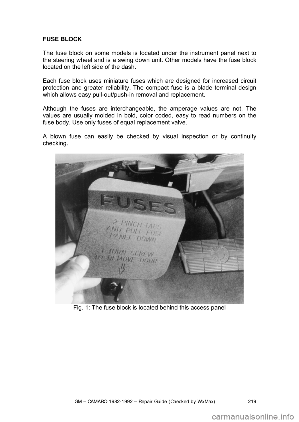
The fuse block on some models is loca
ted under the instrument panel next to
the steering wheel an d is a swing down unit. Other models have the fuse block
located on the left side of the dash.
Each fuse block uses miniature fuse s which are designed for increased circuit
protection and greater reliabi lity. The compact fuse is a blade terminal design
which allows easy pull-out/push- in removal and replacement.
Although the fuses are interchangeable , the amperage values are not. The
values are usually molded in bold, color coded, easy to read numbers on the
fuse body. Use only fuses of equal replacement valve.
A blown fuse can easily be checked by visual inspection or by continuity
checking.
Fig. 1: The fuse block is located behind this access panel