Page 17 of 102

Downloaded from www.Manualslib.com manuals search engine f l
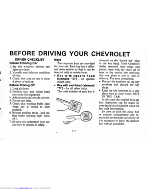
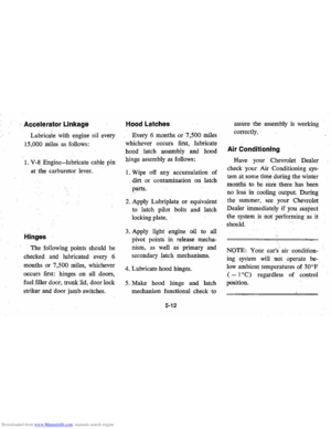
Starting the Engine
Automatic TransmISSion
Models
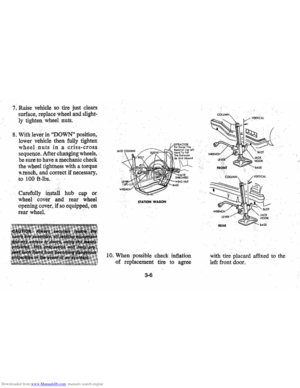
1. Apply the parking brake.
2. Place transmission selector
in uP" or f~Nn (UP" pre
ferred).
A .starter safety switch prevents
starter
operati on while the trans"
mission selector is in any drive
position.
(Iii! is necessary to
re-start the engine with the car .
moving , place the selector lever
in uN".)
3. Depress accelerator pedal and
acti vate starter
as outlined be
low for di1Ierent conditions .
IMPORTANT: ·00 not keep
the starter engaged for more
than
15 seconds at a time. Wait
1 0 or 15 seconds before trying
again.
• Cold Engine ~ Fully depress
. accelerator pedal and slowly
release .
With foot aU the
pedal,
crank the engine by
turning the ignition
key to the
Start
position -release when
engine starts.
If engine starts, bu t fails to
run,
repeat this procedure.
When engine is running
smoothly (approximately 30
seconds), the idle speed may
be reduced by slightly de
pressing the accel erator pedal
and then slowly releasing.
• Warm Engine-Depress ac
celerator pedal about halfway
and hold while cranking the
engine.
2-3
• Extremely Cold Weather
(Below
0 ° F.) (-18° C.) Or
After Car Has Been Stand
ing Idle Several Days
FuUy depress and release ac
celerator pedal two or three
times before cranking ' the
en
gine. With foot aU the .·accel
erator pedal, crank the engine
by turning the key to the
Start
position and relea se when en
gine starts.
Engine Flooded
Depress accelerator pedal and
hold
to floor while starting until en
gine is cleared of excess fuel and is
running smoothly . Never "pump"
the accelerator peda\. .
Warm-Up
Always let the engine idle for 20
to 30 seconds after starting and
drive at moderate speeds for
sev
eral miles, especially during cold
weather .
Page 18 of 102

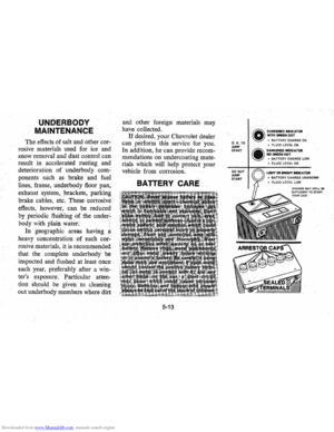
Downloaded from www.Manualslib.com manuals search engine Driving with the Chevrolet Automatic Transmissions
Your Chevrolet is equipped with a
Turbo Hydra-Matic automatic
transmission. After starting the
en
gine with.the selector lever in N
(Neutral) or P (Park) position,
select the range desired (see table)
and
dt)press the a.ccelerator. A
gradual start with a steady increase
in accelerator pressure will result in
best possible fuel economy. Rapid
acceleration for fast starts
will re
sult in greater fuel consumption.
Automatic transmission shift
quadrants of all
OM cars continue
the uniform sequence of selector
positions. This particularly benefits multicar
families and those
Who oc
casionally drive. other cars. Shift in
dicators are arranged with "Park"
position at one end, followed in se
quence by "Reverse""" "Neutral"
and the forward driving ranges.
All automatic
tnlOsmiSsions are
equipped
witha. starter safety
switch designed to. permit starting
the engine only when the.
transmis
sion selector is in the "Park" or
"Neutral" position. For additional
engine braking
effect, as sometimes
needed
in mountainous driving,
place the transmission in a
inter
mediate range.
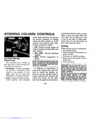
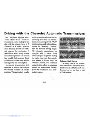
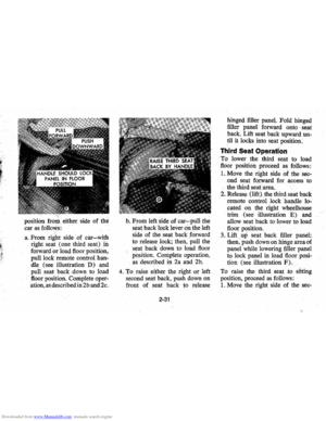
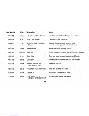
Column Shift Lever
The heavy line in the illustra
tions indicates the niovement of the
shift lever as
it is lifted to shift into
Reverse, L
2, L., and
into or out
of Park position.
Page 19 of 102

Downloaded from www.Manualslib.com manuals search engine Turn Signals and Lane
Change Feature
The tum signal lever is located on
·the l eft side of the steering column
immediately under the steering
wheel. The lever is moved upward
to signal a right tum and down·
ward to signal a left tum. Lamps
on the front and rear of the car
transmit this signal to other motor
ists and pedestrians. The ignition
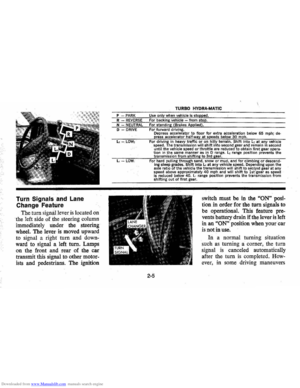
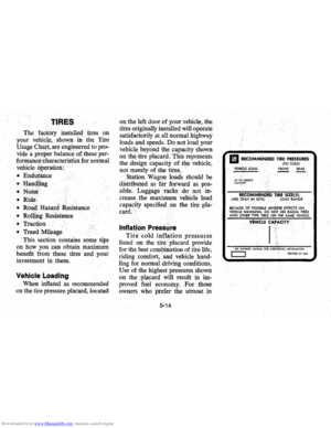
P PARK R REVERSE N - NEUTRAL
D DRIVE
TURBO HYDRA·MATIC
Use only when vehicle is stopped . For backing vehicle from stop. For standing (Brakes Applied), For forward driving.
Depress accelerator to floor for extra acceleration below 65 mph; depress accelerator half-way at speeds below 30 mph. For driving in hea.vy traffic or on hilly terrain. Shift Into l2 at any veh icle
speed. The transmiss ion will shift into second gear and remain in sec ond until the vehicle speed or throttle are reduced to obtain first gear operation in the same -manner 85 in 0 r a n ge. ~ range posit ion prevents the
transmiss ion from shifti ns to 3rd gear.
For hard pulling through sand, snow or mud, and for climbing or descending steep /lrades. Shift in~o LI at any vehicle speed. Depending upon the axle ratio of the v. ehicte the transmission will shift to sec~nd gear at any
speed above approximately 40 mph and will shift to 1st \gear 2IS speed is reduced below 40. II range position pr~vents the transm iss ion from shifting out of first. gear.
2-5
switch must be in the "ON" posi
tion in order for the turn signals to
be operational. This feature pre
vents battery drain if the lever is left
in an
"ON" position when your car
is not in use.
In a normal turning situation
such
as turning a comer , the turn
signal
is canceled automatically
after the
tum is completed. How
ever, in some driving maneuvers
Page 20 of 102

Downloaded from www.Manualslib.com manuals search engine such as changing lanes on an ex
pressway , the steering wheel
is not
turned back sufficiently after com
pleting the turn to automatically
cancel the turn signal.
For con
venience
,in such maneuvers, the
driver can flash the turn signals by
moving the turn signal lever part
way (to tlie first stop) and holding
it there. The lever returns to the
neutral
or canceled position when
the driver releases his hold on the
lever. A
green light on the instrument
cluster flashes to indicate proper
operation of the front and rear turn
signal lamps.
If the indicator lamp
. remains on and does not flash,
check for a defective lamp bulb.
If
the indicator fails to light when
the lever
is moved , check the fuse
and indicator bulb.
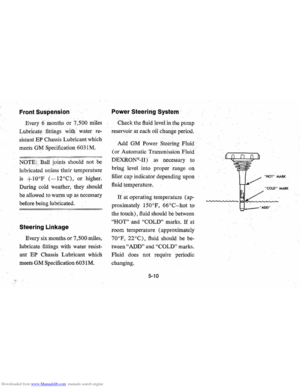
Power Steering
If the steering system power as
sist fails due to some malfunction, or
because the. engine has stalled,
the car can still be steered. How
ever; much greater effort is re
quired particularly in sharp turns.
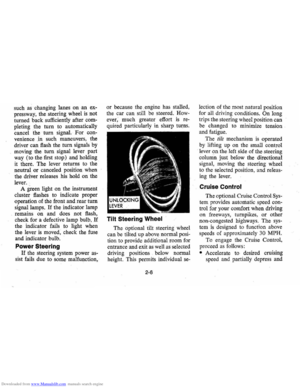
Tilt Steering Wheel
The optional tilt steering wheel
can be tilted up above normal posi
tion to provide additional room for
entrance and exit
as well as selected
driving positions below normal
height. This permits individual
se-
2-6
lection of the most natural position
for all driving conditions.
On long
trips the steering wheel position can
be changed to minimize tension
and fatigue.
The
till mechanism is operated
by lifting up on the small control
lever
on the left side of the steering
column just below the directional
s ignal , moving the steering wheel
to the selected position, and releas
ing the lever.
Cruise Control
The optional Cruise Control Sys
tem provides automatic speed con
trol for your comfort when driving
on freew a
ys, turnpikes, or other
non-congested highways. The
sys
tem is designed to function above
speeds of approximately
30 MPH.
To enga ge the Cr:uise Control,
proceed
as follows:
• Accelerate to desired cruising
speed and partially depress and
Page 21 of 102

Downloaded from www.Manualslib.com manuals search engine release the controlputton at the
e,ndof the turn signallever.
'. ~
• Remove your fool from the ac
celerator pedal and desired speed
will automatically
be maintained . /.
• To change autoIllfltic speed set
ting , press
con.tllol button until
it bottom s and
hold until desired
speed is attain!id.
•
Before releasi~g control button,
hesitate at
th!'!igartially depresse\l
position, th~I},:,remove your foot
from the
ac~,~lerator. If control
button
is IIW t fully depressed,
whenchangi#g speed setting, the
car
will resume your previously
selected
spe~d.
To disengage system, lightly de
press brake
p~al.
, ,.,
Horn
The .horn on your Chevrolet
is actuated by firmly pressing on
the pad in the center of the steering
wheel.
' As a good motorist, use of the
horn should
be kept at a minimum .
However , acquaint yourself
as soon
as possible with this function of
your car, should it ever become
necessary to give a warning to a
pedestrian or another , motorist.
NOTE: For operation of hazard
flasher, see page .3-1, iii section 3,
"In Case of Emergency."
Page 22 of 102

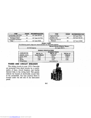
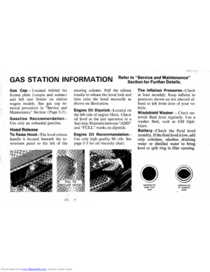
Downloaded from www.Manualslib.com manuals search engine FLOOR· CONTROLS
Braking System
The service brake system is de
signed for braking performance
under a wide range of driving con
ditionseven when the vehicle is
loadedto:its full rated vehicle load.
When replacement parts are
re
quired, OM and Delco parts are
recommended.
Power Brakes
• On your Chevrolet if power
assjst to the brakes
is interrupted
due to a staJled engine or some
malfunction,
two or more brake
applications normaJly can
be
made using reserve power.
• lithe brake pedal is held down,
the system
is designed to bring
the car
to a full stop on reserve
power. However, the reserve
power
is partially depleted each time
the
brake pedal is . applied
apd released. ' Do not pump
brakes
when brake power assist
has been interrupted except
when necessary in order
to main'
tain steering control on slippery
slirlaces.
•
When reserve power is ex
hausted, the vehicle can still be
stopped by applying greater force
to the pedal.
2-8
NOTE: Operation of the brake
system warning light
is covered on
page 2-12 in the section on "In-
strument Panel", .
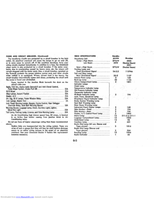
Parking Brake
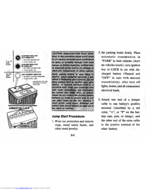
• To set parking brake, fully de
pre~s foot ped,al at far left side.
• For maximu!'l holding power,
depress regular brake pedal with
the right foot at the same time.
• To release parking brake,' pull
"BRAKE RELEASE" lever. on
lower left
instr\iment panei. .". -
• As a reminder, the brake system
warning light
is desjgned to
glow whenever the parking
brake control
is not fully re
leased, and the ignition is on.
• Never drive car with parking
brake set
as this may overheat
or otherwise damage rear brakes.
Page 23 of 102

Downloaded from www.Manualslib.com manuals search engine NOTE: "Riding the brake" by rest
ing your foot on the brake pedal
when not intending to brake can
cause abnormally
high brake tem
peratures, excessive lining wear and
possible damage to the brakes,
in
addition to wasting.gasoline.
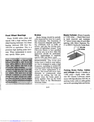
Self-AdjustingiBrakes
• Brakes on th(i; ' car (except for ••.
the parking }prake) are self
adjusting, designed to eliminate
periodic
brake adjustments.
• Drum brake adjustment is made
automatically
as the brakes are
applied while car is moving
backwards.
• Disc brake . adjustment is made
automatical1y with each brake
application.
• If excess brakep~dal travel de
velops, drive alternately back-
ward and forward (several
times) and apply brakes firmly
in each direction.
• See )lour dealer if normal pedal
travel is not restored, or if there
is a rapid increase in pedal travel,
which could be a sign of other
brake trouble.
See y6ur dealer also if
adjust
ment of the parking brake is
required;
REMINDER: The front disc
brakes have a built-in wear indica
tor that is designed to make a high
frequency squealing,
or cricket-like
warning sound when the linings are
worn to where replacement
is re
quired. The sound will occur inter
mittently or continuously when
wheels are rolling, but will
dis
appear when the brake pedal is ap-
2-9
plied firmly. See also the various
brake checks listed in the
Chevro
let maintenance schedule folder.
Headlight Beam Switch
"High" and "low" headlight
beams are controlled by the floor
button at your left foot. The
indi
cator, located next to the speed
ometer dial, will light up when the
high beams are in use.
Page 24 of 102
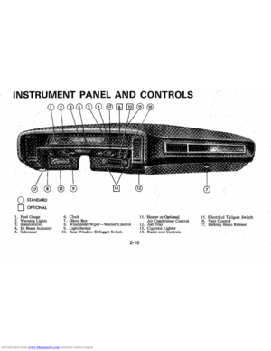
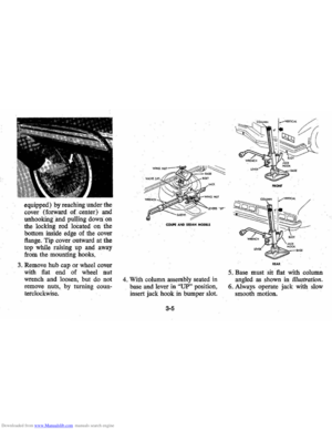
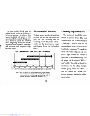
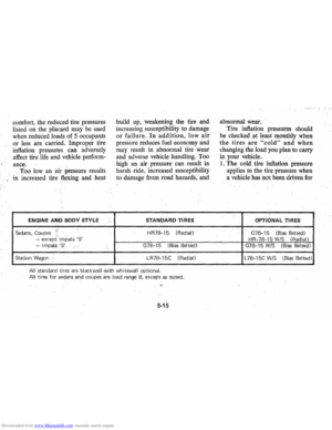
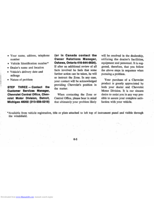
Downloaded from www.Manualslib.com manuals search engine INSTRUMENT PANEL AND CONTROLS
o STANDARD
o OPTIONAL
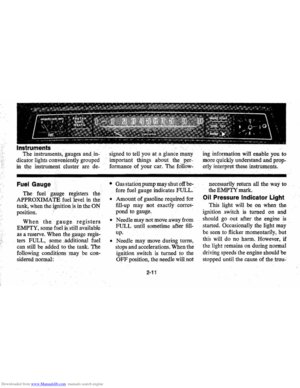
1. Fuel Gauge 2. Warning Lighls 3. Speedometer 4. Hi Beam Indicator 5. Odometer
6. Clock 7. Glove Box 8. Windshield Wiper-Washer COntrol 9. Light Switch to. Rear Window Defogger Switch
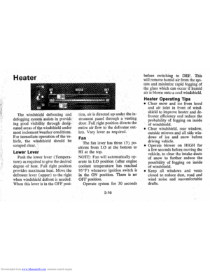
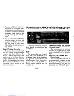
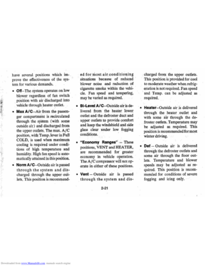
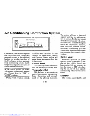
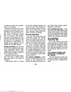
11. Heater or Optional
Air Conditioner Control
12. Ash Tray 13. Cigarette Lighter 14. Radio and Controls 1
5 . Electrical Tailgate Switch
16. Vent Control 17. Paridng Brake Release
2-10