Page 25 of 102

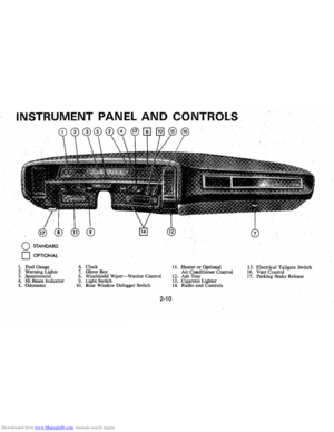
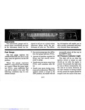
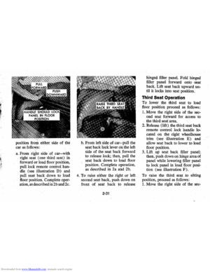
Downloaded from www.Manualslib.com manuals search engine The instruments, gauges and. in
dicator lights conveniently grouped
in the instrument cluster are de-
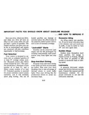
Fuel Gauge
The fuel g!fllge registers the
APPROXIMATE fuellevel in the
tank , when the ignition
is in the ON
po sition .
When the gauge registers
EMPTY, some fuel is.s till available
as a reserve. When the gauge
regis
ters FULL, sOme .. additional fuel
can still be added to the tank. The
following conditions may
be con
sidered normal: signed
to tell you at a glan ce many
important things about ihe
per
formanceof your car. The follow- .
•
G as station pump may shut off be
fore fuel gauge indicates FULL.
o Amount of gasoline required for
fill-up may not exactly
corres
pond to gauge.
o Needle may not move away from
FULL until sometime after fill
up.
o Needle may move during turns,
stops and accelerations. When the
ignition switch is turned to the
OFF position , the needle will not
2-11
ing information will enable you to
mor e quickly understand and
prop
erly interpret these instrume!lts.
necessarily return all the way
to
the EMPTY mark.
Oil Pressure Indicator Light
This light will be on when the
ignition switch
is turned on and
s hould go out after the engine
is
started . Occasionally the light may
be seen to flicker momentarily , but
this will do no harm. However,
if
the light remains on during normal
drivin g speeds the engine should
be
stopped until the cause of the trou-
Page 26 of 102

Downloaded from www.Manualslib.com manuals search engine ble'can be located and corrected .
. Driying the car with low oil pillS'
sure can:cause · serious ' engine
damage.
Genera~orlndicator Light
The red light will go on when
the
ignition key is in the "on " posi,
tion, b~f before the engine is
started.'J\fter the engine starts, the
light .
sho'uld go out and remain out.
If the Hght remains on when engine
is runlling, have your Authorized
Chevrolet Dealer locate and cor,
reCI the trouble as soon as possible,
Engine Temperature
Indicator Light
, This indicator light is provided
in the instrument cluster to quickly
warn
of an overheated engine. With
the ignition switch in the
5T AR T
position, the red TEMP indicator
will light to let you know that it is
operating properly. When
the engine
is started , the
red light will go out immediately,
It will light up at no other time
unless for some reason the engine
.
reaches a dangerously high oper,
atingtemperature. If the light
comes on during
extreme driving
conditions, such
as an extended
idle, turn
off the air conditioner (if
used }.and run the engine slightly
faster than
idle. speed with the
transmission in neutral gear .
If the
light does not go
off within a short
period of time
(F2 minutes), then
tum the engine off until the cause
of the.
overheating is corrected;
Glance at the
Ins.trument cluster
frequently as you drive to see if
this light
is on. '
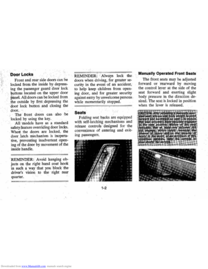
Brake System Warning
Light
.
The service .. brake system is a
dual system designed
so that. one
part will provide some braking
2-12
action in the event of loss of hy'
draulic pressure in the other part of
the system.
If the ,warning light
labeled
"BRAKE," located in the
speedometer face, comes on .and
stays on when the ignition
is on and
'after · the brakes have been firmly
applied, it may indicate that
there
is a malfunction in one part of the
brake system.
'
•
As ~ reminde;, the light is de,
signed:to
come on with the park,
ing brake applied and the ignition
on.
• The light is also designed to
come on, during ;engine starting
to verify that the bulb is operating
. properly.
• Have system repaired '. if light
does not come
on' during check.
• This warning light, is not a sub
stitute for the visual check of
brake fluid level required
as part
of normal maintenance.
Page 27 of 102

Downloaded from www.Manualslib.com manuals search engine If the light comes oQ:
• The :parking brake control is not
fully
relea sed or, ,,:
• The service brake system is
partially inoperative .
What to do :
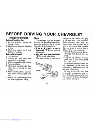
1. Check that the parking brake
is released. If it is ...
2.
Pull off the road and stop, care
fully-remembering that:
'
•
Stoppin g "distances may be
greater. ' '0:
• Greater pMal effort may be
required .: ;
• Pedal
travel may be greater.
3. Try out b~ake operati on by start
ing and
stopping on road shoul
der-then :
• If you judge such operation to
be safe , proceed cautiously at
a safe speed to neare st dealer
for repair.
• Or have car towed to dealer
}or repair .
Continued operation ' of the car in '
this condition
is dangerous.
Headlight High Beam
Indicator Light
The headlights of your ' car have '
high and
low, beams to provi(je you
with proper night-time visibility
for most . driving
conditioQs. The
"low" beams are used during most
city driving. The
"high" beams are
especially useful when
drh;ing on
dark roads since
they provide ex
cellent long range illumination.
The headlight beam
indicator will
be on whenever the high beams or
"brights" are in use. The Headlight
Beam
Switch controls the headlight
beams (see
Page 2-9).
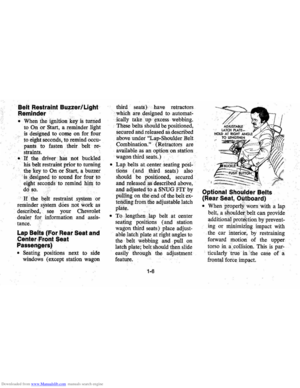
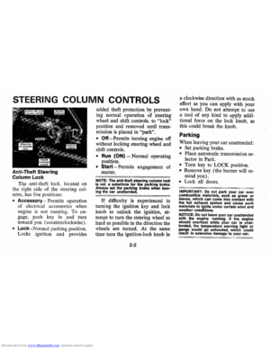
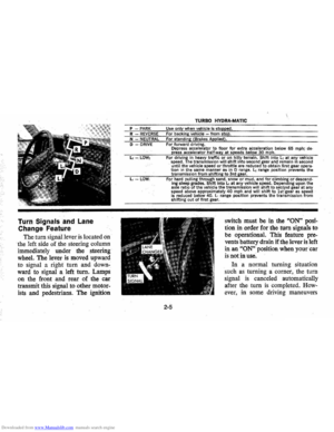
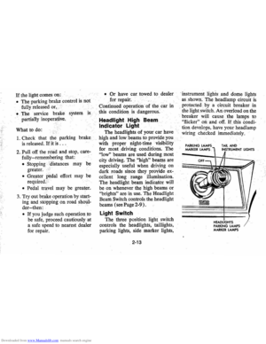
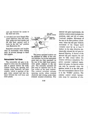
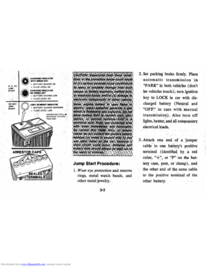
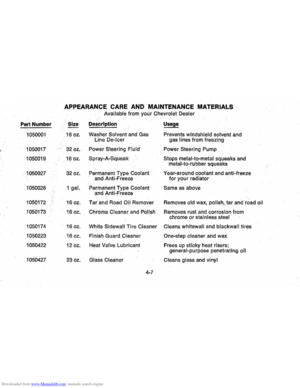
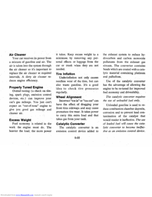
Light Switch
The three position light switch
controls the headlights " taillights,
parking lights, side marker lights,
2-13
'i nstrument lighis and dome lights
a s ,shown . The headlamp circuit
is
protected·· by a circuit breaker in
, tne lightswit ch . An overload on the
breaker will cause the lamps to
"flicker" 00 and off. If this condi
ti on develop s, hav e your headlamp
wiring check ed immedi ately.
PARKING MARKER LAMPS TAIL AND
PARKING LAMPS MARKER LAMPS
LIGHTS
Page 28 of 102

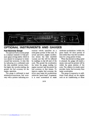
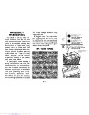
Downloaded from www.Manualslib.com manuals search engine NAL INSTRUMENTS AND 'GAUGES
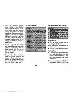
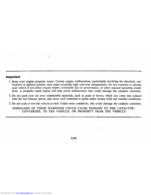
j:;".,nn,mv Gauge
The.optional fuel economy gauge
is a co~stant reminder to help pro
mote ' g~od driving . habits which in
turn should be recognized in better
overalfJuel economy, It does this
by
indicatingon a calibrated scale
the inlet manifold vacuum
level
the higher the vacuum reading, the
greater the fuel economy for the
engine
operation,
The gauge is calibrated to read
minimum -to-maximum fuel
econ
omy with a pointer iudicating eeo-
nomical· vehicle operation on a
solid green portion of the
scale, In
actual operation, )mgiue accelera
tionlowers the " inlet manifold
vacuum and this
will be reflected
by
r~~qings on tbe 'left part of the
scale, The greater" the acceleration
the lower . the gauge
readil1g (or
engine vacuum) and the poorer the
fuel
eeonomyat that instant. To
improve engine fueleconol)lY the
driver must make his accelerations
within
the "green band". In general ,
it
is most economical to make
2-14
moderate accelen'ltions (within the
green band) for short periods of
time rather
thanv«ry slow accelera
tions for along period of time.
When
the desired traveling speed
is attained, the gauge will. reach a
steady state
'.l1-nd the ,pointer will be
within the green portion of the
scale. The vehicle at
'a steady speed
providesbetterfuel.economy than
under acceleration. '
The gauge
is, responsive to addi
tional loads placed on the engine
such
as air conditioning or those
Page 29 of 102

Downloaded from www.Manualslib.com manuals search engine I0'ads imp0'sed by .. trlliler hauling.
Cempensatef0'r thes~ l0'wer gauge
readings
resulting frem these heaVy
'Ib ads t0' produce gO'?d fuel ec0'n
emy.
. <,
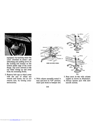
Engine Temper~'iure. Gauge
This 0'Pti0'n~r',,'gauge indicates
c0'0'lant temperaplre which will
yary with air
teqiperature and 0'P
erating c0'nditi{>,iiS. The ignitien
switch must
be;" 0'n f0'r accurate
,re
idling in very hqtweather will caus~
the P0'inter to'iim0'vebey0'nd tije
center 0'f the ljimd. Should P0'inter
m0've t0' the line at the "H" end of
the band , stop engine 0'r reduce ,
speed
t0' penllit engine t0' cool.
Headlamp "ON"
Warning Buzzer
The eptienal headlamp reminder
buzzer provides
an audible warn
ing that the main light switch is in
one 0'f the "0'n"P0'siti0'ns ; either
pMking lights Of headlights.
The reminder ,buzzer is actuated
0'nly whenthe igniti0'n switch is
turned
i0' '''OFF'' er "LOCK" posi
ti0'n,
Clock
Reset th~ cl0'ck,if yeur car is S0'
'equipped, by pulling eut the kn0'b
.
and turning the hands cl0'ck\\fise if
slew , c0'unterclockwise if fast. This
will, if the
cl0'ck errer is five min
utes er. m0're,~utematicallyc0'm
pen sate f0'r tim.e' gain 0'r l~g, Sev
eral resettings, sev.eral daysi',apart,
maybe needed te pr0'perl y adjust
the
clOCk mechanism . Have yeur
c
l0'ck cleaned and 'eiled by a cem"
petent .cl0'ck serviceman "at least
every
twe years,
Cigarette Lighter
The cigarette lighter. is I0'cated
en the instrument panel face, T0'
,2-15
operate, push it in, When it be
C0'm.es heated, it aut0'matically P0'PS
eut ready fo r use,
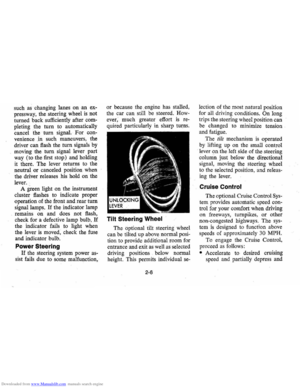
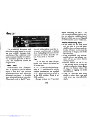
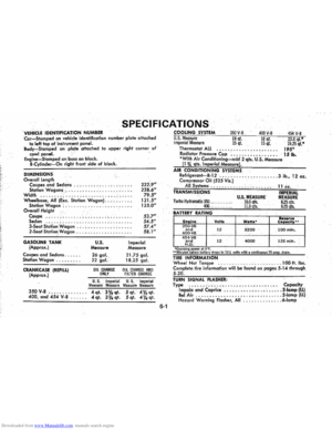
WindshiEild Wiper and
Washer
The windshield wiping system
op(;lratesat tW0' speed s and is de
.
signed t0'wipe clear specific areas
of the windshield under m0'st in
, Clement "''leath
er cenditiens, The
windshielrlwipers w0'rk electri
cally and are not affected ' by en
gineeperatien,
FIlsh . the centrel levetDewn te
start the electric windshie ld wiper,
The
tW0'-speed electric wiper has
botli a' "lew " and a "high" speed
pesitien,
Pressing the centrel will send a
measured
ameunt ef water 0'r ether
cleaning agent ent0' the windshield,
Fill the washer
jar only % full
during the winter
te allew fer eX
pansien if the temperature sh0'uld
Page 30 of 102
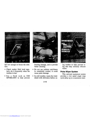
Downloaded from www.Manualslib.com manuals search engine fall low enough to freeze the solu
tion.
• Check washer fluid level regu
larly-do it frequently when the
weather
is bad.
• Use a fluid such as GM
OPTIKLEEN · to help prevent freezing
damage, and
to provide
better cleaning.
• Do not use radiator anti-freeze
in windshield washer; it could
cause paint damage.
• In cold weather, warm the wind
shield with defrosters before us-
2-16
ing washer-to help prevent ic
ing that may seriously obscure
vision.
Pulse Wiper System
This optional equipment system
provides a low speed single wipe
cycle delay up
to a maximum inter-
Page 31 of 102

Downloaded from www.Manualslib.com manuals search engine -';
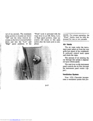
val of ten seconds. The maximum
delay . position
is located just below
"Off" and the delay interval de
creases as the lever is moved further
down and into
. the "Low" and
"High" speed pas'itions. If the
"Wash" cycle is activated with the
wiper lever
in an Off, Delay, Low,
or High speed position , wiper op~
eration will return to this same
action after the wash cycle is com
pleted.
2-17
NOTE: For proper operation, the
"Wash" ,button must be fully de
pressed for one or two seconds.
Air Vents
The air vents under .the . instru~
ment panel admit air from the vent
grille just ahead . of the windshield.
A push-pull
control knob opens
and closes the vents.
,
The amount of air entering the
c .ar through this system
is depend
ent upon vehicle speed,
The vent lever on the instrument
. panel controls the air flow ihrough
the instrument panel outlets (up
per).
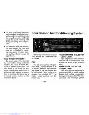
Ventilation System
Your 197 6 Chevrolet incorpo
rates a ventilation system that pro-
Page 32 of 102
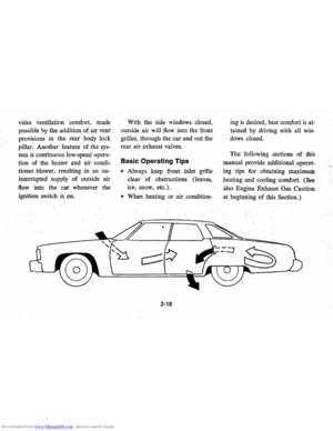
Downloaded from www.Manualslib.com manuals search engine vides ventilation . coillfort , made
possible
by the additionaf air veilt
provisions ' in the rear 1:>ody lock
pillar. Another feature of the
sys
tem is continuous low:speed opera
tion of the heater and air condi
tioner blower , resulting in an un
interrupted
supply of outside air
flOw into the car whenever the
ignition switch is.on. With
the side windows closed,
out side air will
flow into the front
grilles, through the car and out the
rear air exhaust valves.
Basic Operating Tips
'. Always keep front Jnlet grille
clear of obstructions (leaves,
ice, snow, etc.).
• When heating or air condition-
2-18
ingis desired , best comfort is at
tained by driving with all win
dows closed.
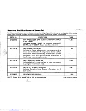
The following sections of this
manual provide additional operat-
. ing tips for obtaining maximum
heating and
cooling comfort. (See
also Engine Exnaust Gas Caution
at beginning of
this Seotion.)