1976 CHEVROLET MONTE CARLO parking brake
[x] Cancel search: parking brakePage 3 of 102

Downloaded from www.Manualslib.com manuals search engine ,
BEFORE DRIVING YOUR CHEVROLET
DRIVER CHECKLIST
Before Entering Car
1. See that windows ; mirrors and
lights are clean.
2. Visually note inJIation condition
of tires.
3. Check that area to rear is clear
if about to back up.
Before Driving Off
1. Lock all doors.
2. Position seat, jmd adjust head
restraints, if
so ¢quipped.
3. Adjus!insidean'd outside mirrors.
4. Fasten seat belts.
5. Check that warning bulbs light
when key
is turned to start
position. .
6. Release parking brake ( and see
that brake warning light turns
off). ,
7. Be sure you understand your car
and how
to 'operate it safely.
Keys
Two separate keys are provided
for your car. Each key has a
differ
ent cross section so that it can be
inserted only in certain locks.
• Key with s qua r e hell d
(stamped "e") -for ignition
switch only.
• Key with oval head (stamped
"O")-for all other locks.
,
The code number of each key is
All OTHeR LOCKS
1-1
stamped on the "knock out" plug
in the '
key-bead. Your Chevrolet
dealer removed these plugs
and,.
placed them with the spare set of
keys in the special key envelope
. that was given to you at time of
delivery.
For your protection:
• Record the numbers on the key
envdope and discard the key
plugs.
• Keep the key envelope in a safe
place such
as YOII! wallet, NOT
IN THE CAR.
In the event
the original keys are
lost,
dl!plicates can be made by
your dealer or a locksmith using the
key code information.
Be sure to lock the Klove box
or console
90mpartment and re~
move the key from the car whenever
it is necessary to leave the ignition
key with
an attendant.
Page 16 of 102

Downloaded from www.Manualslib.com manuals search engine STEERING COLUMN CdNTROLS
Anti-. Steering
Column Lock
The
anti-th eft lock, located on
the right side of the stee ring col
umn, has five positions:
• Accessory -Permits operation
of electr i
cal accessories when
engine is not running. To
en
gage, push key in and turn
toward you (counterclockwise).
• Lock-Normal parking position.
L
ock s igniti on and provides added
theft protection
by prevent
ing normal operation of steering
wheel and shift controls . to
"lock"
po sition and removed until trans
mission is placed in "park".
• Off
-Permits turning engine off
without locking steering wheel and
shift controls.
• Run (ON) -Normal operating
position
. .
•
Start -Permits engagement of
starter.
NOTE: The ontl-theft otee,lng column lock is not 8:,lubltItUte tor· the parking brake. Always let the , parking brak, when leaving the car una"ended.
If difficulty is experienced in
turning the ignition key and lock
knob to unlock the ignition,
at
tempt to turn the steering wheel lIS
hard as possible in the direction the
wheels are turned.
At the same
time turn the ignition-lock knob in
2-2
a clockwise direction wi(h as.much
effort
as you can apply with your
own hand. Do not attempt to
use
a tool of any kind to apply addi
tional force on the lock knob, as
this could break the knob.
Parking
When leaving your car unattended:
• Set parking brake.
• Place automatic transmission se
lector in Park.
•
Turnkey to LOCK position.
• Remove key (the buzzer will re
mind you).
• Lock all doors.
IMPORTANT : Do not park your car over combustible materials, such 8S grlss or leaves, which can come Inlo contact with the hot exhaust system and cause such materials to Ignite under certain wind and weather condition ••
NOTICE:
Do not I.ave your car unattended with ~ engine running. If the engine
should overheat While your car is -unat·
tended , the temperature warning light or gauge would go unheed9d, which could result in extensive damage to your car.
Page 17 of 102

Downloaded from www.Manualslib.com manuals search engine f l
Starting the Engine
Automatic TransmISSion
Models
1. Apply the parking brake.
2. Place transmission selector
in uP" or f~Nn (UP" pre
ferred).
A .starter safety switch prevents
starter
operati on while the trans"
mission selector is in any drive
position.
(Iii! is necessary to
re-start the engine with the car .
moving , place the selector lever
in uN".)
3. Depress accelerator pedal and
acti vate starter
as outlined be
low for di1Ierent conditions .
IMPORTANT: ·00 not keep
the starter engaged for more
than
15 seconds at a time. Wait
1 0 or 15 seconds before trying
again.
• Cold Engine ~ Fully depress
. accelerator pedal and slowly
release .
With foot aU the
pedal,
crank the engine by
turning the ignition
key to the
Start
position -release when
engine starts.
If engine starts, bu t fails to
run,
repeat this procedure.
When engine is running
smoothly (approximately 30
seconds), the idle speed may
be reduced by slightly de
pressing the accel erator pedal
and then slowly releasing.
• Warm Engine-Depress ac
celerator pedal about halfway
and hold while cranking the
engine.
2-3
• Extremely Cold Weather
(Below
0 ° F.) (-18° C.) Or
After Car Has Been Stand
ing Idle Several Days
FuUy depress and release ac
celerator pedal two or three
times before cranking ' the
en
gine. With foot aU the .·accel
erator pedal, crank the engine
by turning the key to the
Start
position and relea se when en
gine starts.
Engine Flooded
Depress accelerator pedal and
hold
to floor while starting until en
gine is cleared of excess fuel and is
running smoothly . Never "pump"
the accelerator peda\. .
Warm-Up
Always let the engine idle for 20
to 30 seconds after starting and
drive at moderate speeds for
sev
eral miles, especially during cold
weather .
Page 22 of 102
Downloaded from www.Manualslib.com manuals search engine FLOOR· CONTROLS
Braking System
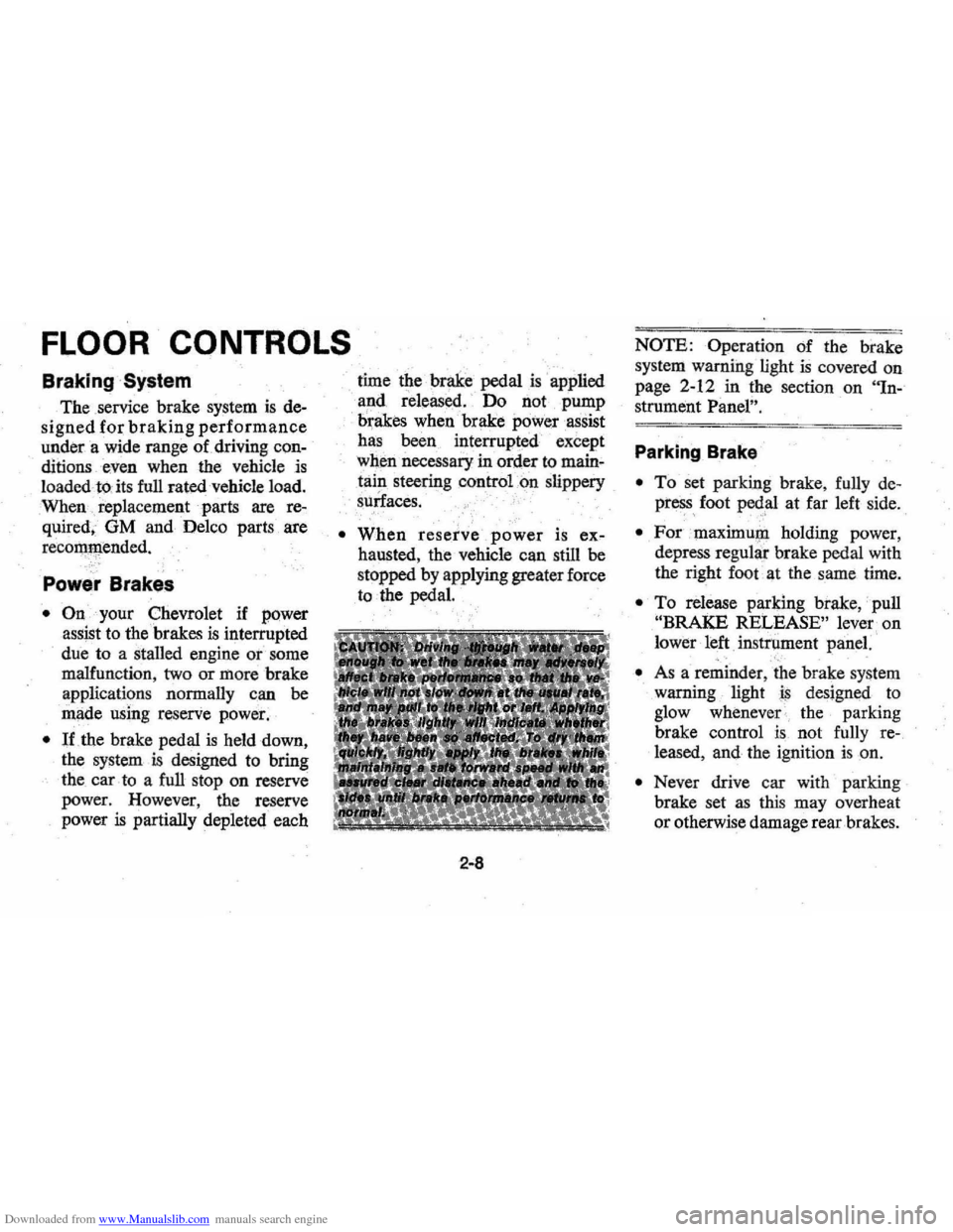
The service brake system is de
signed for braking performance
under a wide range of driving con
ditionseven when the vehicle is
loadedto:its full rated vehicle load.
When replacement parts are
re
quired, OM and Delco parts are
recommended.
Power Brakes
• On your Chevrolet if power
assjst to the brakes
is interrupted
due to a staJled engine or some
malfunction,
two or more brake
applications normaJly can
be
made using reserve power.
• lithe brake pedal is held down,
the system
is designed to bring
the car
to a full stop on reserve
power. However, the reserve
power
is partially depleted each time
the
brake pedal is . applied
apd released. ' Do not pump
brakes
when brake power assist
has been interrupted except
when necessary in order
to main'
tain steering control on slippery
slirlaces.
•
When reserve power is ex
hausted, the vehicle can still be
stopped by applying greater force
to the pedal.
2-8
NOTE: Operation of the brake
system warning light
is covered on
page 2-12 in the section on "In-
strument Panel", .
Parking Brake
• To set parking brake, fully de
pre~s foot ped,al at far left side.
• For maximu!'l holding power,
depress regular brake pedal with
the right foot at the same time.
• To release parking brake,' pull
"BRAKE RELEASE" lever. on
lower left
instr\iment panei. .". -
• As a reminder, the brake system
warning light
is desjgned to
glow whenever the parking
brake control
is not fully re
leased, and the ignition is on.
• Never drive car with parking
brake set
as this may overheat
or otherwise damage rear brakes.
Page 23 of 102
Downloaded from www.Manualslib.com manuals search engine NOTE: "Riding the brake" by rest
ing your foot on the brake pedal
when not intending to brake can
cause abnormally
high brake tem
peratures, excessive lining wear and
possible damage to the brakes,
in
addition to wasting.gasoline.
Self-AdjustingiBrakes
• Brakes on th(i; ' car (except for ••.
the parking }prake) are self
adjusting, designed to eliminate
periodic
brake adjustments.
• Drum brake adjustment is made
automatically
as the brakes are
applied while car is moving
backwards.
• Disc brake . adjustment is made
automatical1y with each brake
application.
• If excess brakep~dal travel de
velops, drive alternately back-
ward and forward (several
times) and apply brakes firmly
in each direction.
• See )lour dealer if normal pedal
travel is not restored, or if there
is a rapid increase in pedal travel,
which could be a sign of other
brake trouble.
See y6ur dealer also if
adjust
ment of the parking brake is
required;
REMINDER: The front disc
brakes have a built-in wear indica
tor that is designed to make a high
frequency squealing,
or cricket-like
warning sound when the linings are
worn to where replacement
is re
quired. The sound will occur inter
mittently or continuously when
wheels are rolling, but will
dis
appear when the brake pedal is ap-
2-9
plied firmly. See also the various
brake checks listed in the
Chevro
let maintenance schedule folder.
Headlight Beam Switch
"High" and "low" headlight
beams are controlled by the floor
button at your left foot. The
indi
cator, located next to the speed
ometer dial, will light up when the
high beams are in use.
Page 27 of 102
Downloaded from www.Manualslib.com manuals search engine If the light comes oQ:
• The :parking brake control is not
fully
relea sed or, ,,:
• The service brake system is
partially inoperative .
What to do :
1. Check that the parking brake
is released. If it is ...
2.
Pull off the road and stop, care
fully-remembering that:
'
•
Stoppin g "distances may be
greater. ' '0:
• Greater pMal effort may be
required .: ;
• Pedal
travel may be greater.
3. Try out b~ake operati on by start
ing and
stopping on road shoul
der-then :
• If you judge such operation to
be safe , proceed cautiously at
a safe speed to neare st dealer
for repair.
• Or have car towed to dealer
}or repair .
Continued operation ' of the car in '
this condition
is dangerous.
Headlight High Beam
Indicator Light
The headlights of your ' car have '
high and
low, beams to provi(je you
with proper night-time visibility
for most . driving
conditioQs. The
"low" beams are used during most
city driving. The
"high" beams are
especially useful when
drh;ing on
dark roads since
they provide ex
cellent long range illumination.
The headlight beam
indicator will
be on whenever the high beams or
"brights" are in use. The Headlight
Beam
Switch controls the headlight
beams (see
Page 2-9).
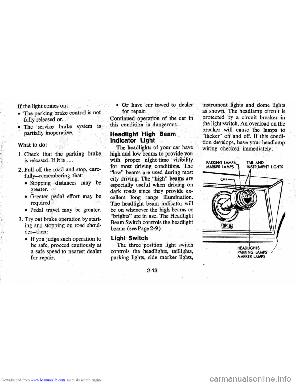
Light Switch
The three position light switch
controls the headlights " taillights,
parking lights, side marker lights,
2-13
'i nstrument lighis and dome lights
a s ,shown . The headlamp circuit
is
protected·· by a circuit breaker in
, tne lightswit ch . An overload on the
breaker will cause the lamps to
"flicker" 00 and off. If this condi
ti on develop s, hav e your headlamp
wiring check ed immedi ately.
PARKING MARKER LAMPS TAIL AND
PARKING LAMPS MARKER LAMPS
LIGHTS
Page 49 of 102
Downloaded from www.Manualslib.com manuals search engine Your Chevrolet may be towed
on all four wheels , at speeds of less
than
35 mph, for distances up to
50 miles, provided the driveline,
axle , tranSmission, and steering
sys
tem are otherwise normally oper
able.
Use only towing equipment
specifically designed for this
pur'
pose following the instructions of
the
towing equipment manufac
turer.A separllte safety chain sys
tem must be used. For such towing
the steeringi;Dust be unlocked,
' transmission in neutral
an~ the
parking brake released. Attach
ments must
oe made to mai!1 ,struc
tural members of the car. Do not
attach to bumpers or
,aSsociated
brackets. ' Remember that power
brake and power steering assists
will not be ,available when engine
is inoperative,
EMERGENCY STARTING
NOTE: Do not push or low this
vehicle to start. Damage to the cata
lytic converter and / or to other parts
of the vehicle may result.
• A car with a discharged 'battery
may be started by using energy
from a battery
in' another car
call<:!d "jump starting ".
Jump Starting
Jump starting may be dangerous
and should
be attempted only if the
followi!1g three , ,~onditions are met.
If they are not, we strongly,~ecom
mend that you leave the starting to
a competent mechanic.
• The battery in the OTHER vehi
cle must be
12 volt and negatively
3-2
grounded, like the, one in TillS
car. (Check the' other car's
owner's manual
to see if it is.)
• The battery in THIS car must be
equipped with
flame arrestor
type
filler / venl caps on all filler
openings (as
was the original
equipment
De ,lco battery), or it
, must be a sealed-type battery
which does not have
fi'tler open
ings or
caps, (Each Delco bat
tery flame arrestor cap has a grey
disc rather than a small hole-see
illustration. )
•. If thebatiery is a Delco sealed
type battery without filler open
ings or
caps"its charge indicator
must be dark, with or without
green dot showing, see illustra
tion. Do
NOT attempt jump start
ing
if the charge indicator has a
light or bright center.
Page 72 of 102
Downloaded from www.Manualslib.com manuals search engine Front Wheel Bearings
Every 30,000 miles-clean and
repack with
a. high melting point
wheel bearing lubricant.
Use wheel
bearing lubricant GM Part No.
1051344 or equivalent. This
is a
premium high
~elting point lubri
cant. When replacement is neces
sary specify Delco parts.
Brakes
Brake linings should be periodi
cally inspected for wear
by a quali
fied technician. The frequency of
this inspection depends upon
driv
ing conditions such as traffic or
terrain, and also the driving tech
niques of individual owners .. Your
Chevrolet Dealer is best qualified
to advise you
as to how often this
inspection should be performed.
When replacement is required,
specify
GM and Delco parts.
REMINDER: The front disc
brakes have a built-in wear indica
tor
thatis designed to make a high
frequency , squealing
or cricket-like
warning
sOl!l1d when the linings are
worn to where replacement is re
quired. The sound will occur inter
mittently or continuously when
wheels are rolling, but will
dis
appear when the brake pedal is
firmly applied. Also see the brake
checks listed. in the Maintenance
Schedule folder.
5-11
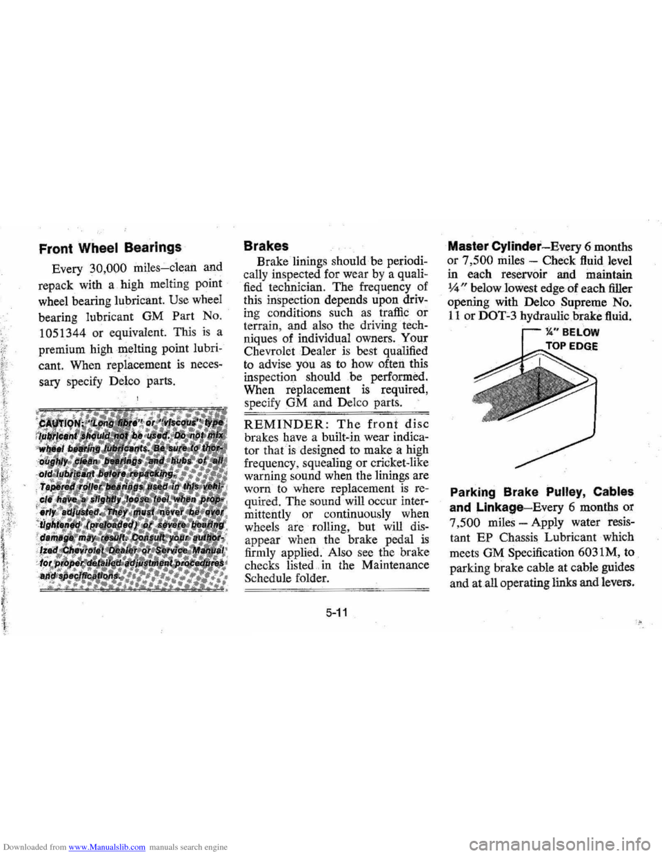
Master Cylinder-Every 6 months
or
7,500 miles -Check fluid level
in each reservoir and maintain
14" below lowest edge-of each filler
opening with Delco Supreme No.
liar DOT-3 hydraulic brake fluid.
11." BELOW
TOP EDGE .k:::O"',
Parking Brake Pulley, Cables
and Linkage-Every 6 months or
7
,500 miles -Apply water resis
tant EP Chassis Lubricant which
meets GM Specification 6031M, to
parking brake cahle at cable guides
and at all operating links and levers.