1976 CHEVROLET MONTE CARLO heater
[x] Cancel search: heaterPage 24 of 102
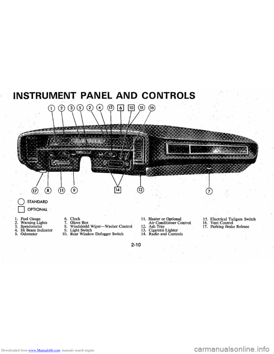
Downloaded from www.Manualslib.com manuals search engine INSTRUMENT PANEL AND CONTROLS
o STANDARD
o OPTIONAL
1. Fuel Gauge 2. Warning Lighls 3. Speedometer 4. Hi Beam Indicator 5. Odometer
6. Clock 7. Glove Box 8. Windshield Wiper-Washer COntrol 9. Light Switch to. Rear Window Defogger Switch
11. Heater or Optional
Air Conditioner Control
12. Ash Tray 13. Cigarette Lighter 14. Radio and Controls 1
5 . Electrical Tailgate Switch
16. Vent Control 17. Paridng Brake Release
2-10
Page 32 of 102
Downloaded from www.Manualslib.com manuals search engine vides ventilation . coillfort , made
possible
by the additionaf air veilt
provisions ' in the rear 1:>ody lock
pillar. Another feature of the
sys
tem is continuous low:speed opera
tion of the heater and air condi
tioner blower , resulting in an un
interrupted
supply of outside air
flOw into the car whenever the
ignition switch is.on. With
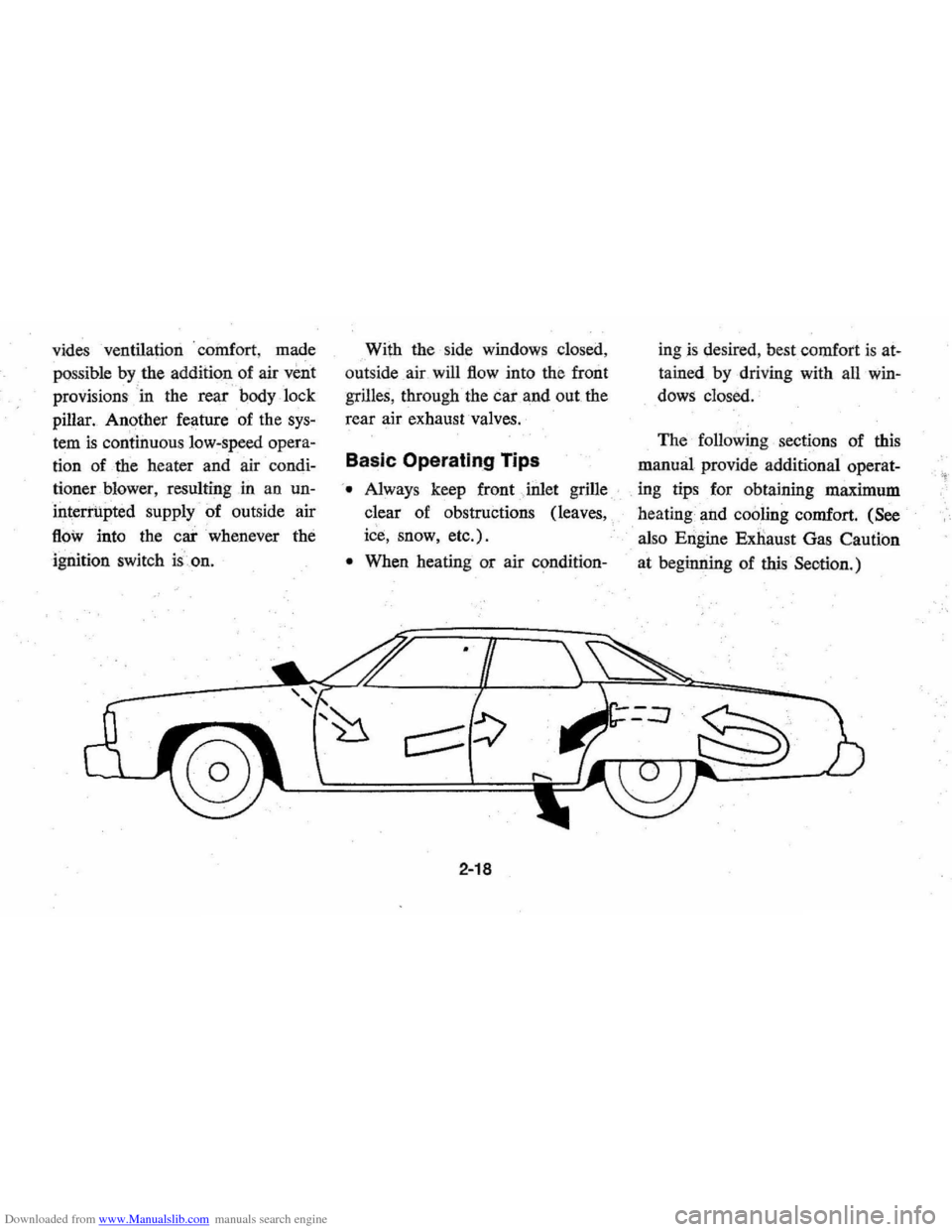
the side windows closed,
out side air will
flow into the front
grilles, through the car and out the
rear air exhaust valves.
Basic Operating Tips
'. Always keep front Jnlet grille
clear of obstructions (leaves,
ice, snow, etc.).
• When heating or air condition-
2-18
ingis desired , best comfort is at
tained by driving with all win
dows closed.
The following sections of this
manual provide additional operat-
. ing tips for obtaining maximum
heating and
cooling comfort. (See
also Engine Exnaust Gas Caution
at beginning of
this Seotion.)
Page 33 of 102
Downloaded from www.Manualslib.com manuals search engine Heater
The defrosting and
defogging
systenl assists in provid,
ing good visibility through desig
nated areas of the windshield under
most
inClement'Weather conditions.
For immediate operation of the ve
hicle, the windshield should be
scraped clear.
'
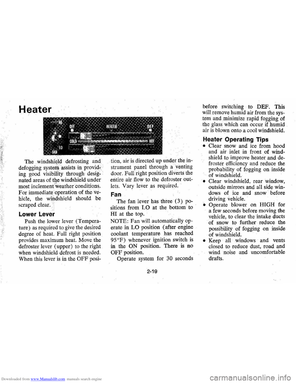
Lower Lever
Push the lower lever (Tempera
ture) as required to,give the desired
degree of heat. Full right position
provides maximum heat.
Move the
defroster lever (upper) to the right
when windshield defrost
is needed.
When this lever
is in the OFF posi- tion,
air is directed
up under the in
strument panel through a'venting
door, Full right position diverts the
entire air
flow to the defroster out
lets, Vary
lever as required.
Fan
The fan lever has three (3) po
sitions from LO at the bottom to
HI at the top.
NOTE: Fan will automatically op
erate in LO position (after engine
coolant temperature has reached
95
OF) whenever ignition switch is
in the ON position. There is no
OFF position.
Operate system for
30 seconds
2-19
before switching to DEF. This
will remove humid air from the
sys
tem and ,minimize rapid fogging of
the glass which can occur
if humid
air is blown onto a coo l windshield.
Heater Operating Tips
• Clear snow and ice from hood
and air inlet in front
of wind
shie ld to improve heater and de
frost er efficiency and reduce the
probability of fogging on inside
of windshield.
• Clear windshield, rear window,
outside
mirrors , and all side win
dows of ice ,and snow before
driving vehicle.
• Operate blower on HIGH for
a few seconds before moving the
vehicle, to clear the intake ducts
of snow to further reduce the
pos sibili
ty of fogging on inside
of windshield.
• Keep all windows and vents
clo sed to reduce dust, road and
wind noise and uncomfortable
drafts .
Page 34 of 102
Downloaded from www.Manualslib.com manuals search engine • For most satisfactory heater op
eration and air circulation , oper
ate fan on low or medium speeds
for normal operation and high
s peeds for quick warm -up and
during extremely low
tempera
tures.
• For adeq uate rear sea t he ating,
the area beneath the front seat
mus not be block ed by carpet
ing, rags, paper or oth er mate
rial and fan sh ould operate on
high blower.
Rear Window Defroster
To ensure clear vision through
the rear
window during inclem ent
weather , the Rear Window
De
froster is optionally available. This
unit dr
aws. in air from the pas
senger compart ment and directs it
aga inst the back window to remove
frost or moisture. Its blower h
as a
two-speed control switch on the
instrument panel.
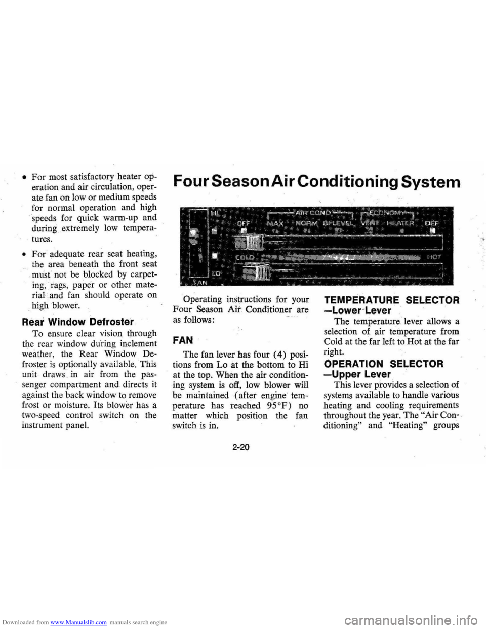
Four Season Air Conditioning System
Operating instructions for your
Four Season Air Conditioner are
a s follows:
FAN
The fan lever has four (4) posi
tions from Lo at the bottom to Hi
at the top. When the air
condition
ing system is off, low blower will
be maintained (after engine
tem
perature has reached 95°F) no
matter which positi on the fan
switch is in.
2-20
TEMPERATURE SELECTOR
-Lower~Lever
The temperature ' lever allows a
selection of air temperature from
Cold at the far left to Hot at the far
right.
OPERATION SELECTOR
-Upper Lever
This lever prov ides a selection of
systems available to handle various
heating and cooling requirements
throughout the year.
The " Air Con-,
ditioning"
an d "He ating" groups
Page 35 of 102
Downloaded from www.Manualslib.com manuals search engine have several positions which im
prove the effectiveness of the sys
tem for various demands.
• Off-The system operates on low
blower regardless of fan switch
position with air discharged into
vehicle
through ,beater outlet.
• Max A/C-Air from the passen
ger compartment is recirculated
through the
system (with some
outside air) and discharged
from
the upper outlets. The max. Ale
position, with Temp, lever in Full
COLD,
is us~d when maximum
cooHng is required under condi
tions of high temperature and
humidity. High fan speed
is auto
matically attained in
this position.
• Norm A/C-Outside air is passed
through the system and dis
charged through the upper out
lets. This position is recommend-
ed for most air,conditioning
situations because of reduclld
blower noise and reduction of
cigarette smoke within the
vehi
cle. Fan speed and tempering,
may
be varied as required.
• Bi-Level A/C-Outside air is de
livered from the heater lower
outlet and the defroster duct and
upper outlets to provide comfort
and keep the windshield and side
glass clear under low fogging
conditions.
• "Economy Ranges" ~ These
positions, VENT
and HEATER,
are recommended
for greater
economy in vehicle operation.
The
AIC compressor will not op
erate in either of these positions.
• Vent -Outside air is passed
through the system and dis-
2-21
charged frorn the upper outlets.
This position
is provided for cool
to rnoderate weather when
refrig
eration is not required. Fan speed
.. and Temp. can be adjusted as
required.
• Heater-Outside air is delivered
through the heater outlet and
with some air through the
de
froster outlets .. Temperature may
be adjusted
as required. This
position
is recommended for most
winter driving.
• Oef -Outside air is delivered
through the defroster outlets and
some air through the floor
out
lets. Temperature and blower
speeds may be adjusted
wire
quired. This position isrecom
mended for conditions of severe
fogging and icing only.
Page 36 of 102
Downloaded from www.Manualslib.com manuals search engine Air Conditioning Comfortron System
The system will run at increased
. capacity
until the pre-set tempera
~
~ ~ OFF .00_:;;::;
• • • • • so i Ii
(U·LIEVEL OIEF
• • "I
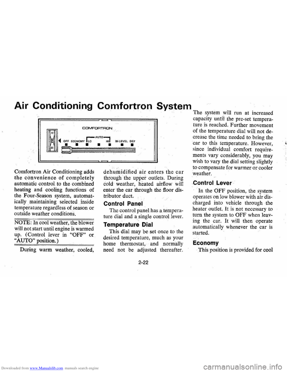
Comfortron Air Conditioning adds
the convenience of completely
automatic control. to the combined
heating and cooling functions of
the Four-Season system,
automat
ically maintaining selected inside
temperature regardless of season or
outside weather conditions.
NOTE: In cool weather, the blower
will not start until engine is warmed
up . (Control lever in
"OFF" or
"AUTO" position.)
During warm weather, cooled,
dehumidified air enters the car
through the upper outlets. During
cold weather, heated airflow will
enter the car through the floor
dis
tributor duct.
Control Panel
The control panel has a tempera
ture dial and a single control lever.
Temperature Dial
This dial may be set once to the
desired temperature , much
as your
home thermostat, and normally
need not be adjusted thereafter.
2-22
ture is reached. Further movement
of the temperature dial will not
de
crease the time needed to bring the
car to this temperature . However,
since individual comfort
require
ments vary considerably, you may
wish to vary the dial setting slightly
to compensate for warmer
or cooler
weather.
Control .Lever
In the OFF position, the system
operates on low blower with air
dis
charged into vehicle through the
heater outlet.
It is not necessary to
turn the system to
OFF when leav
ing the car. It will then operate
automatically whenever the car is
started.
Economy
This position is provided for cool
Page 50 of 102

Downloaded from www.Manualslib.com manuals search engine 0: K.TO JUMP START
~ DARKENED INDICATOR WITH GREEN DOT .. . •• BATTERY CHARGE OK • FLUID LEVEL OK
Jump Start Procedure:
1. Wear eye protection and remove
rings, metal watch bands, and
other metal jewelry.
3-3
2. Set parl<;ing brake ,firmly. I'lace
automatic transmission in
"PARK" in both vehicles (don't
let
vehicles touch); turn ignition
key to LOCK in car with dis
charged battery (Neutral and
"OFF" in cars with,manual
transmissioJl). Also turn off
lights, heater,
ancl all unh~cessary
electrical loads.
3. Attach one end of a jumper
cable
to one battery's positive
terminal (identified
by a red
color, "+1', or "P" on the bat
tery case, post, or clamp), and
the other end
of the same cable
to the positive terminal of the
other battery.
Page 87 of 102
Downloaded from www.Manualslib.com manuals search engine FUSES AND CIRCUIT BREAKER: (Continued) Tho hSDdlomp clrculls are proleded by a dreult breaker In the light Iwitch. An slsc:trlcol overload will cause the lamps to go on and off, or In som~ cOles to remain off'. If this condition deve lo ps, have your
wiring circuit. checked Immediately. In addition to a fuse, the windshield
wiper mot or Is also protected by a circuit breaker. If the motor oyer· heats, due to overk>adlng caused by heClvy snow, etc. tl\e wipers will
remam stopped unltl the motor cools. Also, a c.Irc:uit brea ker. mounted on
the firewall, protects the power window, power seat, and other circuits when vehicle Is so equipp.d. Where current load Is too heavy, the
circuit breake r Intermittently opens and closes, protecting the circuit until the cause Is found and eliminated. Fuses, located in the Junction Block beneath the dash on the driver's .Ide are: Radio, TCS SoL, Hydra·matic Downshift and Anti·Diesel Control, Pulse Wiper System, ChQke Pull Off ........................ . W/S Wiper............. .• . .. . .................... . Stop Lamps, Hazard flasher..... . ......... . Heater, A /C ...... . . .. ' Dir. Sig., B /U lamps, Power Window Relay. Inst.lamps, Heater Dial,::, ..... Inst. Panel Warning Lamps, Gauges, Cruise Control, Rear Defogger Override Relay, SeaL8elt Warning Buzzer. ..... -. c •••••. Warning Buuer, Luggage Lamp, Clock, Courtesy Light, Ligflter,
lOA 25A lOA 25A .. 20A 3 A
lOA
Glove Box Light. . . . .. . . . . . . . ..... 20A Tail lamp, Parking Lamp, License, and Side Marking Lamp... . ..... 20A
An Air Conditioning high blower speed fuse, 30 amps., is located in an In-tine fuse holder runnin g from JUnction block to AI ... Conditioning -relay. Do not Ufe fuses of higher amperage rating than those recommended
obove. Fusible ,
LInks are in(:orporated into 'he wiring system. These are wires of such a gauge that they will fuse (or melt) before damage occun to an _ent ire wiring harn ess in tile even' of an electrical
overload. See your Chevrole t Deal er if fusible link re placement
becom es necessary.
BULB SPECIFICATIONS Heodlamp Unit Outer-High Beam ..........•..•.. Low 8eam .... · .•.••..••....
Inner -High Beam .......... , . •.. .. Parking lamp and Front Directional Signal. .......••... Toil and Stop Lamps Re,ar Directianal Slgn(ll .......•..... license Plate Lamp ............•..... Back.up Lamp ................•.••.. Glo .... Comportment lamp .•..••.....• Indicotor lamps Clock lamp Temperature Indicdtor Lamp 011 Pressure Indica'tor lamp Generator Indicator lamp Hi-880m Indkator lamp Auto. Trans. Quadrant Lamp
Directional Signal Indicator Lamp
Brake System W,a ,rn!ng Lamp Seat Belt Warning Lamp oOor Open Warning Lamp Inshvmen' Panel Ou.ter lamps. Sid. Morker-FrOl1i ................. . Side Marker-Rear ................. . Heater, Ale COntrol Panel Lamp .....•.
D ome Lamp ....................... . lU9t1oge Compartment Lamp ......... . Underhood lamp ................... . Courtesy Lamp ..................... .
Radio Dial Lamp (All exe. Stereo ond Tape player) . . ................ . RadiO, Oial Lamp (Stereo and Tape player) .................... .
Reading lamp ..................•... Radio Indicator .......••..••.•.••...
6-3
Can_uea power Humb ...
37Y~W 4000 55W (S.ale~, Beom)
37V1W 5001 (Sealed Beam)
24-2.2 11S7NA
32-3 1157 3 168
32 I J 56 2 1891
2 194
3 168
2 194
2
194
2 1895
12 211·2or211al 15 1003 15 93
6 631
3 1816
2 564 15 1004 I 66