1976 CHEVROLET MONTE CARLO heating
[x] Cancel search: heatingPage 26 of 102
Downloaded from www.Manualslib.com manuals search engine ble'can be located and corrected .
. Driying the car with low oil pillS'
sure can:cause · serious ' engine
damage.
Genera~orlndicator Light
The red light will go on when
the
ignition key is in the "on " posi,
tion, b~f before the engine is
started.'J\fter the engine starts, the
light .
sho'uld go out and remain out.
If the Hght remains on when engine
is runlling, have your Authorized
Chevrolet Dealer locate and cor,
reCI the trouble as soon as possible,
Engine Temperature
Indicator Light
, This indicator light is provided
in the instrument cluster to quickly
warn
of an overheated engine. With
the ignition switch in the
5T AR T
position, the red TEMP indicator
will light to let you know that it is
operating properly. When
the engine
is started , the
red light will go out immediately,
It will light up at no other time
unless for some reason the engine
.
reaches a dangerously high oper,
atingtemperature. If the light
comes on during
extreme driving
conditions, such
as an extended
idle, turn
off the air conditioner (if
used }.and run the engine slightly
faster than
idle. speed with the
transmission in neutral gear .
If the
light does not go
off within a short
period of time
(F2 minutes), then
tum the engine off until the cause
of the.
overheating is corrected;
Glance at the
Ins.trument cluster
frequently as you drive to see if
this light
is on. '
Brake System Warning
Light
.
The service .. brake system is a
dual system designed
so that. one
part will provide some braking
2-12
action in the event of loss of hy'
draulic pressure in the other part of
the system.
If the ,warning light
labeled
"BRAKE," located in the
speedometer face, comes on .and
stays on when the ignition
is on and
'after · the brakes have been firmly
applied, it may indicate that
there
is a malfunction in one part of the
brake system.
'
•
As ~ reminde;, the light is de,
signed:to
come on with the park,
ing brake applied and the ignition
on.
• The light is also designed to
come on, during ;engine starting
to verify that the bulb is operating
. properly.
• Have system repaired '. if light
does not come
on' during check.
• This warning light, is not a sub
stitute for the visual check of
brake fluid level required
as part
of normal maintenance.
Page 32 of 102
Downloaded from www.Manualslib.com manuals search engine vides ventilation . coillfort , made
possible
by the additionaf air veilt
provisions ' in the rear 1:>ody lock
pillar. Another feature of the
sys
tem is continuous low:speed opera
tion of the heater and air condi
tioner blower , resulting in an un
interrupted
supply of outside air
flOw into the car whenever the
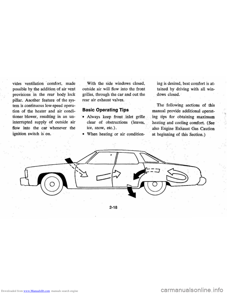
ignition switch is.on. With
the side windows closed,
out side air will
flow into the front
grilles, through the car and out the
rear air exhaust valves.
Basic Operating Tips
'. Always keep front Jnlet grille
clear of obstructions (leaves,
ice, snow, etc.).
• When heating or air condition-
2-18
ingis desired , best comfort is at
tained by driving with all win
dows closed.
The following sections of this
manual provide additional operat-
. ing tips for obtaining maximum
heating and
cooling comfort. (See
also Engine Exnaust Gas Caution
at beginning of
this Seotion.)
Page 34 of 102
Downloaded from www.Manualslib.com manuals search engine • For most satisfactory heater op
eration and air circulation , oper
ate fan on low or medium speeds
for normal operation and high
s peeds for quick warm -up and
during extremely low
tempera
tures.
• For adeq uate rear sea t he ating,
the area beneath the front seat
mus not be block ed by carpet
ing, rags, paper or oth er mate
rial and fan sh ould operate on
high blower.
Rear Window Defroster
To ensure clear vision through
the rear
window during inclem ent
weather , the Rear Window
De
froster is optionally available. This
unit dr
aws. in air from the pas
senger compart ment and directs it
aga inst the back window to remove
frost or moisture. Its blower h
as a
two-speed control switch on the
instrument panel.
Four Season Air Conditioning System
Operating instructions for your
Four Season Air Conditioner are
a s follows:
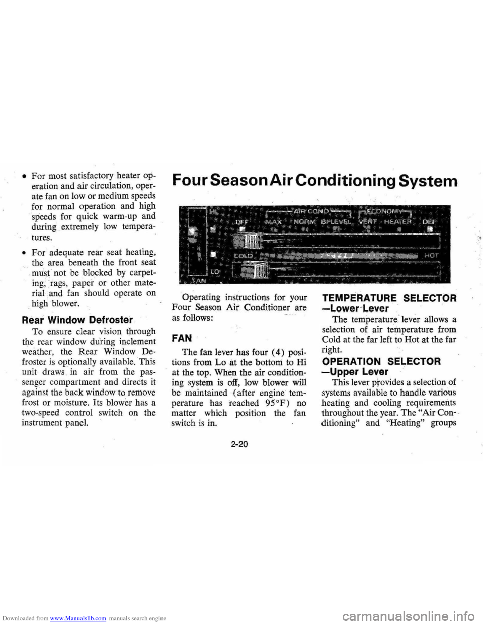
FAN
The fan lever has four (4) posi
tions from Lo at the bottom to Hi
at the top. When the air
condition
ing system is off, low blower will
be maintained (after engine
tem
perature has reached 95°F) no
matter which positi on the fan
switch is in.
2-20
TEMPERATURE SELECTOR
-Lower~Lever
The temperature ' lever allows a
selection of air temperature from
Cold at the far left to Hot at the far
right.
OPERATION SELECTOR
-Upper Lever
This lever prov ides a selection of
systems available to handle various
heating and cooling requirements
throughout the year.
The " Air Con-,
ditioning"
an d "He ating" groups
Page 36 of 102
Downloaded from www.Manualslib.com manuals search engine Air Conditioning Comfortron System
The system will run at increased
. capacity
until the pre-set tempera
~
~ ~ OFF .00_:;;::;
• • • • • so i Ii
(U·LIEVEL OIEF
• • "I
Comfortron Air Conditioning adds
the convenience of completely
automatic control. to the combined
heating and cooling functions of
the Four-Season system,
automat
ically maintaining selected inside
temperature regardless of season or
outside weather conditions.
NOTE: In cool weather, the blower
will not start until engine is warmed
up . (Control lever in
"OFF" or
"AUTO" position.)
During warm weather, cooled,
dehumidified air enters the car
through the upper outlets. During
cold weather, heated airflow will
enter the car through the floor
dis
tributor duct.
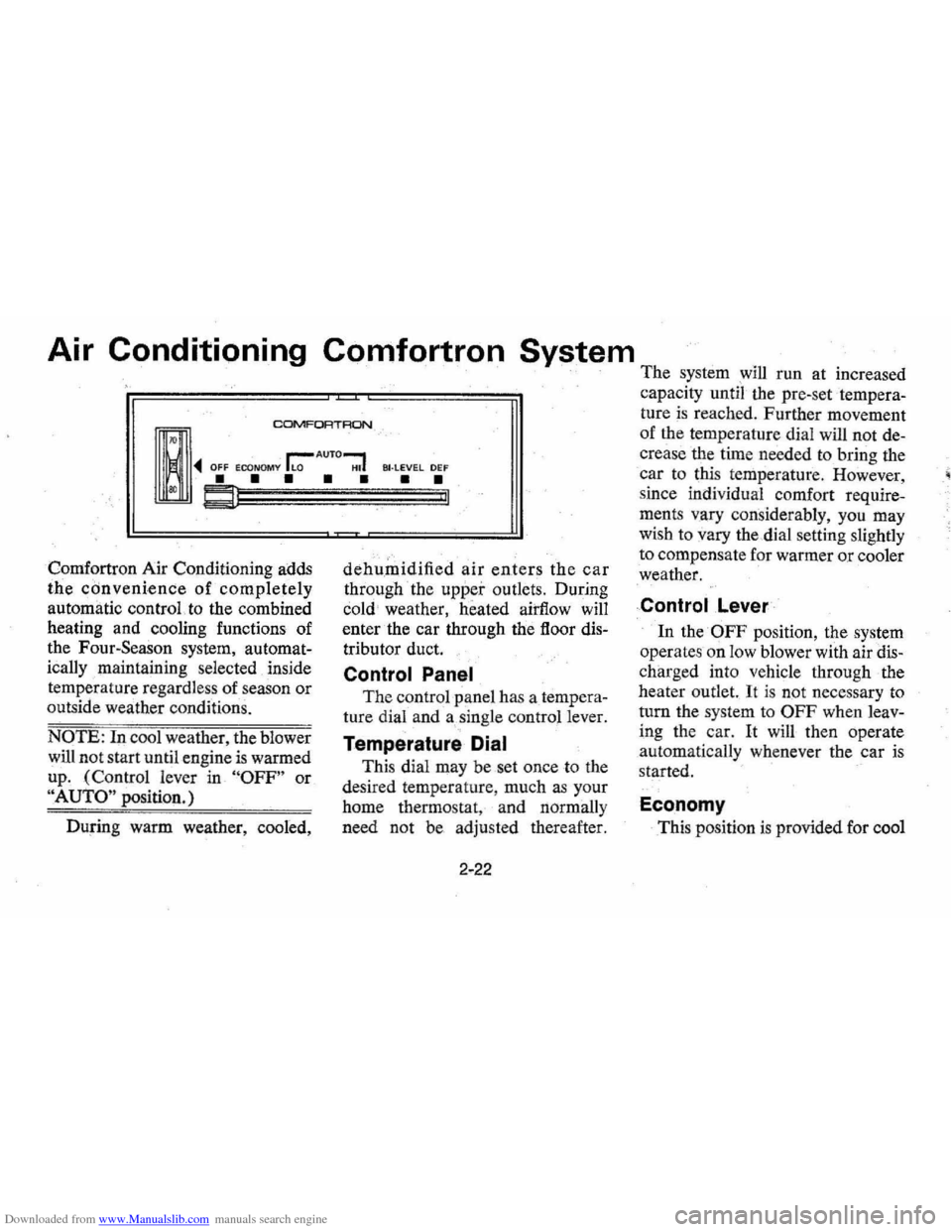
Control Panel
The control panel has a tempera
ture dial and a single control lever.
Temperature Dial
This dial may be set once to the
desired temperature , much
as your
home thermostat, and normally
need not be adjusted thereafter.
2-22
ture is reached. Further movement
of the temperature dial will not
de
crease the time needed to bring the
car to this temperature . However,
since individual comfort
require
ments vary considerably, you may
wish to vary the dial setting slightly
to compensate for warmer
or cooler
weather.
Control .Lever
In the OFF position, the system
operates on low blower with air
dis
charged into vehicle through the
heater outlet.
It is not necessary to
turn the system to
OFF when leav
ing the car. It will then operate
automatically whenever the car is
started.
Economy
This position is provided for cool
Page 37 of 102
Downloaded from www.Manualslib.com manuals search engine (
-t·,
t "7,' ' , ' .
to moderate weather when refriger
ation is not required.
During warm weather the system
will
go into operation almost im
mediately, but cold weather opera
tion will be delayed until the en
gine warms up enough to supply
heat
to the system. The tempera- .
ture and blower speed are auto
matically controlled with the
excep
tion that the AIC compressor will
not operate. In cold weather,
im
mediate blower operation can be
obtained in the
DEF position.
Normal Operation-Set the lever
to
AUTO for completely automatic
in-car temperature control. This
setting allows the system
to utilize
various blower: speeds , resulting in
low to moderate airflow.
Placing the lever in the Lo posi
tion is the same as AUTO setting
except the blower wi\l remain at
low speed.
When greater airflow
is desired or
in severe weather extremes, . set
the lever to HI. The system , still
under automatic
·control, will now
make use of high blower speed
only, resulting in high airflow for
rapid cool
dOwn or heating .
BI-Level Operation
On cool but sunny days . the
Comfortron system
will provide
warm air to the floor and cooler air
out of the upper outlets thus
pro
viding a warm floot without 'exces
sive rise in breath level tempera
ture. Under extremely bright sun
conditions, the system may shift
into bi-level operation at relatively
low outside temperatures in order
to maintain the temperature set on
the dial.
If cool air from upper out
lets is objectionable, adjust upper
outlets
as desired.
For window defogging -Move
the lever
to BI-LEVEL to divert a
portion of the conditioned air
through the defroster ducts and up-
2-23
per outlets when interior window
fogging
is encountered.
For windshield de-icing -With
the lever in the
DEF position the
system directs most of the airflow
at full heat and high blower speed
through the defroster ducts.
Some
airflow is also directed to the floor.
Air-Conditioner
Operating Tips
Close all windows and vents
when operating air system except
for the
first few minutes of opera
tion when the car interior is very
hot. Close the windows
as soon as
the excessively heated air has es
caped.
Four season System and
Comfort ron Conditioned
Air
Outlets
The twin barrel type center out·
let may be rotated or vanes turned
to direct air
flow in direction de
sired .
Page 42 of 102

Downloaded from www.Manualslib.com manuals search engine level the car under various loaded
conditions. Air
is added to the
rear shock absorbers,
as needed,
through an air valve located
in the
rear bumper
as shown in the illus
tration. A minimum pressure of
10-\5 psi should be maintained at
all times. After the car is loaded ,
pressure may be increased until the
rear of the vehicle returns to the
normal designed riding height, but
not to exceed
90 psi.
Station Wagon
,t tor some reason, It Is necessary to drive with the tailgat. window open, the
Reclining Seat Back
Caprice
Models .
The passenger seat back can be
reclined rearward approximately
20 degrees from normal position
by lifting the control lever at the
outboard side
of the passenger's
following 'precautions should be observed:
• Close all other windows.
• Adjust heating or cooling system to torce outside air. Into, car 8S follows:
1. On $fatlon Wagons not equipped with' ai' conditlon;ng, set Ian to medium Ot high speed and upper control lever to any position except OFf. 2. On Station Wagons equipped with manua' air conditioning, set 'an to
2-28
seat cushion and. exerting rearward
pressure
or with no pressure on the
seat back
allow seat back to
return forward.
medium or, high sPded, upper control lever to any posWan except OFF, and lower control lever to any position
except extrem~ lett COLD.
3 . On Station Wagons equipped with a.utomaUc .'r conditioning. set ~ontrol lerer to HI except in hot weather, in which cas., set 'ever to AUTO.
• On starlon wagons equipped with ouiside air rents under or In Instrument panel, open venrs fully.
•
Page 70 of 102
Downloaded from www.Manualslib.com manuals search engine --;
protection at-20op (-2S0C) or
below to ensure pro;tection against
corrosion and loss
of coolant
from boiling even though freezing '
temperatures are not expected.
• Add ethylene glycol base coolant
that meets
GM Specification
IS99-M when coolant additions
are required because of coolant
loss
Or to provide additional pro"
tection against freezing at tem_
peratures lower than _20oP,
(-2S0C),' and in Canada to
_35°P ( -3JOC).
NOTE: AlcOhol Or methanol base
coolants or plain water are not
recommended for your vehicle at
any time.
Radiator Pressure Cap
The radiator cap, a 15 lb. pres
sure type, must be installed tightly,
otherwise coolant may be lost and
damage
, to engine may result from
overheating. Radiator pressure caps
should
be chef'ked periodically for
' proper operation.
If replacement is
required specify·AC.
Thermostat
The cooling system is protected
and controlled by a thermostat that
maintains a satisfactory
" engine
operating temperature . This
ther
mostat is installed in the engine
coolant outlet
arid is designed for
continuous use through both winter
and
s ·ummer. When replacement is
necessary, Delco parts are recom
mended.
5-9
CHASSIS ITEMS
Rear Axle Lubricant
Standard -
Every 6 months or
7,500 miles , whichever occurs first,
check lubricant level and add
lubri
cant, if necessary, to fill to level of
filler plug hole.
Use SAE SOW or
SAE SOW-90 GL-5 Gear Lubricant.
cant.
(Por vehicles operated in
Canada, use
SAE SOW Gear Lubri
cant.)
Posilraction -Drain and refill
after
the first 15,000 miles then
maintain same
as standard axle but
use only the special positraclion lu-·
bricant available from yo ur Chev
roletDealer , part number 1051022.
Rear Universal Joint Fitting
-Except Wagons
Every 6 months or 7,500 miles
lubricate universal joint with water
resistant
EP Chassis Lubricant
Part number 1050679 which meets
GM Specification 6040M.
Page 93 of 102
Downloaded from www.Manualslib.com manuals search engine Converter, Catalylic .............. .5-22, 5-23 Cooling System Care ............................ 5·7 Coolant "Recommendation ....... ;. 5-7 Overheating Caution. . . . . . . . . . . . .. 3-4 Courtesy Lights ............ ." ..... , 6-2.317 Cowl Air Inlets ...... , ...... , ...... . Cruise Control ............. -. . . . . . .. 2-6 Dealer. Assistance ........... -;. ...... 6-4 Defogger, Rear Window ......... , . .. 2-20 Defroster, Defogger, Windshield ...... 2-19 Dimensions, Vehicle ......• -', ........ ' 6-1 Dimmer Switch, Headlarnp : ........ ' 2-9 Directional Signals .. , . , ...... , . . . . .. 2-5 Door Locks... ....... ............ .. 1·2 Power Doo r Locks .... , •...••...... 2-27 prive Belts, Engine. . . . . . . . . . . . . . . .. 5-4 Driver ' Sj;at Adju stment; .......... , ,..... 1-2 ," D~titfy Conditions. Operating Unqer. .. 5-2 ~ Economy Gauge, Fuel...... .. ..... .. 2~14 Electric Clock ................ , .. , .. 2~15 Electrical System Battery ....................... 5·13. 6-1 Bulbs ........................... 6-3 Fuses ... " ...................... 6-3 Generator Indicator Light ..•...... 2~12 Emergency, In Case Of, . ' . , .. ~ . . . . .. 3~ 1
Brake Warnin~ Light ............. ' 2~12 Generator Indicator Not Charging.. 2-12 Hazard Warning Flasher ........... 3-1 Jacking To Change Wheels......... 3·4 Jump Starting with Auxiliary Battery 3-2
Overheated Radiator ............ ,. 3-4 Pushing To Start ................ ' 3-2 Spare Tire .... , . . . . . . . . . . . • . • . . .. 3-4
Towing .. , ...............•.... , ., 3-1
Engine
Cooling. . . . .. .. .. . .. .. .. .. .. .... 5-7 Exhaust Gas Caution, ........•... , 2-1 Flooded , Starting Procedure. .•• . . .. 2-3 Overheating .. , .. , . .. . . . . . . . . . . . .. 3-4 Serial Number.. .. .. .. .. .. .. .. .... 6-1 Specificati ons ......... , ....... , , .. 6-2
Starting .................. ....... 2·3 Temperature Light.. , ........ -. .. ,. 2-12
Engine Oil Capacity .... ' .... , .... , ....•••. ',," 6-1 Change Interval .......• ' .. , • . . . .. 5-2 Dip Stick........ ........ ........ 5-2 Filter .......... .-. . . . . . . . . . . • . . . .. 5-2
Pressure Indicator .•.......••.... , 2-11 Recommendation. . . . . . . . . . . . . . . .. 5-3 Ethylene Glycol Coolant... . . . . . . . . .. 5·7 Exhaust Gas caution.... .... ...... .. 2 .. 1
Driving With Trunk Open. ........ 2-1 Exhau st System Checks ........ ,' .. 2-1 Parked With Engine Running. , .... 2-1 Pulling A Trailer. .............. " 2_1 Exterior Finish and Trim Care. . . . . .. 4-5
Fabric Care.. .. .. .. .. ... .. .. .. .. ... 4-1 Fan Belt ............................. 5-4 Ventilating .•... , ................ , 2-19 Filter, Oil. .... " ................ , . .. 5-2 Finish Care Exterior .......... , . , .. , 4-5 First Few Hundred Miles of Driving .. , ........... ' .... ; . . . . . .. ii
Flammable Cleaning Solvents. . . . . . .. 4-2 Flashers Hazard Warning .... ~. ............ 3-1 Turn Signal. ..... ' ......... , . . . .. 2-5 Flooded. Engin e, Starting. . . . . • . • . . .. 2-3 Floor Controls. .. .. .. .. .. .. .. .. .... 2·8
6-9
Fluid Capacities ........... ·......... 6.1 Fluid Levels
Battery ..... , ......... Inside Back Cover
Brake Master Cylinder., ..... , .... 5-11 Engine Oil .............. , ........ 5·2 Power Steering .. , ......... '" . . .. 5.10 Radiator .................. ,. ,-... , 5-7 Rear Axle ................... '.... 5-9 Transmission ....... , . , ........... , 5-5
Fluid Recommendations
Brake
........................... 5.11 Power Steering, .......... '. -..... ~'. 5-11 Rad.iat~r, : ......... ....... ,.,."., 5-7 TranslOlsslon ....... , . . . . . . . . . . . .. 5·5 Windshield Washer .. , ., ....... ;--.-, 2-15 Fogging, With Air Conditioner ..... " 2-21 Folding Seat Back Latches ... ........ 1·2 Foreign Countries , Operation In .... ,. 1-12 Four Way Hazard Flasher. , . , , ... , ,. 3-1
Front Suspen sion. . . . . . . .. . . . . . . . . .. 5-10 Front Wheel Bearings ... :: ......... ,. 5·11 Fue l (See Gasoline) Fuel Economy Gauge ..... , ... , ,. . .. 2-14 Fumes, Engine Exhaust., ....•..... , .• 2-1 Fuses Cbart ........................... 6-3 Location.... . .. . . . . .. .. . . . . . . . . . . 6-2 Gas Station Information .,. Inside Back Cover Gasoline, Capacities ..... : , , . . . . . . .. 6-1 Do Not Use For Cleaning .. , . , . , ., 4-2 FlUer Cap Location .... Inside Back Cover
Fumes ........................... 2·1 Gauge ........... ,..... .......... 2·11 Low·Lead............ ...... ...... s· Recommendations, .... ,...... .... 5-1 Gauge, FueL .... ,........ .. ........ 2-11 Gearshift Lever... . . . . . . . . . . . . . . . . .. 2·4 Generator Indicator Light ........... 2·12