CHASSIS
I
l
I
I
2
fa
r
o
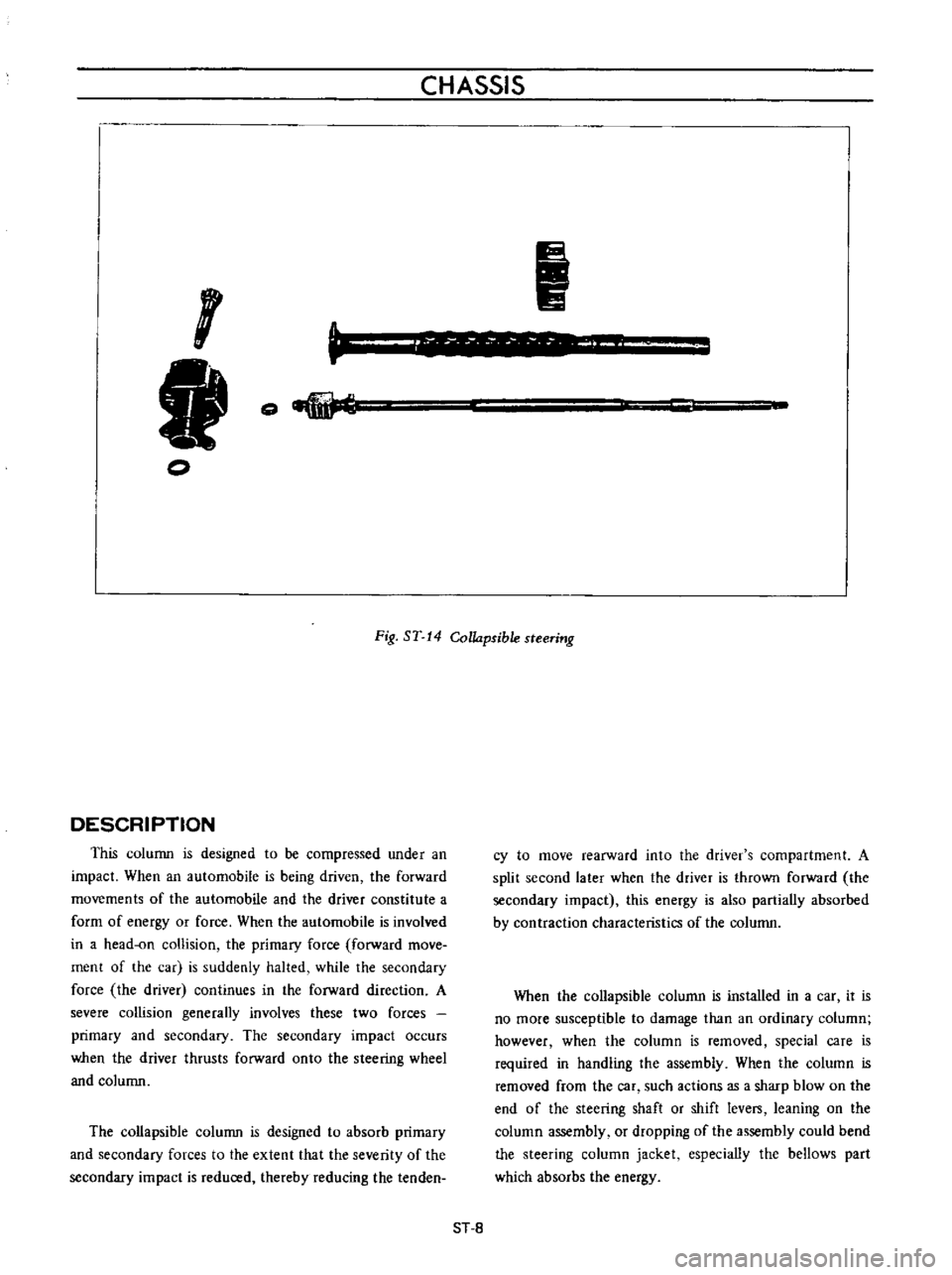
Fig
ST
14
Collapsible
steering
DESCRIPTION
This
column
is
designed
to
be
compressed
under
an
impact
When
an
automobile
is
being
driven
the
forward
movements
of
the
automobile
and
the
driver
constitute
a
form
of
energy
or
force
When
the
automobile
is
involved
in
a
head
on
collision
the
primary
force
forward
move
ment
of
the
car
is
suddenly
halted
while
the
secondary
force
the
driver
continues
in
the
forward
direction
A
severe
collision
generally
involves
these
two
forces
primary
and
secondary
The
secondary
impact
occurs
when
the
driver
thrusts
forward
onto
the
steering
wheel
and
column
The
collapsible
column
is
designed
to
absorb
primary
and
secondary
forces
to
the
extent
that
the
severity
of
the
secondary
impact
is
reduced
thereby
reducing
the
tenden
cy
to
move
rearward
into
the
driver
s
compartment
A
split
second
later
when
the
driver
is
thrown
forward
the
secondary
impact
this
energy
is
also
partially
absorbed
by
contraction
characteristics
of
the
column
When
the
collapsible
column
is
installed
in
a
car
it
is
no
more
susceptible
to
damage
than
an
ordinary
column
however
when
the
column
is
removed
special
care
is
required
in
handling
the
assembly
When
the
column
is
removed
from
the
car
such
actions
as
a
sharp
blow
on
the
end
of
the
steering
shaft
or
shift
levers
leaning
on
the
column
assembly
or
dropping
of
the
assembly
could
bend
the
steering
column
jacket
especially
the
bellows
part
which
absorbs
the
energy
ST
8
ENGINE
WATER
PUMP
The
water
pump
is
a
centrifugal
type
water
pump
with
an
aluminum
die
cast
pump
body
The
volute
chamber
is
built
into
the
front
cover
assembly
and
a
high
pressure
sealing
mechanism
is
adopted
to
prevent
the
water
leakage
and
noise
completely
Note
The
water
pump
must
not
be
disassembled
since
the
bearings
are
shrinkage
fitted
to
their
bores
If
any
part
of
water
pump
is
found
defective
replace
pump
assembly
o
C0026
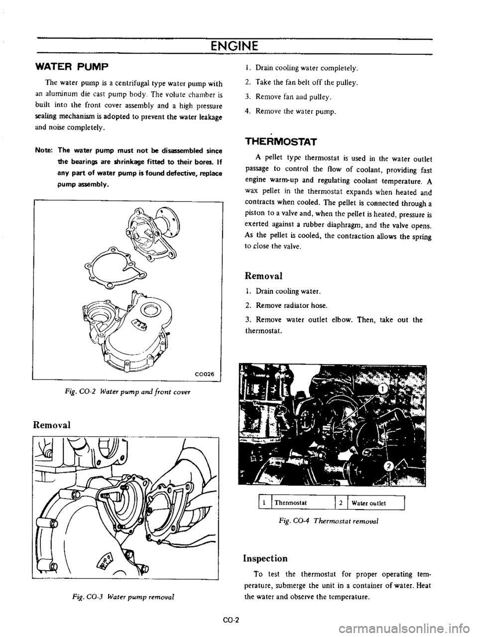
Fig
CO
2
Water
pump
and
front
cover
Removal
Fig
CO
3
Water
pump
removal
Drain
cooling
water
completely
2
Take
the
fan
belt
off
the
pulley
3
Remove
fan
and
pulley
4
Remove
the
water
pump
THERMOSTAT
A
pellet
type
thermostat
is
used
in
the
wa
ter
outlet
passage
to
control
the
flow
of
coolant
providing
fast
engine
warm
up
and
regulating
coolant
temperature
A
wax
pellet
in
the
thermostat
expands
when
heated
and
contracts
when
cooled
The
pellet
is
connected
through
a
piston
to
a
valve
and
when
the
peUet
is
heated
pressure
is
exerted
against
a
rubber
diaphragm
and
the
valve
opens
As
the
pellet
is
cooled
the
contraction
allows
the
spring
to
close
the
valve
Removal
Drain
cooling
water
2
Remove
radiator
hose
3
Remove
water
outlet
elbow
Then
take
out
the
thermostat
11
I
Thermostat
12
Water
outlet
Fig
CO
4
Thermostat
removal
Inspection
To
test
the
thermostat
for
proper
operating
tern
perature
submerge
the
unit
in
a
container
of
water
Heat
the
water
and
observe
the
temperature
CO
2