1973 DATSUN B110 tire pressure
[x] Cancel search: tire pressurePage 154 of 513
DESCRIPTION
MAINTENANCE
AND
SERVICE
Tire
inflation
Tubeless
tire
repair
Wheel
repair
Wear
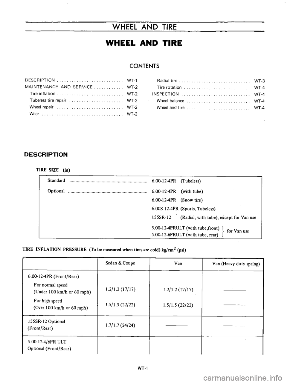
DESCRIPTION
TIRE
SIZE
in
Standard
Optional
WHEEL
AND
TIRE
WHEEL
AND
TIRE
CONTENTS
WTl
WT2
WT2
WT2
WT2
WT2
Radial
tire
Tire
rotation
INSPECTION
Wheel
balance
Wheel
and
tire
6
00
12
4PR
Tubeless
6
00
12
4PR
with
tube
6
00
12
4PR
Snow
tire
6
00S
12
4PR
Sports
Tubeless
155SR
12
Radial
with
tube
except
for
Van
use
5
00
12
4PRULT
with
lube
front
for
Van
use
5
00
12
jPRULT
with
tube
rear
TIRE
INFLATION
PRESSURE
To
be
measured
when
tires
are
cold
kg
cm2
psi
6
00
I
2
4PR
Front
Rear
For
normal
speed
Under
100
km
h
or
60
mph
For
high
speed
Over
100
km
h
or
60
mph
155SR
12
Optional
Front
Rear
5
00
I
2
4
6PR
ULT
Optional
Front
Rear
Sedan
Coupe
1
2
1
2
17
17
1
5
1
5
22
22
1
7
1
7
24
24
Van
Van
Heavy
duty
spring
1
2
1
2
I
7
17
1
5
1
5
22
22
WTl
WT
3
WT
4
WT
4
WT
4
WT
4
Page 155 of 513
CHASSIS
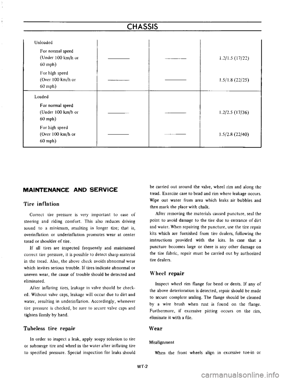
Unloaded
For
normal
speed
U
nder
100
km
h
or
60
mph
F
or
high
speed
Over
100
km
h
or
60
mph
Loaded
For
normal
speed
Under
100
kmlh
or
60
mph
For
high
speed
Over
100
kmlh
or
60
mph
MAINTENANCE
AND
SERVICE
Tire
inflation
Correct
tire
pressure
is
very
importan
t
to
ease
of
steering
and
riding
comfort
This
also
reduces
driving
sound
to
a
minimum
resulting
in
longer
tire
that
is
overinfla
lion
or
underinflation
promotes
wear
at
center
tread
or
shoulder
of
tire
If
all
tires
are
inspected
frequently
and
maintained
correct
tire
pressure
it
is
possible
to
detect
sharp
material
in
the
tread
Also
the
above
check
avoids
abnormal
wear
which
invites
serious
trouble
If
tires
indicate
abnormal
or
uneven
wear
the
cause
of
trouble
should
be
detected
and
eliminated
After
inflating
tices
leakage
in
valve
should
be
check
cd
Without
valve
caps
leakage
will
occur
due
to
dirt
and
water
resulting
in
underinOation
Accordingly
whenever
tire
pressure
is
checked
be
sure
to
secure
valve
caps
and
tighten
firmly
by
hand
Tubeless
tire
repair
In
urder
to
inspect
a
leak
apply
soapy
solution
to
tire
or
submerge
tire
and
wheel
in
the
water
after
inflating
tire
to
specified
pressure
Special
inspection
for
leaks
should
12
15
17
22
1
5
1
8
22
25
1
2
2
5
I
7
36
1
5
2
8
22
40
be
carried
out
around
the
valve
wheel
rim
and
along
the
tread
Exercise
care
to
bead
and
rim
where
leakage
occurs
Wipe
out
water
from
area
which
leaks
air
bubbles
and
then
mark
the
place
with
chalk
After
remuving
the
materials
caused
puncture
seal
the
point
to
avoid
damage
to
the
tire
due
to
entrance
of
dirt
and
water
When
repairing
the
puncture
use
the
tire
repair
kits
which
are
furnished
from
tire
dealers
following
the
instructions
provided
with
the
kits
In
case
that
a
puncture
becomes
large
or
there
is
any
other
damage
on
the
tire
fabric
repair
must
be
carried
out
by
authorized
tire
dealers
Wheel
repair
Inspect
wheel
rim
flange
for
bend
or
dents
If
any
of
the
above
deterioration
is
detected
repair
should
be
made
to
secure
complete
sealing
The
flange
should
be
cleaned
by
a
wire
brush
when
rust
is
found
on
the
flange
Furthermore
if
excessive
pitting
occurs
on
the
rim
eliminate
it
with
a
file
Wear
Misalignment
When
the
front
wheels
align
in
excessive
toe
in
or
WT
2
Page 156 of 513
WHEEL
AND
TIRE
toe
out
condition
tires
scrape
the
tread
rubber
off
The
wear
of
tread
appears
feathered
edge
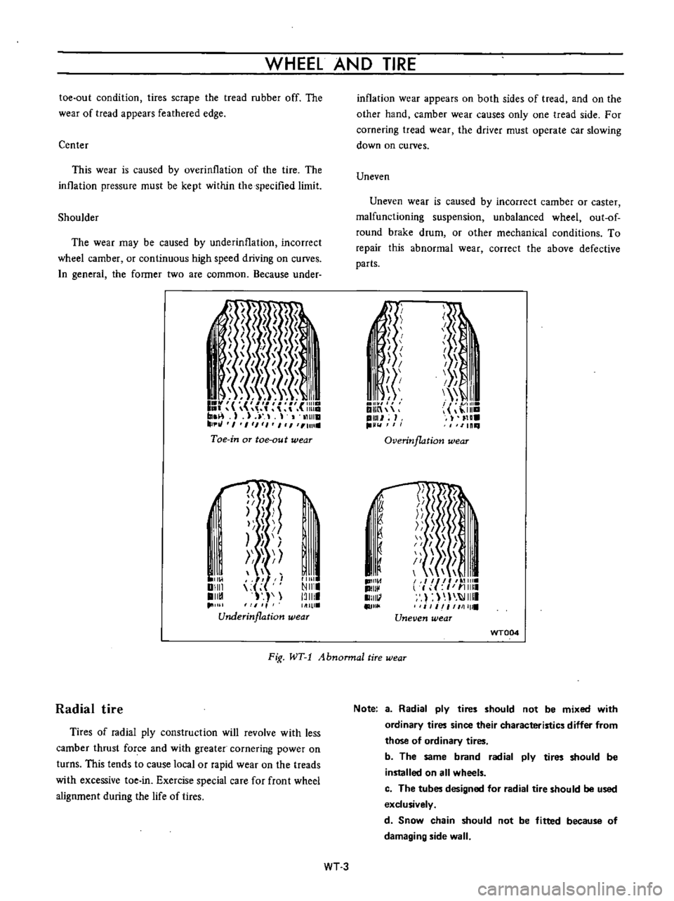
Center
This
wear
is
caused
by
overinllation
of
the
tire
The
inllation
pressure
must
be
kept
within
the
specified
limit
Shoulder
The
wear
may
be
caused
by
underinflation
incorrect
wheel
camber
or
continuous
high
speed
driving
on
curves
n
general
the
former
two
are
common
Because
under
I
I
I
I
1
1111
I
r
r
m
1
J
11
tHlla
tJ
I
1
1
1
I
1
Ull
Toe
in
aT
toe
au
t
wear
l
f
I
II
I
I
I
I
Ill
Ill
Underinflation
wear
I
11
01
DIIII
II
1
11111
NIII
13111
inflation
wear
appears
on
both
sides
of
tread
and
on
the
other
hand
camber
wear
causes
only
one
tread
side
For
cornering
tread
wear
the
driver
must
operate
car
slowing
down
on
curves
Uneven
Uneven
wear
is
caused
by
incorrect
camber
or
caster
malfunctioning
suspension
unbalanced
wheel
out
of
round
brake
drum
or
other
mechanical
conditions
To
repair
this
abnormal
wear
correct
the
above
defective
parts
Ii
I
I
I
I
1
i
f
I
I
I
I
I
III
I
I
11
DlIIn
ilia
pml
H
IlLl
11111
Overinflation
wear
1D1I1
d
II
1I111
II
j
J
1
51
I
I
I
1
il
I
I
II
l
f
I
11
11111
I
IIIII
i
1
iI
1111111
Uneven
wear
f
I
I
u
WT004
Fig
WT
1
Abnonnal
tire
wear
Radial
tire
Tires
of
radial
ply
construction
will
revolve
with
less
camber
thrust
force
and
with
greater
cornering
power
on
turns
This
tends
to
cause
local
or
rapid
wear
on
the
treads
with
excessive
toe
in
Exercise
special
care
for
front
wheel
alignment
during
the
life
of
tires
Note
a
Radial
ply
tires
should
not
be
mixed
with
ordinary
tires
since
their
characteristics
differ
from
those
of
ordinary
tires
b
The
same
brand
radial
ply
tires
should
be
installed
on
all
wheels
c
The
tubes
designed
for
radial
tire
should
be
used
exclusively
d
Snow
chain
should
not
be
fitted
because
of
damaging
side
wall
WT3
Page 158 of 513
WHEEL
AND
TIRE
Note
In
replacing
tire
take
extra
care
not
to
damage
tire
bead
rim
flange
and
bead
seat
Do
not
use
tire
irons
to
force
beads
away
from
wheel
rim
flange
that
is
always
use
tire
replace
ment
device
whenever
tire
is
removed
WT005
2
Discard
when
any
of
the
following
trouble
occurs
I
Broken
or
damaged
bead
wire
2
Ply
or
tread
separation
3
Worn
febric
damage
on
tubeless
tire
4
Cracked
or
damaged
side
wall
etc
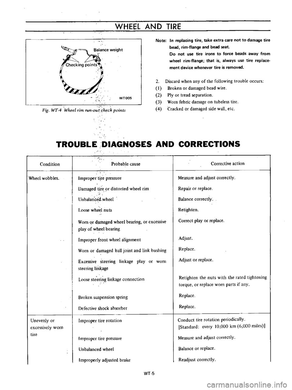
Fig
WT
4
Wheel
rim
run
out
heck
points
TROUBLE
DIAGNOSES
AND
CORRECTIONS
Condition
Probable
cause
Corrective
action
Wheel
wobbles
Improper
t
re
pressure
Measure
and
adjust
correctly
Damaged
tire
9f
distorted
wheel
rim
Repair
or
replace
UnbalanceiLwheel
Balance
correctly
Loose
wheel
nuts
Retighten
Worn
qr
damaged
wheel
bearing
or
excessive
play
of
wheel
bearing
Correct
play
or
replace
Improper
front
wheel
alignment
Adjust
Worn
or
damaged
ball
joint
and
link
bushing
Replace
Excessive
steering
linkage
play
or
worn
steering
lin
age
Adjust
or
replace
Loose
stcerin
linkage
connection
Retighten
the
nuts
with
the
rated
lightening
torque
or
replace
worn
parts
if
any
Broken
suspension
spring
Replace
Defective
shock
absorber
Replace
Unevenly
or
excessively
worn
tire
Improper
tire
rotation
Conduct
tire
rotation
periodically
Standard
every
10
000
km
6
000
miies
Improper
tire
pressure
Measure
and
adjust
correctly
Unbalanced
wheel
Balance
or
replace
Improperly
adjusled
brake
Readjust
correctly
WT5
Page 159 of 513
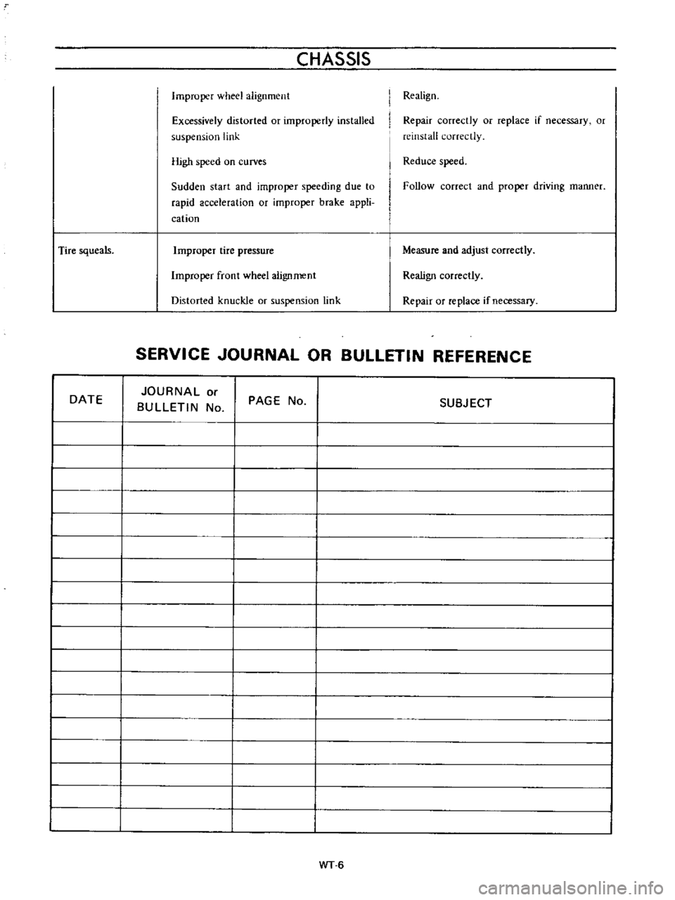
Tire
squeals
DATE
CHASSIS
Improper
wheel
alignment
Excessively
distorted
or
improperly
installed
suspension
link
High
speed
on
curves
Sudden
start
and
improper
speeding
due
to
rapid
acceleration
or
improper
brake
appli
cation
Improper
tire
pressure
Improper
front
wheel
alignment
Distorted
knuckle
or
suspension
link
Realign
Repair
correctly
or
replace
if
necessary
or
reinstall
correctly
Reduce
speed
Follow
correct
and
proper
driving
manner
Measure
and
adjust
correctly
Realign
correctly
Repair
or
replace
if
necessary
SERVICE
JOURNAL
OR
BULLETIN
REFERENCE
JOURNAL
or
BULLETIN
No
PAGE
No
I
I
I
I
I
I
I
I
I
I
I
I
I
I
I
I
I
I
WT
6
SUBJECT
Page 178 of 513
CHASSIS
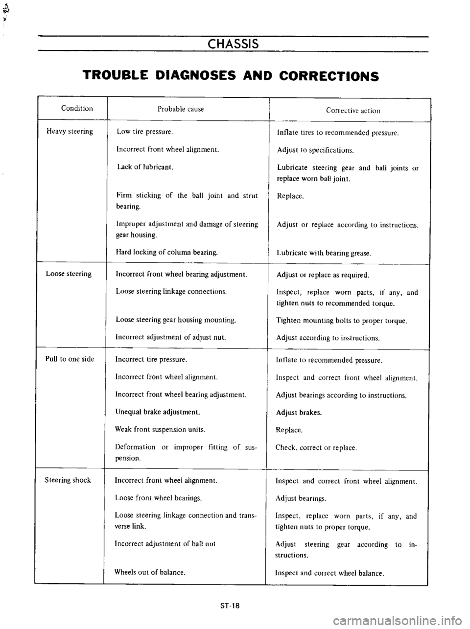
TROUBLE
DIAGNOSES
AND
CORRECTIONS
Condition
Heavy
steering
Loose
steering
PuU
to
one
side
Steering
shock
Probable
cause
Low
tire
pressure
Incorrect
front
wheel
alignment
Lack
of
lubricant
Firm
sticking
of
the
ball
joint
and
strut
bearing
Improper
adjustment
and
damage
of
steering
gear
housing
Hard
locking
of
column
bearing
Incorrect
front
wheel
bearing
adjustment
Loose
steering
linkage
connections
Loose
steering
gear
housing
mounting
Incorrect
adjustment
of
adjust
nut
Incorrect
tire
pressure
Incorrect
front
wheel
alignment
Incorrect
front
wheel
bearing
adjustment
Unequal
brake
adjustment
Weak
front
suspension
units
Deformation
or
improper
fitting
of
sus
pension
Incorrect
front
wheel
alignment
Loose
front
wheel
bearings
Loose
steering
linkage
connection
and
trans
verse
link
Incorrect
adjustment
of
ball
nut
Wheels
out
of
balance
ST
18
Corrective
action
Inflate
tires
to
recommended
pressure
Adjust
to
specifications
Lubricate
steering
gear
and
ball
joints
or
replace
worn
ball
joint
Replace
Adjust
or
replace
according
to
instructions
Lubricate
with
bearing
grease
Adjust
or
replace
as
required
Inspect
replace
worn
parts
if
any
and
tighten
nuts
to
recommended
torque
Tighten
mounting
bolts
to
proper
torque
Adjust
according
to
instructions
Inflate
to
recommended
pressure
Inspect
and
correct
front
wheel
alignment
Adjust
bearings
according
to
instructions
Adjust
brakes
Replace
Check
correct
or
replace
Inspect
and
correct
front
wheel
alignment
Adjust
bearings
Inspect
replace
worn
parts
if
any
and
tighten
nuts
to
proper
torque
Adjust
steering
gear
according
to
in
structions
Inspect
and
correct
wheel
balance
Page 222 of 513
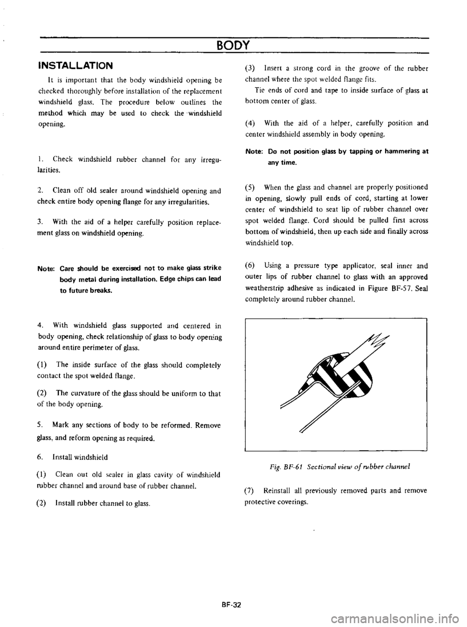
INSTALLATION
It
is
important
that
the
body
windshield
opening
be
checked
thoroughly
before
installation
of
the
replacement
windshield
glass
The
procedure
below
outlines
the
method
which
may
be
used
to
check
the
windshield
opening
Check
windshield
rubber
channel
for
any
irregu
larities
2
Clean
off
bid
sealer
around
windshield
opening
and
check
entire
body
opening
flange
for
any
irregularities
3
With
the
aid
of
a
helper
carefully
position
replace
ment
glass
on
windshield
opening
Note
Care
should
be
exercised
not
to
make
glass
strike
body
metal
during
installation
Edge
chips
can
lead
to
future
breaks
4
With
windshield
glass
supported
and
centered
in
body
opening
check
relationship
of
glass
to
body
ope
rung
around
entire
perimeter
of
glass
I
The
inside
surface
of
the
glass
should
completely
contact
the
spot
welded
flange
2
The
curvature
of
the
glass
should
be
uniform
to
that
of
the
body
opening
5
Mark
any
sections
of
body
to
be
reformed
Remove
glass
and
reform
opening
as
required
6
Install
windshield
I
Clean
out
old
sealer
in
glass
cavity
of
windshield
rubber
channel
and
around
base
of
rubber
channel
2
Install
rubber
channel
to
glass
BODY
8F
32
3
Insert
a
strong
cord
in
the
groove
of
the
rubber
channel
where
the
spot
welded
flange
fits
Tie
ends
of
cord
and
tape
to
inside
surface
of
glass
at
bottom
center
of
glass
4
With
the
aid
of
a
helper
carefully
position
and
center
windshield
assembly
in
body
opening
Note
Do
not
position
glass
by
tapping
or
hammering
at
any
time
5
When
the
glass
and
channel
are
properiy
positioned
in
opening
slowly
pull
ends
of
cord
starting
at
lower
center
of
windshield
to
seat
lip
of
rubber
channel
over
spot
welded
flange
Cord
should
be
pulled
first
across
bottom
of
windshield
then
up
each
side
and
finally
across
windshield
top
6
Using
a
pressure
type
applicator
seal
inner
and
outer
lips
of
rubber
channel
to
glass
with
an
approved
weatherstrip
adhesive
as
indicated
in
Figure
BF
57
Seal
completely
around
rubber
channel
Fig
BF
61
Sectional
view
of
rubber
channel
7
Reinstall
all
previously
removed
parts
and
remove
protective
coverings
Page 226 of 513
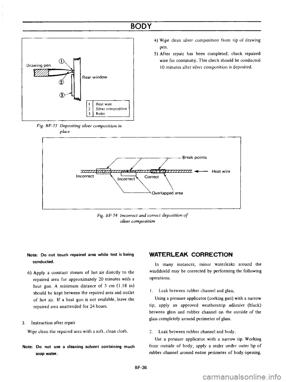
Drawing
pen
ri
Rear
window
L
Ii
r
Heat
wire
2
Silver
Imposition
3
Ruler
Fig
BF
73
Depositi
rg
silver
composition
in
place
BODY
4
Wipe
clean
silver
umposition
trom
tip
of
drawing
pen
5
After
repair
has
been
completed
check
repaired
wire
for
continuity
This
check
shuuld
be
conducted
10
minutes
after
silver
composition
is
deposited
Break
points
L
Heat
wire
orrect
r
Overlapped
area
Incorrect
Fig
BF
74
Incorrect
and
correct
deposition
of
silver
composition
Note
Do
not
touch
repaired
area
while
test
is
being
conducted
6
Apply
a
constant
stream
of
hot
air
directly
to
the
repaired
area
for
approximately
20
minutes
with
a
heat
gun
A
minimum
distance
of
1
cm
l
18
in
should
be
kept
between
the
repaired
area
and
outlet
of
hot
air
If
a
heat
gun
is
not
available
leave
the
repaired
area
unattended
for
24
hours
3
Instruction
after
repair
Wipe
clean
the
repaired
area
with
a
soft
clean
cloth
Note
Do
not
use
a
cleaning
solvent
containing
much
soap
water
WATERLEAK
CORRECTION
In
many
instances
minor
waterleaks
around
the
windshield
may
be
corrected
by
performing
the
following
operations
Leak
between
rubber
channel
and
glass
Using
a
pressure
applicator
corking
gun
with
a
narrow
tip
apply
an
approved
weatherstrip
adhesive
black
between
glass
and
rubber
channel
on
the
outside
of
the
glass
completely
around
perimeter
of
glass
Leak
between
rubber
channel
and
body
Use
a
pressure
applicator
with
a
narrow
tip
Working
from
outside
of
body
apply
a
sealer
under
outer
lip
of
rubber
channel
around
entire
perimeter
of
body
opening
SF
36