1973 DATSUN B110 oil capacity
[x] Cancel search: oil capacityPage 308 of 513
EMISSION
CONTROL
AND
TUNE
UP
Capacity
Maximum
3
3
L
X
US
gal
y
Imp
gal
2
3
L
US
gal
f
Imp
gal
Minimum
Make
sure
that
engine
oil
is
not
deteriorated
with
cooling
water
or
gasoline
Drain
and
refill
the
oil
if
necessary
Notes
a
A
milky
oil
indicates
the
presence
of
cooling
water
Find
the
cause
for
necessary
corrective
action
b
Oil
with
extremely
low
viscosity
indicates
dilution
with
gasoline
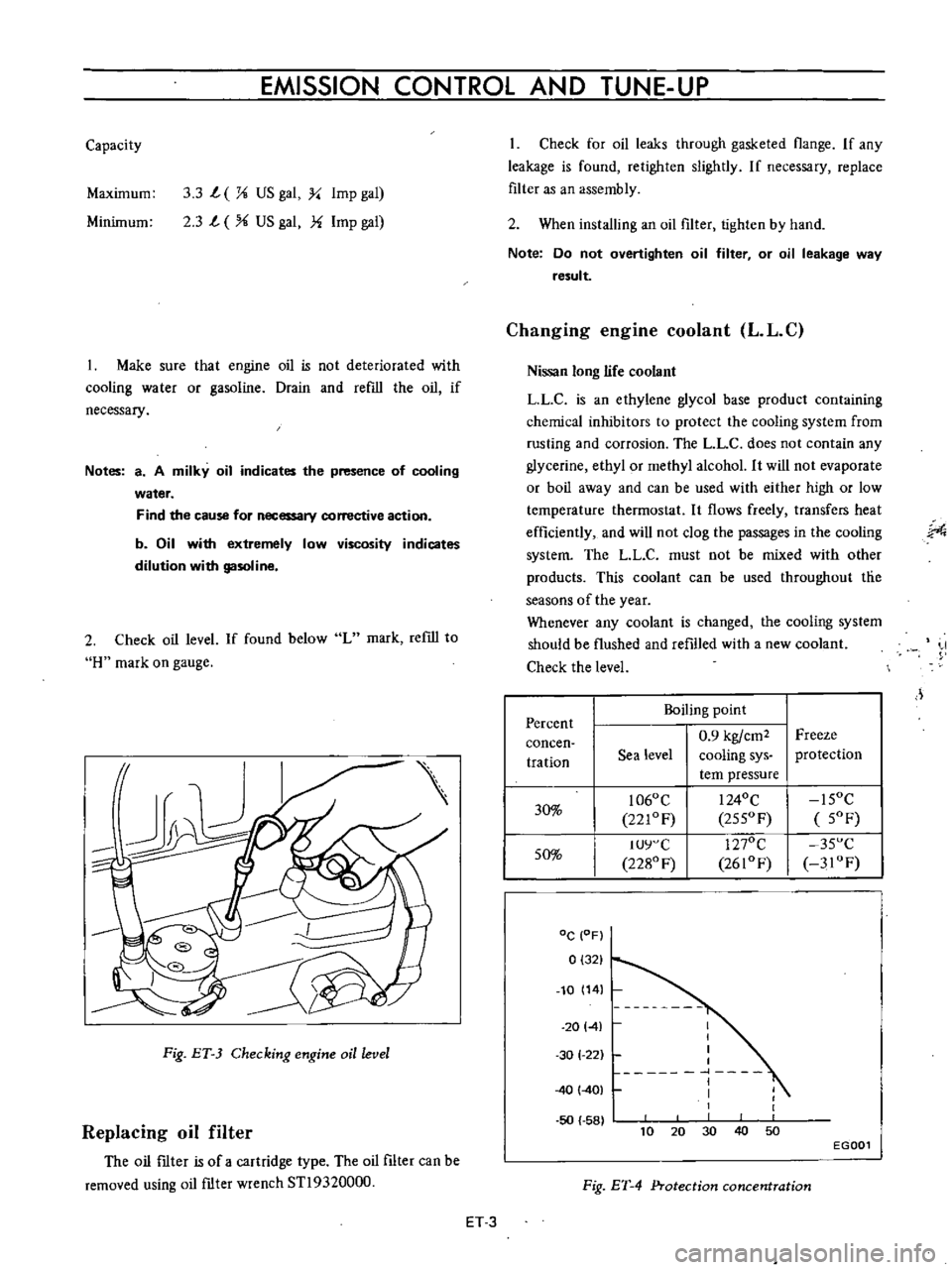
2
Check
oil
level
If
found
below
L
mark
refill
to
H
mark
on
gauge
Fig
ET
3
Checking
engine
oil
level
Replacing
oil
filter
The
oil
ftIter
is
of
a
cartridge
type
The
oil
filter
can
be
removed
using
oil
ftIter
wrench
STl9320000
Check
for
oil
leaks
through
gasketed
flange
If
any
leakage
is
found
retighten
slightly
If
necessary
replace
filter
as
an
assembly
2
When
installing
an
oil
filter
tighten
by
hand
Note
Do
not
overtighten
oil
filter
or
oil
leakage
way
result
Changing
engine
coolant
L
L
C
Nissan
long
life
coolant
LLC
is
an
ethylene
glycol
base
product
containing
chemical
inhibitors
to
protect
the
cooling
system
from
rusting
and
corrosion
The
L
L
C
does
not
contain
any
glycerine
ethyl
or
methyl
alcohol
It
will
not
evaporate
or
boil
away
and
can
be
used
with
either
high
or
low
temperature
thermostat
It
flows
freely
transfers
heat
efficiently
and
will
not
clog
the
passages
in
the
cooling
system
The
LL
C
must
not
be
mixed
with
other
products
This
coolant
can
be
used
throughout
tlie
seasons
of
the
year
Whenever
any
coolant
is
changed
the
cooling
system
should
be
flushed
and
refilled
with
a
new
coolant
Check
the
level
J
Percent
Boiling
point
0
9
kgfcm2
Freeze
concen
tration
Sea
level
cooling
sys
protection
tern
pressure
30
1060
C
I
240C
15OC
221OF
255OF
5OF
50
IUY
C
1270C
35
C
2280
F
2610F
3IOF
DC
OF
0
321
10
14
20141
50
58
I
I
I
I
1
I
I
1
30
1
22
40
401
40
10
30
50
20
EGOOl
Fig
ET
4
Protection
concentration
ET
3
Page 309 of 513

ENGINE
Checking
cooling
system
hoses
and
connections
Check
cooling
system
hoses
and
fiHings
for
loose
connections
and
deterioration
Retighten
or
replace
as
necessary
Inspection
of
radiator
cap
Apply
reference
pressure
0
9
kg
cm1
13
psi
to
radiator
cap
by
means
of
a
cap
tester
to
see
if
it
is
in
good
condition
Replace
cap
assembly
if
necessary
ET012
Fig
ET
5
Testing
radiator
cap
Cooling
system
pressure
test
With
radiator
cap
removed
apply
reference
pressure
1
6
kg
cm1
23
psi
to
the
cooling
system
bv
means
of
a
tester
to
check
for
leaks
at
the
system
compo
nents
Water
capacity
with
heater
4
9
l
I
Y
US
gal
l
i
Imp
gal
without
heater
4
2
l
I
i
US
gal
i
Imp
gal
Fig
ET
6
Testing
cooling
system
pressure
Checking
vaccum
fittings
hoses
and
connections
Check
vacuum
system
fittings
and
hoses
for
loose
connections
and
deterioration
Retighten
if
necessary
replace
any
deteriorated
parts
Checking
engine
compression
Compression
pressure
test
Note
To
test
cylinder
compression
remove
all
spark
plugs
and
hold
tester
fitting
tightly
in
spark
plug
hole
of
cylinder
The
tester
is
used
to
determine
whether
cylinder
can
hold
compression
or
whether
there
is
excessive
leakage
past
rings
etc
I
Td10
l
y
Fig
ET
7
Testing
compression
pressure
Test
compression
with
engine
warm
all
spark
plugs
removed
and
throttle
and
choke
valve
opened
No
cylinder
compression
should
be
less
than
80
of
highest
cylinder
s
Excessive
variation
between
cyl
inders
accompanied
by
low
speed
missing
of
the
cylinder
usually
indicates
a
valve
not
properly
seating
or
a
broken
piston
ring
Low
pressures
even
though
uniform
may
indicate
worn
rings
This
may
be
accompanied
by
excessive
oil
consumption
Test
conclusion
If
one
or
more
cylinders
read
low
inject
about
one
tablespoon
of
enigne
oil
on
top
of
the
pistons
in
low
ET
4
Page 327 of 513
ENGINE
6
Start
the
engine
and
continue
idling
as
described
under
paragraphs
I
2
and
3
above
When
several
minutes
have
passed
and
the
valve
is
partially
opened
read
the
thermister
indication
It
is
correct
if
the
reading
falls
between
380C
1000
F
and
550C
1300
F
If
the
reading
is
abnormal
replace
the
sensor
7
On
the
engine
equipped
with
an
idle
compensator
as
service
option
do
as
follows
before
replacing
the
sensor
Clog
hose
on
idle
compensator
side
by
twisting
or
clamping
it
and
check
the
temperature
as
given
in
paragraphs
5
and
6
above
If
the
thermometer
shO
vs
correct
temperature
replace
the
idle
compensa
tOf
if
the
reading
is
abnormal
replace
the
sensor
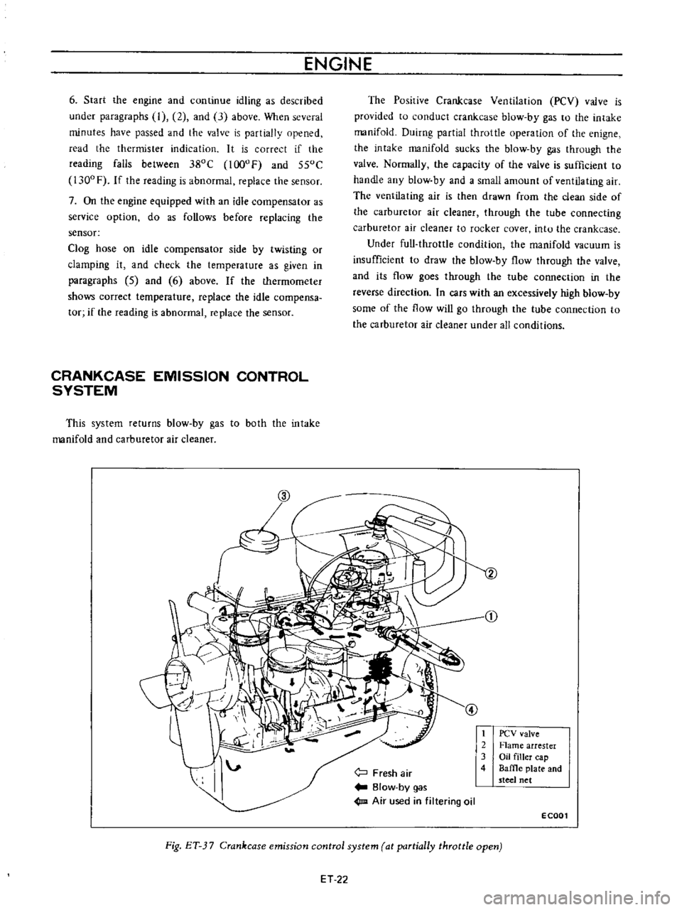
CRANKCASE
EMISSION
CONTROL
SYSTEM
This
system
returns
blow
by
gas
to
both
the
intake
manifold
and
carburetor
air
cleaner
The
Posirive
Crankcase
Ventilation
PCV
valve
is
provided
to
conduct
crankcase
blow
by
gas
to
the
intake
manifold
Duirng
partial
throttle
operation
of
the
enigne
the
intake
manifold
sucks
the
blow
by
gas
through
the
valve
Normally
the
capacity
of
the
valve
is
sufficient
to
handle
any
blow
by
and
a
small
amount
of
ventilating
air
The
ventilating
air
is
then
drawn
from
the
clean
side
of
the
carburetor
air
cleaner
through
the
tube
connecting
carburetor
air
cleaner
to
rocker
cover
intu
the
crankcase
Under
full
throttle
condition
the
manifold
vacuum
is
insufficient
to
draw
the
blow
by
flow
through
the
valve
and
its
flow
goes
through
the
tube
connection
in
the
reverse
direction
In
cars
with
an
excessively
high
blow
by
some
of
the
flow
will
go
through
the
tube
connection
to
the
carburetor
air
cleaner
under
all
conditions
j
Fresh
air
Blow
by
gas
1m
Air
used
in
filtering
oil
t
2
3
4
PCV
valve
Flame
arrester
Oil
filler
cap
Baffle
plate
and
steel
net
ECOOl
Fig
ET
3
7
Crankcase
emission
control
system
at
partially
throttle
open
ET
22
Page 330 of 513
EMISSION
CONTROL
AND
TUNE
UP
SERVICE
DATA
AND
SPECIFICATIONS
Valve
clearance
Hot
Intake
Exhaust
mm
in
rom
in
rom
in
kg
lb
0
35
0
014
0
35
0
014
10
to
15
0
394
to
0
591
10
22
Fan
belt
tension
Tightening
torque
Cold
Cylinder
head
bolts
kg
m
ft
lb
1st
turn
2nd
turn
Re
tightening
torque
Hot
Manifold
nuts
Carburetor
nuts
4
0
to
4
5
29
to
33
5
5
to
6
0
40
to
43
6
0
to
6
5
43
to
47
0
9
to
I
4
6
5
to
10
0
5
to
1
0
3
6
to
7
2
1
5
to
2
0
II
to
14
Spark
plugs
Oil
capacity
of
engine
including
oil
ftIter
Maximum
L
US
gal
Imp
gal
L
US
gal
Imp
gal
3
3
U
14
2
3
Ii
Minimum
Water
capacity
of
cooling
system
Without
heater
L
US
gal
Imp
gal
With
heater
L
US
gal
Imp
gal
4
2
1
U
4
9
I
4
11
12
5
to
14
5
I78
to
206
350
Compression
pressure
at
rpm
kg
em
psi
Battery
specific
gravity
Permissible
value
Fully
charged
value
at
200C
680F
Frigid
climates
Tropical
climates
Other
elima
tes
Over
1
22
Over
1
18
Over
1
20
1
28
1
23
1
26
Ignition
timing
degree
Distributor
50
B
T
D
C
Condenser
capacity
mm
in
degrees
IlF
Micro
Farad
0
45
to
0
55
0
018
to
0
022
49
to
55
0
22
5
Point
gap
Dwell
angle
Condenser
insulation
resistance
Mil
Mega
ohms
ET
25
Page 342 of 513
ENGINE
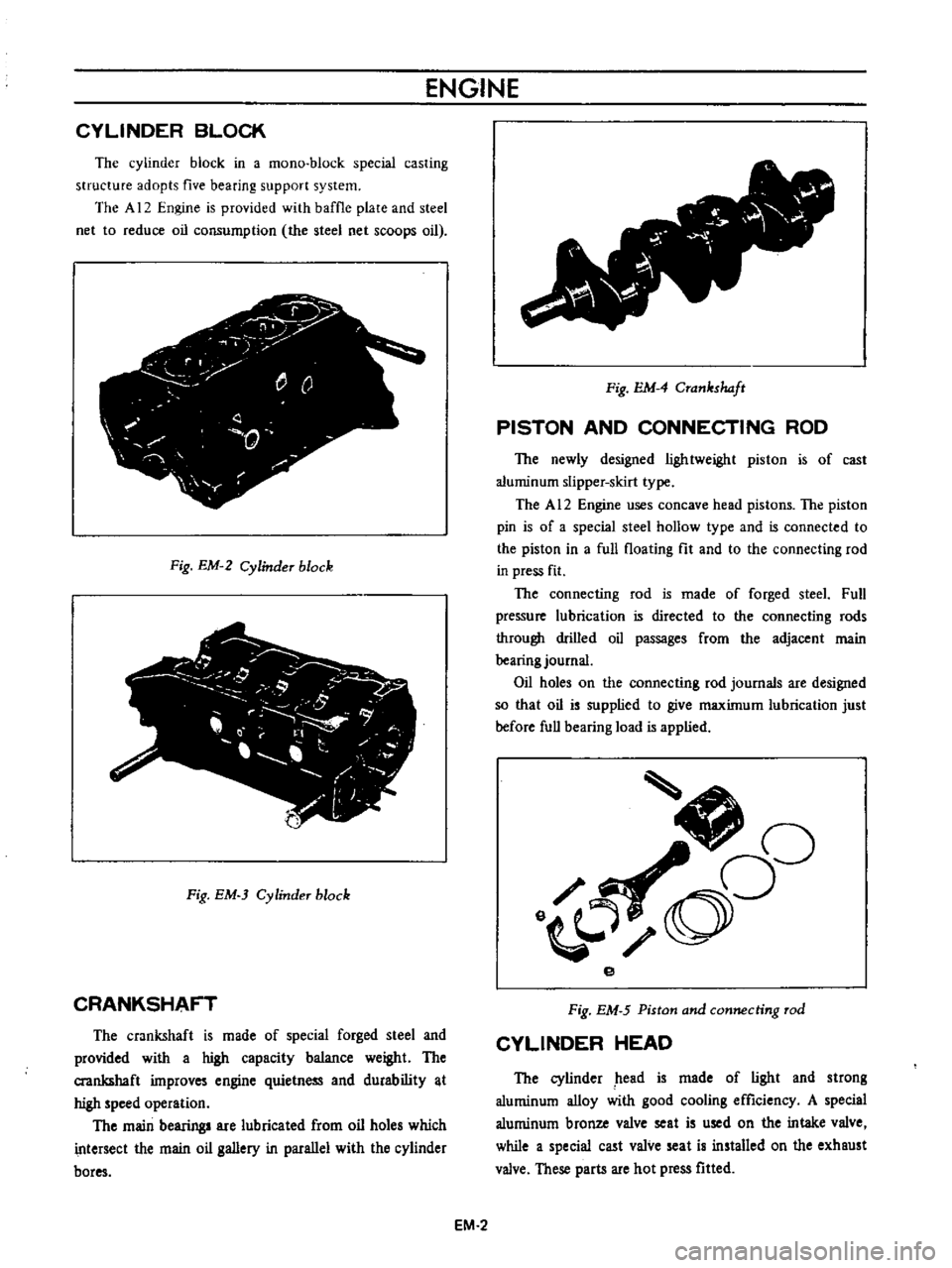
CYLINDER
BLOCK
The
cylinder
block
in
a
mono
block
special
casting
structure
adopts
five
bearing
support
system
The
A
12
Engine
is
provided
with
baffle
plate
and
steel
net
to
reduce
oil
consumption
the
steel
net
scoops
oil
j
y
r
0
Q
0
T
Fig
EM
2
Cylinder
block
Fig
EM
3
Cylinder
block
CRANKSHAFT
The
crankshaft
is
made
of
special
forged
steel
and
provided
with
a
high
capacity
balance
weight
The
crankshaft
improves
engine
quietness
and
durability
t
high
speed
operation
The
main
bearing
are
lubricated
from
oil
holes
which
intersect
the
main
oil
gallery
in
parallel
with
the
cylinder
bores
v
Fig
EM
4
Crankshaft
PISTON
AND
CONNECTING
ROD
The
newly
designed
lightweight
piston
is
of
cast
aluminum
slipper
skirt
type
The
A
12
Engine
uses
concave
head
pistons
The
piston
pin
is
of
a
special
steel
hollow
type
and
is
connected
to
the
piston
in
a
full
floating
fit
and
to
the
connecting
rod
in
press
fit
The
connecting
rod
is
made
of
forged
steeL
Full
pressure
lubrication
is
directed
to
the
connecting
rods
through
drilled
oil
passages
from
the
adjacent
main
bearing
journal
Oil
holes
on
the
connecting
rod
journals
are
designed
so
that
oil
is
supplied
to
give
maximum
lubrication
just
before
full
bearing
load
is
applied
J
oO
o
e
Fig
EM
5
Piston
and
connecting
rod
CYLINDER
HEAD
The
cylinder
head
is
made
of
light
and
strong
aluminum
alloy
with
good
cooling
efficiency
A
special
aluminum
bronze
valve
seat
is
used
on
the
intake
valve
while
a
special
cast
valve
seat
is
installed
on
the
exhaust
valve
These
parts
are
hot
press
fitted
EM
2
Page 451 of 513
ENGINE
ElECTRICAL
SYSTEM
CHECKING
AND
ADJUSTMENT
Cap
and
rotor
head
Cap
and
rotor
head
must
always
be
kept
clean
to
maintain
good
insulation
durability
since
high
tension
voltage
from
ignition
coil
is
imposed
on
them
Sometimes
inside
of
the
cap
and
rotor
head
is
covered
with
fine
carbon
particles
and
dust
Whenever
crack
or
trace
of
leakage
is
found
on
the
cap
replace
with
a
new
one
Recommend
the
rotor
head
also
be
replaced
with
a
new
one
if
excessively
damaged
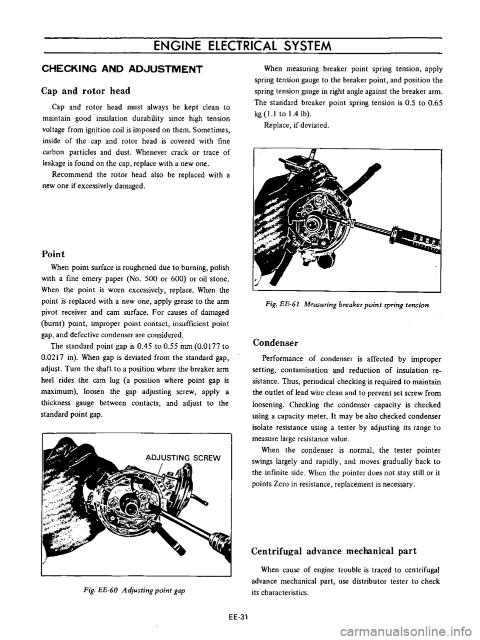
Point
When
point
surface
is
roughened
due
to
burning
polish
with
a
fine
emery
paper
No
500
or
600
or
oil
stone
When
the
point
is
worn
excessively
replace
When
the
point
is
replaced
with
a
new
one
apply
grease
to
the
arm
pivot
receiver
and
earn
surface
For
causes
of
damaged
burnt
point
improper
point
contact
insufficient
point
gap
and
defective
condenser
are
considered
The
standard
point
gap
is
0
45
to
0
55
mm
0
0177
to
0
0217
in
When
gap
is
deviated
from
the
standard
gap
adjust
Turn
the
shaft
to
a
position
where
the
breaker
arm
heel
rides
the
com
lug
a
position
where
point
gap
is
maximum
loosen
the
gap
adjusting
screw
apply
a
thickness
gauge
between
contacts
and
adjust
to
the
standard
point
gap
Fig
EE
60
Adjusting
point
gap
When
measuring
breaker
point
spring
tension
apply
spring
tension
gauge
to
the
breaker
point
and
position
the
spring
tension
gauge
in
right
angle
against
the
breaker
arm
The
standard
breaker
point
spring
tension
is
0
5
to
0
65
kg
1
1
to
I
4Ib
Replace
if
deviated
Fig
EE
61
Measuring
breaker
point
spring
tension
Condenser
Performance
of
condenser
is
affected
by
improper
setting
contamination
and
reduction
of
insulation
re
sistance
Thus
periodical
checking
is
required
to
maintain
the
outlet
of
lead
wire
clean
and
to
prevent
set
screw
from
loosening
Checking
the
condenser
capacity
is
checked
using
a
capacity
meter
It
may
be
also
checked
condenser
isolate
resistance
using
a
tester
by
adjusting
its
range
to
measure
large
resistance
value
When
the
condenser
is
normal
the
tester
pointer
swings
largely
and
rapidly
and
moves
gradually
back
to
the
infinite
side
When
the
pointer
does
not
stay
still
or
it
points
Zero
in
resistance
replacement
is
necessary
Centrifugal
advance
mechanical
part
When
cause
of
engine
trouble
is
traced
to
centrifugal
advance
mechanical
part
use
distributor
tester
to
check
its
characteristics
EE
31
Page 507 of 513
CHASSIS
SERVICE
DATA
AND
SPECIFICATIONS
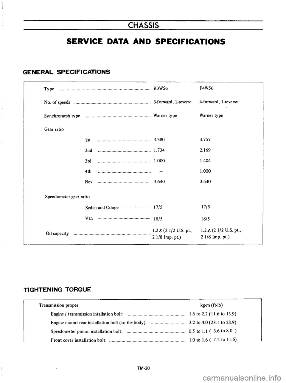
GENERAL
SPECIFICATIONS
Type
No
of
speeds
Synchromesh
type
Gear
ratio
1st
2nd
3rd
4th
Rev
Speedometer
gear
ratio
Sedan
and
Coupe
Van
Oil
capacity
TIGHTENING
TORQUE
Transmission
proper
Engine
transmission
intallation
bolt
Engine
mount
rear
installation
bolt
to
the
body
Speedometer
pinion
installation
bolt
Front
cover
installation
bolt
TM
20
R3W56
F4W56
3
forward
I
reverse
4
forward
I
reverse
Warner
type
Warner
type
3
380
3
757
1734
2
169
1
000
1404
1
000
3
640
3
640
17
5
17
5
18
5
18
5
1
2
L
2
1
2
U
S
pt
2
1
8
Imp
pt
1
2
L
2
1
2
U
S
pt
21
8
Imp
pt
kg
m
ft
Ib
1
6
to
2
2
11
6
to
15
9
3
2
to
4
0
23
1
to
28
9
0
5
to
1
1
3
6
to
8
0
1
0
to
1
6
7
2
to
11
6