1973 DATSUN B110 instrument panel
[x] Cancel search: instrument panelPage 261 of 513

The
lamp
does
not
go
out
when
the
engine
is
started
Faulty
charging
system
BODY
Inspect
the
charging
system
WINDSHIELD
WIPER
AND
WASHER
Description
Wiper
motor
replacement
Wiper
blade
operating
range
CONTENTS
BE
26
BE
27
BE
27
Description
The
windshield
wipers
consist
of
wiper
motor
link
mechanism
wiper
arms
and
blades
The
wiper
motor
unit
consists
of
a
motor
and
auto
stop
mechanism
The
wiper
rnotor
is
of
a
2
speed
type
When
the
wiper
switch
knob
is
pulled
to
the
I
st
step
the
windshield
wipers
operate
at
low
speed
and
when
pulled
to
the
2nd
step
operate
at
high
speed
The
wiper
motor
unit
is
located
on
the
cowl
dash
in
BATTERY
Cl
WIPER
MOTOR
rrQ
J
WASHER
MOTOR
IB
ILRI
L
CJ
LA
t
Y
I
Ll
j
IBI
1
f
I
LW
I
Wiper
washer
switch
replacement
Washer
nozzle
adjustment
TROUBLE
OIAGNOSES
ANO
CORRECTIONS
BE
27
BE
27
BE
28
the
engine
compartment
and
the
link
mechanism
is
located
behind
the
instrument
panel
The
electrically
operated
windshield
washer
consists
of
washing
fluid
lank
with
rnotor
and
pump
washer
nozzles
and
vinyl
tube
used
to
connect
those
compo
nents
The
windshield
washer
switch
is
combined
with
the
windshield
wiper
switch
to
a
single
unit
When
operating
the
washer
twist
the
switch
knob
IG
FUSE
W
v
l
i
f
WIPER
SWITCH
10FFI
I
2
I
TWIST
I
y
ILl
I
b
I
J
6
I
BLII
Fig
BE
43
Circuit
diagram
for
windshield
wiper
washer
system
BE
26
Page 264 of 513

BODY
ELECTRICAL
Improper
stop
position
of
wiper
arm
Improperly
positioned
blade
and
arm
Correct
position
Damaged
or
worn
auto
stop
point
Replace
motor
Improper
wiping
Worn
rubber
blade
Replace
blade
Inadequate
pressing
force
of
wiper
arm
Replace
wiper
arm
IGNITION
SWITCH
AND
STEERING
LOCK
CONTENTS
IGNITION
SWITCH
Removal
IGNITION
SWITCH
WITH
STEER
ING
LOCK
BE
29
BE
29
BE
29
IGNITION
SWITCH
This
3
or
4
position
switch
is
installed
on
the
ignition
switch
bracket
which
is
installed
on
the
instrument
panel
with
two
screws
and
controls
the
engine
ignition
system
and
most
of
electrical
equipment
Removal
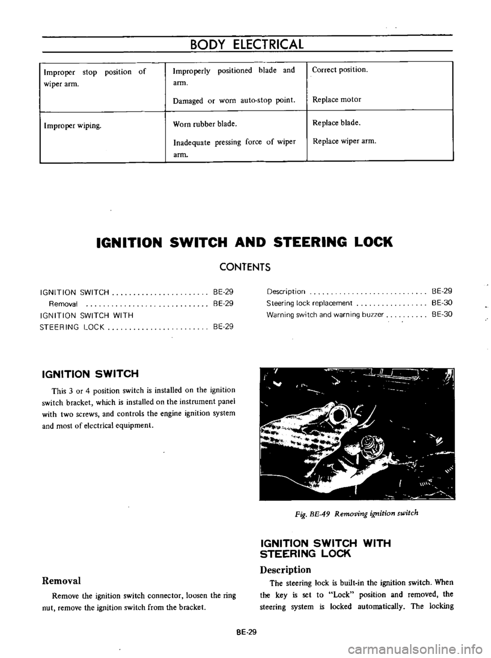
Remove
the
ignition
switch
connector
loosen
the
ring
nut
remove
the
ignition
switch
from
the
bracket
Description
Steering
lock
replacement
Warning
switch
and
warning
buzzer
BE
29
BE
30
BE
30
Fig
BE
49
Removing
ignition
switch
IGNITION
SWITCH
WITH
STEERING
LOCK
Description
The
steering
lock
is
built
in
the
ignition
switch
When
the
key
is
set
to
Lock
position
and
rernoved
the
steering
system
is
locked
automatically
The
locking
8E
29
Page 265 of 513

mechanism
is
installed
on
the
steering
jacket
tube
When
the
key
is
set
to
Lock
position
and
removed
the
steering
lock
spindle
is
inserted
in
a
notch
in
the
collar
which
is
stationarity
set
on
the
steering
shaft
to
lock
the
steering
wheel
The
ignitiun
switch
is
installed
on
the
back
of
key
cylinder
with
a
attaching
screw
and
interchangeable
tf
iY
t
7
a
1
Ignition
switch
part
2
Key
cylinder
part
3
Steering
jacket
tube
4
Lock
collar
5
Lock
pindle
6
Steering
shaft
7
Self
shear
type
screw
8
Attaching
screw
Fig
BE
50
Steering
lock
Key
position
Terminal
OFFor
GARAGE
Lock
ON
ST
ART
B
Battery
IG
Ignition
S
Starter
R
Resistance
b
1
Steering
lock
replacement
For
the
purpuse
of
tamper
proof
the
self
shear
type
screws
are
used
and
their
heads
are
sheared
off
when
installed
so
that
the
steering
lock
system
cannot
be
removed
easily
Replace
the
steering
lock
proper
in
accordance
with
the
following
instructions
when
required
Loosen
two
attaching
screws
and
break
the
remaining
twu
self
shear
type
screws
with
a
drill
or
other
proper
tool
Now
remove
the
steering
lock
proper
from
the
BODY
BE
30
steering
jacket
tube
When
installing
a
new
steering
lock
proper
be
sure
tu
tighten
two
new
self
shear
type
screws
to
shear
off
their
heads
Warning
switch
and
warnmg
buzzer
Fig
BE
51
Warning
switch
The
circuit
of
this
warning
system
is
closed
when
the
door
is
opened
with
the
steering
unlocked
because
the
door
switch
and
warning
switch
are
connected
in
series
When
the
cicuit
is
closed
the
buzzer
sounds
When
replacing
the
warning
switch
disconnect
two
cables
remove
the
cap
loosen
two
attaching
screws
and
remove
the
warning
switch
The
warning
buzzer
is
installed
on
the
back
left
side
of
the
instrument
panel
with
two
attaching
screws
FUSE
WARNING
SWITCH
WARN
BUZZ
G
n
WITCH
t
Fig
BE
52
Circuit
diagram
for
warning
system
Page 266 of 513

BODY
ELECTRICAL
CLOCK
Installation
upper
portion
of
the
instrument
panel
Connect
red
blue
cable
or
red
green
cable
for
illumi
nation
lamp
of
the
clock
to
the
terminals
on
the
printed
circuit
board
for
illumination
lamp
on
the
meter
housing
Ground
the
clock
ground
cable
In
the
case
of
a
square
type
clock
tighten
the
ground
cable
together
with
the
meter
housing
installation
screw
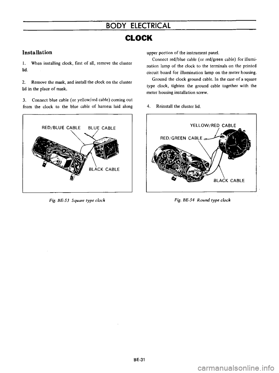
1
When
installing
clock
first
of
all
remove
the
cluster
lid
2
Remove
the
mask
and
install
the
clock
on
the
cluster
lid
in
the
place
of
mask
3
Connect
blue
cable
or
yellow
red
cable
coming
out
from
the
clock
to
the
blue
cable
of
harness
laid
along
4
Reinstall
the
cluster
lid
RED
BLUE
CABLE
BLUE
CABLE
Fig
BE
53
Square
type
clock
Fig
BE
54
Round
type
clock
BE
31
Page 267 of 513

BODY
RADIO
Removal
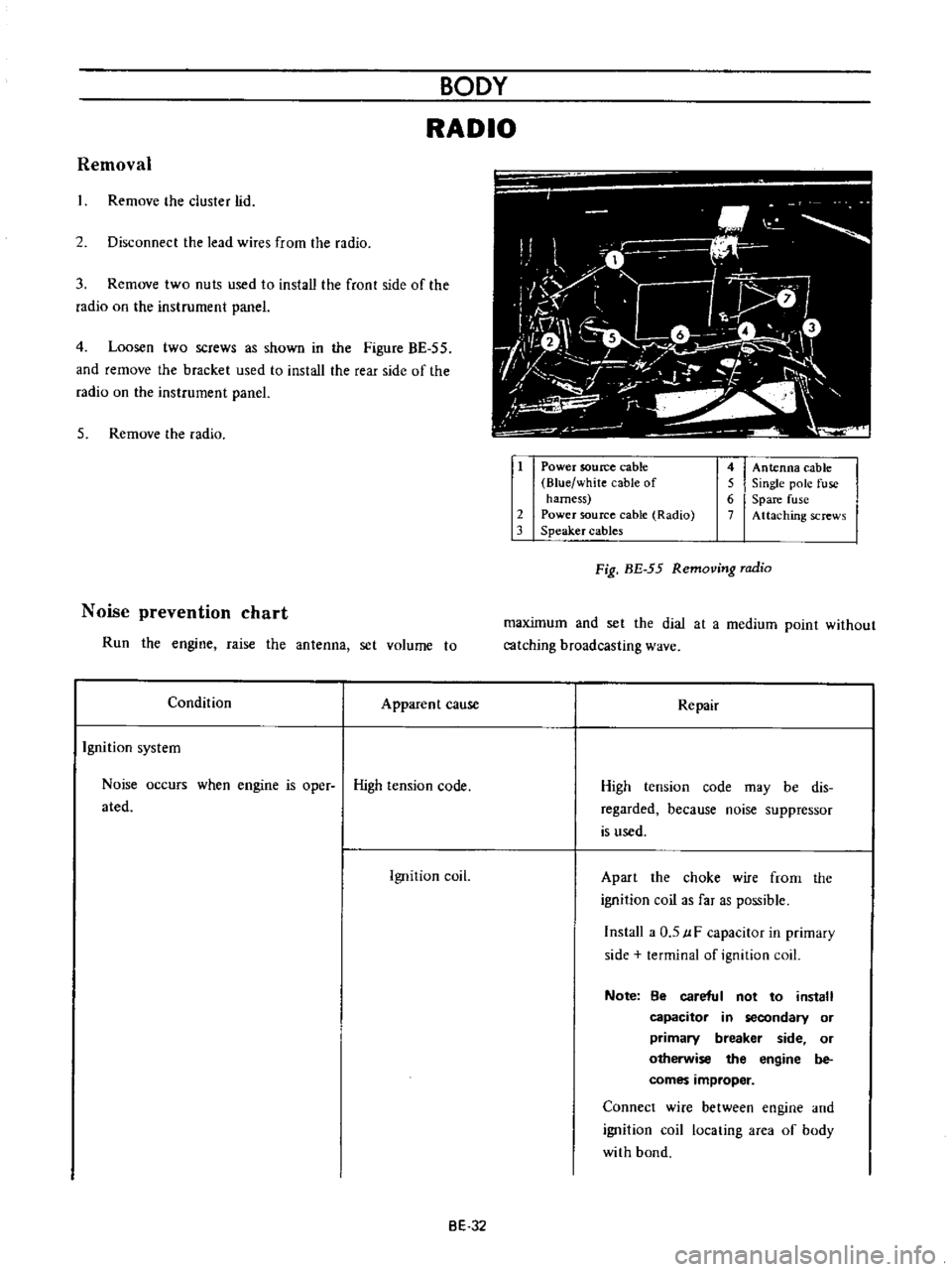
Remove
he
cluster
lid
2
Disconnect
the
lead
wires
from
the
radio
3
Remove
two
nuts
used
to
install
the
front
side
of
the
radio
on
the
instrument
panel
4
Loosen
two
screws
as
shown
in
the
Figure
BE
55
and
remove
the
bracket
used
to
install
the
rear
side
of
the
radio
on
the
instrument
panel
5
Remove
the
radio
Noise
prevention
chart
Run
the
engine
raise
the
antenna
set
volume
to
Condition
Apparent
cause
Ignition
system
Noise
occurs
when
engine
is
oper
High
tension
code
ated
Ignition
coil
i
O
i
M
1
iiJ
1
7
L
l
o
f
I
ft
V
r
1
1
v
I
I
t
i
J
iL
1
Power
soutee
cable
Blue
white
cable
of
harness
2
Power
source
cable
Radio
3
Speaker
cables
4
Antenna
cable
5
Single
pole
fuse
6
Spare
fuse
7
Attaching
screws
Fig
BE
55
Removing
radio
maximum
and
set
the
dial
at
a
medium
point
without
catching
broadcasting
wave
Repair
High
tension
code
may
be
dis
regarded
because
noise
suppressor
is
used
Apart
the
choke
wire
frorn
the
ignition
coil
as
far
as
possible
Install
a
0
5
uF
capacitor
in
primary
side
terminal
of
ignition
coil
Note
8e
careful
not
to
install
capacitor
in
secondary
or
primary
breaker
side
or
otherwise
the
engine
be
comes
improper
Connect
wire
between
engine
and
ignition
coil
locating
area
of
body
with
bond
BE
32
Page 270 of 513

BODY
ELECTRICAL
heater
unit
on
the
dash
board
and
remove
the
heater
unit
carefully
panel
8
Rernove
two
self
tapping
screws
from
back
of
the
instrument
panel
and
remove
the
defroster
nozzle
7
When
removing
the
heater
control
from
the
instru
ment
panel
remove
the
control
knob
and
loosen
two
screws
used
to
install
the
heater
control
on
the
instrument
9
The
heater
unit
is
installed
in
reverse
sequence
of
removal
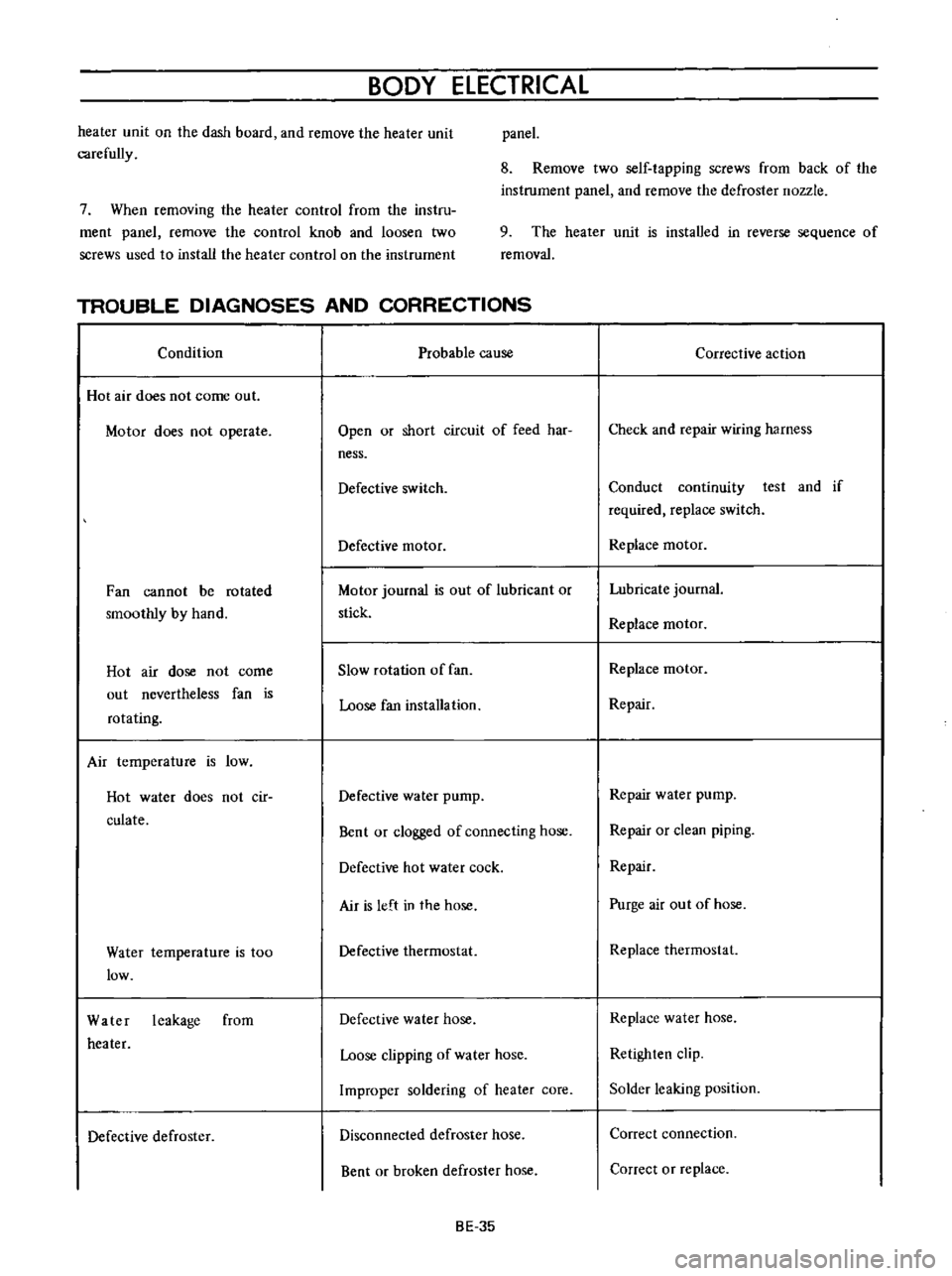
TROUBLE
DIAGNOSES
AND
CORRECTIONS
Condition
Probable
cause
Hot
air
does
not
come
out
Motor
does
not
operate
Open
or
short
circuit
of
feed
har
ness
Defective
switch
Defective
motor
Fan
cannot
be
rotated
smoothly
by
hand
Motor
journal
is
out
of
lubricant
or
stick
Hot
air
dose
not
come
out
nevertheless
fan
is
rotating
Slow
rotation
of
fan
Loose
fan
installation
Air
temperature
is
low
Hot
water
does
not
cir
culate
Defective
water
pump
Bent
or
clogged
of
connecting
hose
Defective
hot
water
cock
Air
is
left
in
the
hose
Water
temperature
is
too
low
Defective
thermostat
Water
leakage
from
heater
Defective
water
hose
Loose
clipping
of
water
hose
Improper
soldering
of
heater
core
Defective
defroster
Disconnected
defroster
hose
Bent
or
broken
defroster
hose
BE
35
Corrective
action
Check
and
repair
wiring
harness
Conduct
continuity
test
and
if
required
replace
switch
Replace
motor
Lubricate
journal
Replace
motor
Replace
motor
Repair
Repair
water
pump
Repair
or
clean
piping
Repair
Purge
air
out
of
hose
Replace
thermostat
Replace
water
hose
Retighten
clip
Solder
leaking
position
Correct
connection
Correct
or
replace