1969 DATSUN B110 ECU
[x] Cancel search: ECUPage 66 of 136
Brakes
DIsassembly
Remove
mud
and
other
contamInations
from
the
caLiper
as
embly
before
dlsa
sembly
DraIn
bl
ake
fluId
flOm
the
wheel
cylinder
Loosen
the
aIr
bleeder
and
depres
the
pistons
A
and
B
Into
the
cylInder
See
FIg
125
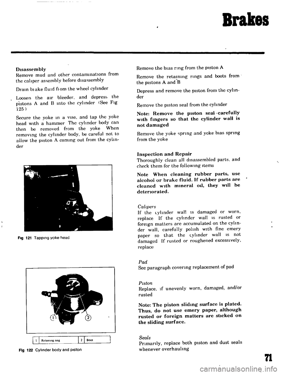
Secure
the
yoke
In
a
vIse
and
tap
the
yoke
head
with
a
hammer
The
cylinder
body
can
then
be
removed
from
the
yoke
When
remOVIng
the
cylinder
body
be
careful
not
to
allow
the
piston
A
comIng
out
from
the
cylIn
der
FIg
121
TapPing
yoke
head
5
I
B
Q
Retamlng
nng
J
Boot
Fig
122
Cylinder
body
and
piston
Remove
the
bIas
nng
from
the
piston
A
Remove
the
retaInIng
nngs
and
boots
from
the
pistons
A
and
B
Depress
and
remove
the
piston
from
the
cylin
der
Remove
the
piston
seal
from
the
cylinder
Note
Remove
the
p1ston
seal
carefully
w1th
fmgers
so
that
the
cylinder
wall
is
not
damaged
Remove
the
yoke
prIng
and
yoke
bias
sprIng
from
the
yoke
Inspection
and
Repair
Thoroughly
clean
all
dIsassembled
parts
and
check
them
for
the
follOWIng
Items
Note
When
cleaning
rubber
parts
use
alcohol
or
brake
fluid
If
rubber
parts
are
cleaned
wIth
mmeral
Oil
they
will
be
detenorated
Calzpers
If
the
cylInder
wall
IS
damaged
or
worn
replace
If
the
cylinder
wall
IS
rusted
or
foreIgn
matters
are
accumulated
on
the
cylIn
der
wall
carefully
polIsh
wIth
fine
emery
paper
so
that
the
cylInder
wall
IS
not
damaged
If
rusted
or
roughened
excessively
replace
Pad
See
paragraph
covenng
replacement
of
pad
PIston
Replace
If
unevenly
worn
damaged
and
or
rusted
Note
The
piston
slidmg
surface
is
plated
Thus
do
not
use
emery
paper
although
rusted
or
foreign
matters
are
sttcked
on
the
sliding
surface
Seals
Prlmanly
replace
both
pIston
and
dust
seals
whenever
overhauling
n
Page 74 of 136
Brakes
Adjusting
shIm
thickness
for
selectIOn
o
0197
In
00315
In
o
0630
In
Note
When
adjusting
be
sure
to
use
ad
Jusbng
sh1ms
having
same
th1ckness
for
upper
and
lower
brake
master
cylinder
IOstallahon
bolts
Upon
completIOn
of
adjusting
shIm
adjust
ment
tighten
the
stopper
down
to
such
an
ex
tent
that
heIght
of
the
pedal
head
IS
5
57
pO
0787
In
and
tighten
the
lock
nut
becurely
Free
travel
of
the
brake
pedal
IS
0
197
to
0591
tn
and
the
stroke
IS
4
72
In
Hand
Brake
Turn
the
turn
buckle
properly
and
adjust
hand
brake
lever
operatmg
stroke
correctly
so
that
operatmg
stroke
IS
3
091
m
16
notches
at
operatIng
force
of
243
to
331
Ib
Upon
com
pletIOn
of
adjustment
be
sure
to
tIghten
the
lock
nut
Upon
completIOn
of
the
adjustment
release
the
hand
brake
lever
and
make
sure
that
the
rear
wheels
are
not
braked
Normal
btroke
3091
In
6
notches
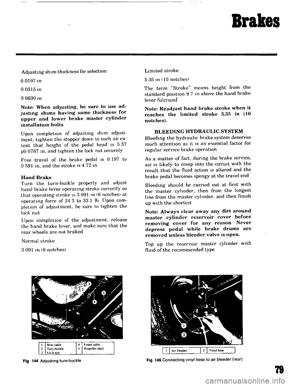
Fig
144
AdJusting
turn
buckle
LImIted
stroke
535
tn
10
notches
The
term
Stroke
means
heIght
from
the
standard
posItIon
8
7
In
above
the
hand
brake
lever
fulcrum
Note
Readjust
hand
brake
stroke
when
it
reaches
the
hmited
stroke
5
35
in
10
notches
BLEEDING
HYDRAULIC
SYSTEM
BleedIng
the
hydrauhc
brake
system
deserves
much
attentIOn
as
It
IS
an
e
senttal
factor
for
regular
servICe
brake
operatIon
As
a
matter
of
fact
durmg
the
brake
serVice
air
IS
lIkely
to
creep
Into
the
CirCUIt
WIth
the
result
that
the
flUId
actIon
IS
altered
and
the
brake
pedal
becomes
spongy
at
the
travel
end
Bleedmg
should
be
carned
out
at
first
WIth
the
master
cylmder
then
from
the
longest
lIne
from
the
master
cylmder
and
then
fimsh
up
With
the
shortest
Note
Always
clear
away
any
dirt
around
master
cylinder
reservoir
cover
before
removing
cover
for
any
reason
Never
depress
pedal
while
brake
drums
are
removed
unless
bleeder
valve
IS
open
Top
up
the
reservOIr
master
cyltnder
With
flUId
of
the
recommended
type
Fig
145
Connecting
Vinyl
hose
to
air
bleeder
rear
79
Page 91 of 136
Clutch
DESCRIPTION
The
clutch
IS
a
sIngle
dry
dIsc
diaphragm
prIng
type
clutch
The
major
components
are
clutch
cover
pressure
plate
diaphragm
sprIng
and
wire
rIngs
The
clutch
diSC
IS
provided
WIth
rIveted
plates
on
both
surfaces
and
cot
bprIngs
arranged
In
a
hnk
The
COIl
prIngs
absOl
b
shock
whIle
engagIng
the
clutch
softemng
and
smoothIng
clutch
engagement
Release
bearIng
sleeve
and
WIthdrawal
lever
dre
used
to
control
clutch
engagement
and
disengagement
Each
part
of
the
clutch
assembly
IS
secured
With
rivets
Therefore
when
a
trouble
IS
un
correctable
replace
the
clutch
assembly
With
a
new
assembly
30
1181
r
I
I
I
I
I
8
1
il
f
0
g
it
l
00
r
O
11
I
N
NN
0
to
lt
lt
ll
l
If
N
O
N
I
I
I
I
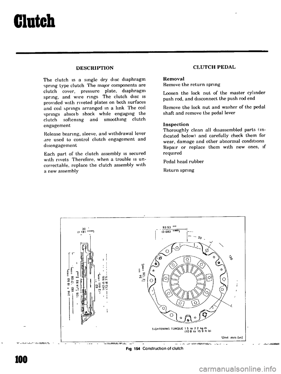
FIg
154
Construction
of
clutch
100
CLUTCH
PEDAL
Removal
Remove
the
return
sprmg
Loosen
the
lock
nut
of
the
master
cyhnder
push
rod
and
disconnect
the
push
rod
end
Remove
the
lock
nut
and
washer
of
the
pedal
shaft
and
remove
the
pedal
lever
Inspection
Thoroughly
clean
all
disassembled
parts
m
dlcated
below
and
carefully
check
them
for
wear
damage
and
other
abnormal
conditions
RepaIr
or
replace
them
With
new
ones
If
reqUIred
Pedal
head
rubber
Return
sprIng
9353
3682
00004
lIGHTENING
TORQUE
1
5
to
2
2
kg
m
108
to
159ft
lbl
UOIt
mm
Inl
Page 93 of 136
Clutch
Pedal
lever
bush
Fulcrum
pedal
pIn
etc
Remstallation
Reinstall
the
clutch
pedal
In
reverse
sequence
of
removal
Adjustment
Adjust
pedal
pad
heIght
to
565
In
Without
stopper
The
adjustment
IS
made
by
selectmg
and
applYIng
shlm
s
haVing
adequate
thIckness
Be
Ule
to
use
shIms
haVIng
same
thIckness
for
both
upper
and
lower
Next
adjust
the
pedal
stopper
properly
so
that
the
pedal
pad
height
IS
557
In
and
secure
the
pOSitIOn
WIth
lock
nut
Note
Make
sure
that
chaSSIS
grease
has
been
applied
to
the
CG
marked
portions
two
places
Grease
if
reqUired
CLUTCH
MASTER
CYLINDER
Removal
DIsconnect
the
push
rod
from
the
cleVIS
DIsconnect
the
clutch
lIne
from
the
master
cylinder
and
draIn
flUid
Remove
the
ecunng
bolts
and
remove
the
master
cyhnder
assembly
from
the
vehIcle
DIsassembly
Remove
the
filler
cap
and
draIn
flUId
Pull
back
the
dust
cover
and
remove
the
snap
rIng
The
stopper
push
rod
pIston
assembly
pnmary
cup
and
return
sptlng
assembly
can
be
removed
Inspection
Thoroughly
clean
all
parts
With
brake
flUId
before
InspectIOn
Check
the
cyhnder
and
piston
for
uneven
wear
or
damage
Replace
If
required
When
clearance
between
the
cylinder
and
pIston
IS
more
than
O
0059
In
replace
the
cyhnder
102
Replace
the
pIston
cup
pnmanly
whenever
the
master
cyhnder
IS
dIsassembled
It
must
also
be
replaced
when
wear
or
deformatIOn
due
to
fatIgue
or
damage
IS
found
Check
the
dust
cover
OIl
reservOIr
filler
cap
and
clutch
lIne
for
damage
or
deformatIOn
If
abnormal
condItIOn
IS
found
replace
With
new
one
Reassembly
Reassemble
the
master
cylInder
assembly
In
reverse
sequence
of
dIsassembly
notIng
the
follOWIng
matters
The
pIston
cup
should
be
soaked
In
brake
flUId
before
reassembly
Install
the
pIston
cup
carefully
so
that
It
IS
correctly
faced
Apply
brake
flUId
suffiCIently
to
the
cyhnder
and
pIston
and
assemble
them
Reinstallation
ReInstall
the
master
cyhnder
assembly
In
reverse
sequence
of
removal
and
adjust
as
follows
Adjust
the
pedal
heIght
by
changmg
the
push
rod
length
Bleed
air
out
of
the
hydrauhc
system
BLEEDING
CLUTCH
SYSTEM
Remove
the
bleed
screw
dust
cap
from
the
operatIng
cyhnder
Open
the
bleed
screw
approximately
three
quarters
of
a
turn
Attach
a
tube
Immer
SIng
the
open
end
mto
a
clean
contaIner
which
contaInS
a
small
amount
of
brake
flUId
Fill
the
master
cyhnder
reservOIr
With
the
recommended
flUId
Depress
the
clutch
pedal
qUIckly
while
keepIng
It
down
retighten
the
bleed
screw
and
allow
It
to
return
slowly
Repeat
thiS
pumpIng
actIOn
unttl
the
flUId
entenng
the
contaIner
IS
free
from
air
bubbles
Screw
up
the
bleed
screw
on
a
down
stroke
of
the
pedal
remove
the
bleec
t1
1
nd
rel1lace
the
dust
cap
Page 104 of 136
Bod
Work
J
G
3
1
7
iJ
0
t
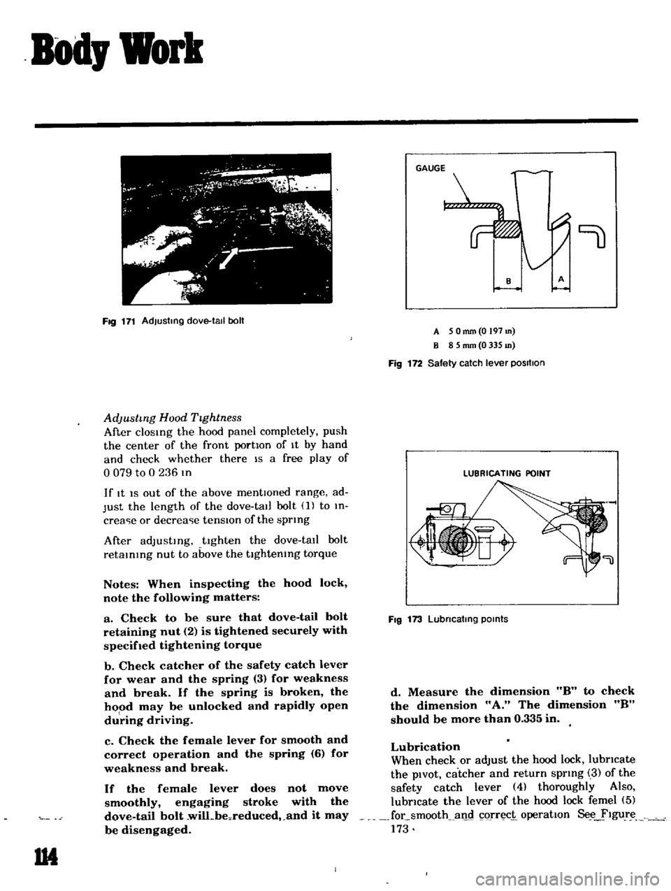
Fig
171
Adjusting
dove
tall
boll
AdJustmg
Hood
TIghtness
After
clOSIng
the
hood
panel
completely
push
the
center
of
the
front
portIon
of
It
by
hand
and
check
whether
there
IS
a
free
play
of
o
079
to
0
236
In
If
It
IS
out
of
the
above
mentIOned
range
ad
Just
the
length
of
the
dove
tall
bolt
1
to
In
crea
ie
or
decrea
ie
tensIOn
of
the
sprIng
After
adJustIng
tighten
the
dove
tall
bolt
retaInIng
nut
to
above
the
tIghtenIng
torque
Notes
When
inspecting
the
hood
lock
note
the
following
matters
a
Check
to
be
sure
that
dove
tail
bolt
retaining
nut
2
is
tightened
securely
with
specifIed
tightening
torque
b
Check
catcher
of
the
safety
catch
lever
for
wear
and
the
spring
3
for
weakness
and
break
If
the
spring
is
broken
the
hood
may
be
unlocked
and
rapidly
open
du
ring
driving
c
Check
the
female
lever
for
smooth
and
correct
operation
and
the
spring
6
for
weakness
and
break
If
the
female
lever
does
not
move
smoothly
engaging
stroke
with
the
dove
tail
bolt
wilLbeoreduced
and
it
may
be
disengaged
1M
9
A
5
Omm
O
197
m
B
8
5
mm
0
335
m
Fig
172
Safety
catch
lever
positIOn
LUBRICATING
POINT
Fig
173
Lubncatlng
POints
d
Measure
the
dimension
8
to
check
the
dimension
A
The
dimension
8
should
be
more
than
0
335
in
Lubrication
When
check
or
adjust
the
hood
lock
lubricate
the
pIvOt
catcher
and
return
sprIng
3
of
the
safety
catch
lever
4
thoroughly
Also
lubricate
the
lever
of
the
hood
lock
femel
5
focsmooth
all
c1
orr
i
operatIon
Se
ylgur
173
Page 106 of 136
Bod
Work
TRUNK
LID
LOCK
Removal
Loosen
m
tallatlOn
bolts
and
remove
the
tl
Iker
and
lock
from
the
body
Remove
the
leaf
chp
lu
ed
to
secure
the
trunk
hd
lock
cylmder
on
the
body
and
remove
the
trunk
lId
lock
cylIndCl
Adjustment
Sedan
When
adjustmg
engagement
between
the
lock
and
tnker
set
the
lock
statlOnanly
and
properly
adjust
stnker
poSitIOn
Adjustmg
stroke
toward
left
and
nght
SIdes
dIrectIOn
IS
0
890
m
and
03150
m
toward
vertical
dIrectIOn
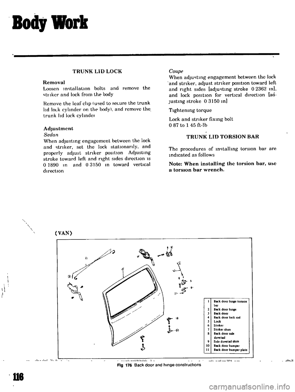
VAN
j
1
II
U8
Coupe
When
adju
tmg
engagement
between
the
lock
and
stnker
adjust
stnker
poSitIOn
toward
left
and
right
Sides
adju
tmg
stroke
02362
m
and
lock
pOSitIOn
for
vertical
directIOn
ad
justmg
stroke
03
50
m
Tlghtemng
torque
Lock
and
stnker
fixmg
bolt
o
87
to
45
ft
lb
TRUNK
LID
TORSION
BAR
The
procedures
of
m
tallIng
torsIOn
bar
are
mdlcated
as
follows
Note
When
installing
the
torsion
bar
u
te
a
torsIOn
bar
wrench
J
tl
l
11
4
i
0
t
b
f
I
Back
door
hUlle
tomon
bOT
2
BlCk
door
hmge
3
Back
door
4
Back
door
lock
rod
l
Lock
6
Stnker
7
Stnker
shun
8
Back
door
side
dovetad
9
Side
dovetl1l
tllm
10
Back
door
bumper
II
Back
door
bumper
plate
Ag
176
Back
door
and
hinge
constructions