1969 DATSUN B110 ECU
[x] Cancel search: ECUPage 8 of 136
ainteDaDee
TUDe
up
VAL
VE
CLEARANCES
Valve
clearance
adjustment
should
be
made
while
engme
IS
stationary
To
adjust
proceed
as
follows
Start
engme
and
run
It
until
It
IS
heated
to
operatIng
temperature
or
at
least
more
than
17S
of
engIne
011
temperature
then
stop
engIne
Rotate
crankshaft
to
bnng
No
1
cylInder
In
top
dead
center
on
ItS
compressIOn
stroke
Remove
valve
rocker
cover
to
gaIn
access
to
valve
operatIng
mechamsm
Adjust
valve
clearance
at
follOWing
four
pOints
while
engIne
IS
still
hot
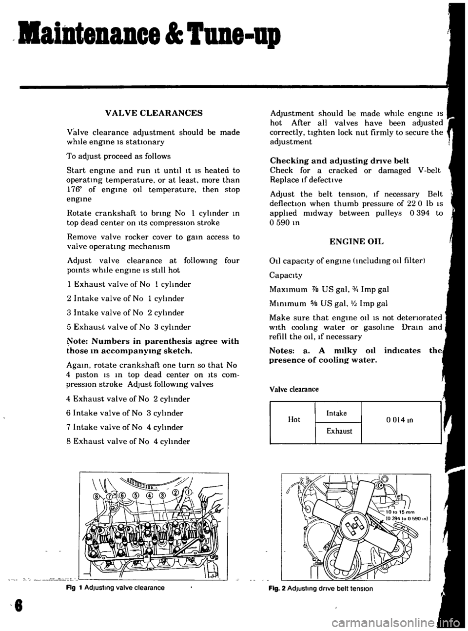
1
Exhaust
valve
of
No
1
cylinder
2
Intake
valve
of
No
1
cylinder
3
Intake
valve
of
No
2
cylinder
5
Exham
t
valve
of
No
3
cylInder
ote
Numbers
in
parenthesis
agree
with
those
10
accompanY1Og
sketch
AgaIn
rotate
crankshaft
one
turn
so
that
No
4
piston
IS
In
top
dead
center
on
ItS
com
pressIOn
stroke
Adjust
follOWIng
valves
4
Exhaust
valve
of
No
2
cylinder
6
Intake
valve
of
No
3
cylinder
7
Intake
valve
of
No
4
cylInder
8
Exhaust
valve
of
No
4
cylinder
Rg
1
AdJustmg
valve
clearance
8
Adjustment
should
ue
made
whIle
engIne
IS
hot
After
all
valves
have
been
adjusted
correctly
tighten
lock
nut
firmly
to
secure
the
adjustment
Checking
and
adjusting
drive
belt
Check
for
a
cracked
or
damaged
V
belt
Replace
If
defective
Adjust
the
belt
tenSIOn
If
necessary
Belt
deflectIOn
when
thumb
pressure
of
220
Ib
IS
applied
midway
between
pulleys
0394
to
o
590
In
ENGINE
OIL
011
capacity
of
engIne
IncludIng
011
filter
Capacity
MaXimum
VB
US
gal
Imp
gal
MInimum
5IB
US
gal
III
Imp
gal
Make
sure
that
engIne
011
IS
not
detenorated
With
cooling
water
or
gasolIne
DraIn
and
refill
the
011
lf
necessary
Notes
a
A
m1lky
011
indlcates
presence
of
cooling
water
Valve
clearance
Hot
Intake
0014
In
Exhaust
Fig
2
AdJustmg
dnve
belt
tension
Page 18 of 136
Bogioe
0
WAI
CI
o
o
WAIl
Cl
I
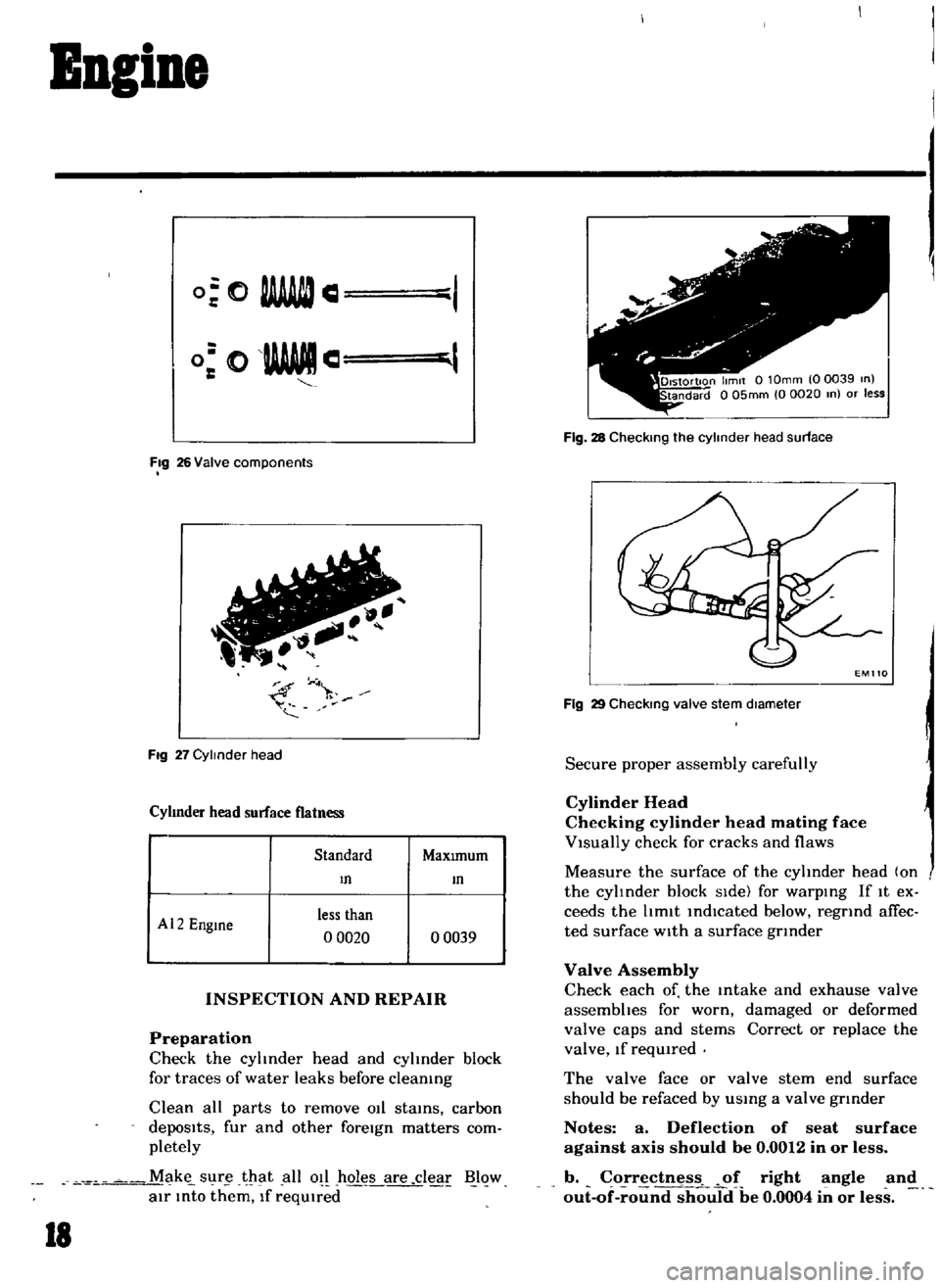
Fig
26
Valve
components
FIg
27
Cylinder
head
Cyhnder
head
surface
flatness
Standard
MaxImum
m
m
Al2
Engme
less
than
o
0020
o
0039
INSPECTION
AND
REPAIR
Preparation
Check
the
cyhnder
head
and
cylinder
block
for
traces
of
water
leaks
before
cleaning
Clean
all
parts
to
remove
011
stains
carbon
depoSits
fur
and
other
foreIgn
matters
com
pletely
M
k
s
lr
1at
all
o
hol
Lare
clear
Blow
air
Into
them
If
reqUIred
18
Fig
28
Checking
the
cylinder
head
surface
Fig
29
CheckIng
valve
stem
dIameter
Secure
proper
assembly
carefully
Cylinder
Head
Checking
cylinder
head
mating
face
VIsually
check
for
cracks
and
flaws
Measure
the
surface
of
the
cyhnder
head
on
the
cyhnder
block
SIde
for
warping
If
It
ex
ceeds
the
hmlt
indIcated
below
regrind
afTec
ted
surface
wIth
a
surface
grinder
Valve
Assembly
Check
each
of
the
Intake
and
exhause
valve
assembhes
for
worn
damaged
or
deformed
valve
caps
and
stems
Correct
or
replace
the
valve
If
reqUIred
The
valve
face
or
valve
stem
end
surface
should
be
refaced
by
usmg
a
valve
gtlnder
Notes
a
Deflection
of
seat
surface
against
axis
should
be
0
0012
in
or
less
b
o
rr
ctnes
f
right
angle
and
out
of
round
should
be
0
0004
in
or
less
Page 27 of 136
Bogine
Note
Set
the
locate
plate
so
as
the
LOWER
mark
comes
to
the
engine
bot
tom
side
Set
the
maIn
bearIngR
on
theIr
posItIOns
on
the
cylinder
block
Notes
a
The
center
bearmg
No
3
bearmg
is
a
flanged
type
for
thrust
force
b
Two
lOner
bearmgs
No
2
and
No
4
are
of
the
same
type
c
The
front
bearmg
No
1
IS
the
same
type
as
the
rear
bearmg
No
5
d
All
bearings
except
for
No
I
bearing
are
interchangeable
between
upper
and
lower
bearings
Apply
engIne
OIl
to
the
mam
bearIng
surfaces
on
both
sIdes
of
the
cyltnder
block
and
cap
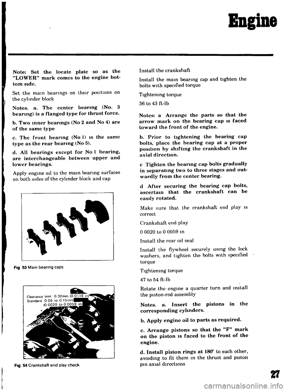
Fig
53
Mam
bearing
caps
Fig
54
Crankshaft
end
play
check
Install
the
crankshaft
Install
the
mam
bearmg
cap
and
tighten
the
bolts
with
specified
torque
Tlghtemng
torque
36
to
43
ft
Ib
Notes
a
Arrange
the
parts
so
that
the
arrow
mark
on
the
bearing
cap
IS
faced
toward
the
front
of
the
engine
b
Prior
to
tightening
the
bearing
cap
bolts
place
the
bearing
cap
at
a
proper
posItIon
by
shlftmg
the
crankshaft
in
the
axial
direction
c
Tighten
the
bearmg
cap
bolts
gradually
in
separatmg
two
to
three
stages
and
out
wardly
from
the
center
bearing
d
After
securing
the
bearing
cap
bolts
ascertam
that
the
crankshaft
can
be
easily
rotated
Make
sure
that
the
crankshaft
end
play
IS
correct
Crankshaft
end
play
o
0020
to
0
0059
In
I
nstalI
the
rear
011
seal
Install
the
flywheel
securely
USIng
the
lock
washers
and
tighten
the
bolts
with
specIfied
torque
Tlghtemng
torque
47
to
54
ft
Ib
Rotate
the
engine
a
quarter
turn
and
mstall
the
piston
rod
assembly
Notes
a
Insert
the
pistons
in
the
corresponding
cyhnders
b
Apply
engine
oil
to
parts
as
required
c
Arrange
pistons
so
that
the
F
mark
on
the
piston
IS
faced
to
the
front
of
the
engine
d
Install
piston
rings
at
18
Y
to
each
other
avoIdIng
to
fit
them
In
the
thrust
and
pIston
pIn
aXial
directIOns
27
Page 32 of 136
BBgiBe
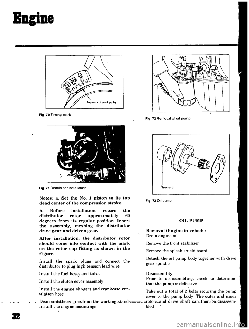
Fig
70
Tlmmg
mark
Fig
71
Dlstnbutor
mstallatlon
Notes
a
Set
the
No
1
piston
to
its
top
dead
center
of
the
compression
stroke
b
Before
installation
return
the
distributor
rotqr
approximately
60
degrees
from
Its
regular
position
Insert
the
assembly
meshing
the
distributor
drive
gear
and
driven
gear
After
installation
the
distributor
rotor
should
come
into
contact
wIth
the
mark
on
the
rotor
cap
fittmg
as
shown
in
the
Figure
Install
the
spark
plugs
and
connect
the
distrIbutor
to
plug
high
tensIOn
lead
wire
Install
the
fuel
hoses
and
tubes
Install
the
clutch
cover
assembly
Install
the
engme
shngers
and
crankcase
ven
tilatIOn
hose
Fig
72
Removal
of
011
pump
TrochoId
Fig
73011
pump
OIL
PUMP
Removal
Engine
in
vehlCIe
Dram
engme
OIl
Remove
the
front
stabilIzer
Remove
the
splash
shield
board
Detach
the
011
pump
body
together
with
drIve
gear
spmdle
Disassembly
PrIor
to
dlsassembhng
check
to
determme
that
the
pump
IS
defective
Take
out
a
total
of
2
bolts
securmg
the
pump
cover
to
the
pump
body
The
outer
and
mner
Dlsmount
the
engme
from
the
workmg
stand
rotors
and
drive
shaft
can
then
be
dlsassem
Install
the
engme
mountmgs
bled
32
Page 33 of 136
ApplYing
a
sUItable
wrench
or
spanner
loosen
off
the
regulator
valve
Note
a
When
placmg
the
valve
m
a
VIse
use
extreme
care
not
to
dIstort
the
pump
body
and
cover
in
the
jaws
b
Do
not
pull
out
the
drive
shaft
pin
securing
the
drIven
shaft
and
inner
rotor
The
shaft
is
press
fitted
to
the
rotor
with
the
pin
calked
Inspection
and
Repair
Clean
the
dIsassembled
parts
with
cleamng
solvent
and
Inspect
for
defects
Inspect
the
dnve
rotor
shaft
for
excessIve
wear
and
scores
and
check
the
follOWing
clearances
SIde
clearance
between
outer
and
Inner
rotors
0
0047
In
or
below
Tip
clearance
00016
to
0
0047
In
Clearance
between
outer
rotor
and
body
o
0059
to
0
0083
In
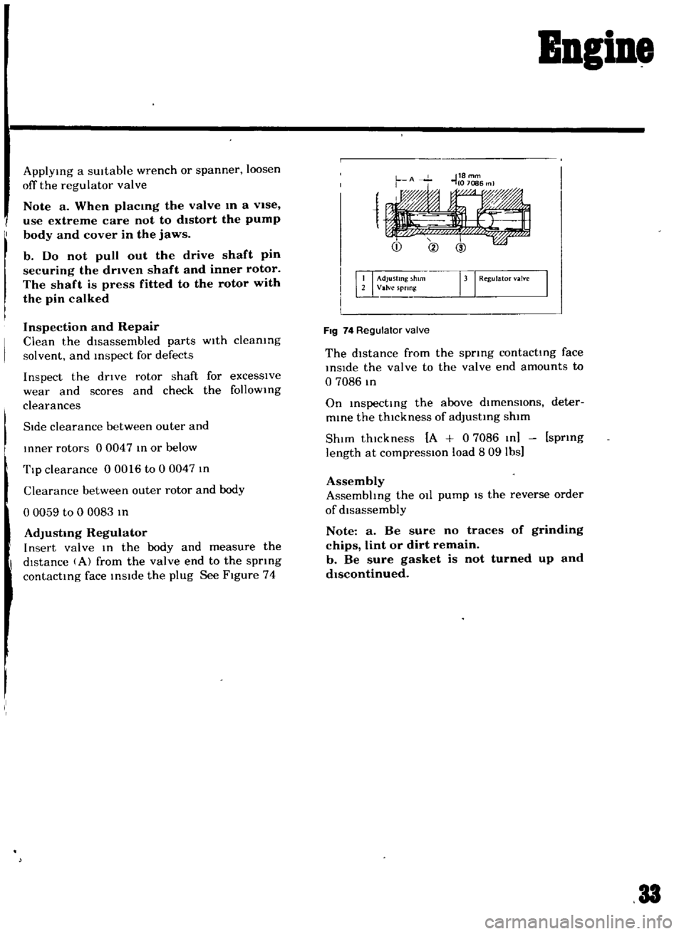
AdjustIng
Regulator
Insert
valve
In
the
body
and
measure
the
dIstance
A
from
the
valve
end
to
the
spnng
contacting
face
inside
the
plug
See
Figure
74
Bngine
1
Adjusting
h
rn
rJ
Regul
m
Valve
spnn
FIg
74
Regulator
valve
The
distance
from
the
spring
contacting
face
inSide
the
valve
to
the
valve
end
amounts
to
o
7086
m
On
inspecting
the
above
dlmenslOns
deter
mine
the
thickness
of
adjusting
shim
ShIm
thickness
A
0
7086
In
spring
length
at
compresslOn
load
809
lbs
Assembly
Assembhng
the
011
pump
IS
the
reverse
order
of
disassembly
Note
a
Be
sure
no
traces
of
grinding
chips
lint
or
dirt
remain
b
Be
sure
gasket
is
not
turned
up
and
dIscontinued
33
Page 36 of 136
B1eetrical
Iptem
Removal
DIsconnect
the
battery
ground
cable
Disconnect
the
black
and
yellow
wIre
from
the
magnetic
sWitch
termmal
and
black
battery
cable
from
the
battery
termmal
Remove
two
bolts
used
to
secure
the
startmg
motor
on
the
clutch
housing
Pull
the
starter
assembly
forward
and
remove
the
starting
motor
Installation
InstallatlOn
IS
the
reversal
of
removal
Removal
Disconnect
the
negatIve
battery
termmal
DIsconnect
two
lead
wires
and
connector
from
the
alternator
Loosen
the
adjusting
bolt
Remove
the
alternator
drIve
belt
Remove
the
alternator
installation
bolt
Dismount
the
alternator
from
the
vehIcle
Installation
InstallatlOn
1S
the
reverse
of
removal
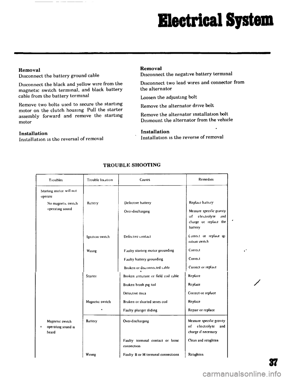
TROUBLE
SHOOTING
Troubles
Trouble
IOl
JlltHI
lartlTlg
motor
will
not
operate
No
mJgnetJl
sWltdl
operating
sound
Rdttcry
IgnitIon
sWltLh
Wiring
Starler
Magnetic
SWitch
Magnetic
SWitch
operating
sound
IS
heard
Bdttery
Wifing
CaUlies
Remedies
Defective
bclttery
Rcpldt
C
bJlh
ry
Over
dlschargmg
Measure
speCific
grJvlty
of
clcl
lrolyte
dnd
chJrge
ur
repl
H
e
the
battery
Defedlvc
lontJd
orreLl
or
replJl
c
Ig
mllun
wltdl
F
lulty
Slartmg
motor
groundlllg
CorrCl
l
F
lUlty
battery
groundmg
Corrcll
Broken
or
dlM
onncdcd
t
Jble
Carrece
or
replJt
c
Broken
dnnJture
or
field
coli
cJble
RcpldCC
Broken
brush
pig
tall
Rcpldce
Dekl
llVe
mll
3
Correcl
or
repldce
Broken
or
shorted
senes
cod
Replace
FaulIy
plunger
slidmg
RepaIr
or
replace
Over
dlschargmg
Measure
speCifiC
gravity
of
electrolyte
and
charge
If
necessary
Faulty
terminal
contact
or
loose
connectIOn
Clean
and
retighten
Faulty
B
or
M
termmal
connections
Rellghten
37
Page 55 of 136
ruel
S
stem
Note
When
somewhat
over
choked
set
bl
metal
cover
after
turning
it
clockwise
slightly
Adjustment
oflnterlock
Opelntng
of
Pnmary
and
Secondary
Throttle
Values
Open
the
pnmary
Side
throttle
valve
48
from
the
fully
closed
positIOn
and
measure
clearance
GIn
between
the
throttle
valve
and
throttle
chamber
mSlde
wall
as
shown
m
Figure
99
GIn
0
228
m
WIthout
dlsturbmg
the
above
settmg
bend
connectmg
rod
as
necessary
so
that
secoridary
throttle
valve
IS
about
to
open
Upon
com
pletIOn
of
the
adjustment
make
sure
that
the
hnk
system
operates
smoothly
Dash
Pot
Adjustment
AutomatIC
Trans
mlsszon
car
only
It
IS
necessary
that
the
Idhng
speed
of
engme
and
mIxture
have
been
well
turned
up
and
engme
IS
suffiC1
n
y
warm
1
Turn
throttle
valve
by
hand
and
read
engme
speed
when
the
da
h
pot
Just
touches
the
stop
per
lever
Adjust
the
pOSitIOn
of
the
dash
pot
by
turnmg
the
nut
until
the
engine
speed
IS
In
the
range
from
1
900
to
2
000
rpm
Make
sure
that
the
engine
speed
IS
smoothly
leduced
from
3
000
to
1
000
rpm
within
a
few
econds
Removal
Remove
the
aIr
cleaner
DIsconnect
the
fuel
line
vacuum
line
automatic
choke
harness
and
antl
dlesehng
solenOId
harness
from
carburetor
Remove
the
throttle
lever
Remove
four
nuts
and
washers
retaining
the
carburetor
to
the
mamfold
If
necessary
LIft
the
carburetor
and
remove
from
the
mamfold
Remove
and
dlscard
the
gasketcused
between
the
carburetor
and
mamfold
8
Disassembly
The
main
Jets
and
needle
valves
on
both
primary
and
secondary
Sides
are
accessible
from
outSIde
of
the
carburetor
for
disassem
bly
Remove
throttle
return
sprmg
Remove
pump
level
shaft
take
out
pump
lever
and
pump
connectmg
rod
Remove
rubber
pipe
from
choke
piston
Loosen
off
bolts
secutlng
servo
diaphragm
In
positIOn
take
out
dIaphragm
Back
off
total
of
five
bolts
which
hold
choke
In
posItion
and
remove
rods
of
starter
system
take
out
choke
chamber
In
removmg
chamber
exercise
care
to
aVOId
damaging
float
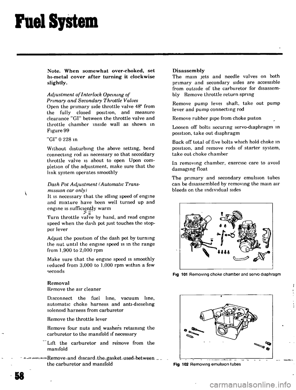
The
pnmary
and
secondary
emulsIOn
tubes
can
be
disassembled
by
removmg
the
main
air
bleeds
on
the
indiVidual
SIdes
UII
ij
Fig
101
Removmg
choke
chamber
and
servo
diaphragm
o
llQt
o
Fig
102
Removmg
emulsion
tubes
Page 65 of 136
Brakes
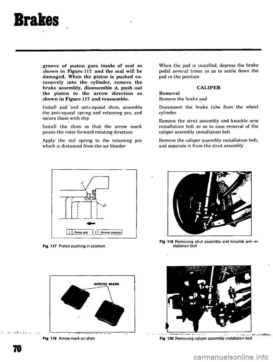
groove
of
pIston
goes
insIde
of
seal
as
shown
in
Figure
117
and
the
seal
will
be
damaged
When
the
piston
is
pushed
ex
cesslvely
mto
the
cylinder
remove
the
brake
assembly
disassemble
It
push
out
the
piston
to
the
arrow
direction
as
shown
in
Figure
117
and
reassemble
Install
pad
and
antt
squeal
shim
assemble
the
anti
squeal
spring
and
retaining
pin
and
ecure
them
with
cltp
Install
the
shim
so
that
the
arrow
mark
pOints
the
rotor
forward
rotating
directIOn
Apply
the
COIl
spring
to
the
retaining
pin
which
IS
distanced
from
the
atr
bleeder
111
PlSton
seal
I
2
I
Normal
position
I
Fig
117
Piston
pushIng
In
posllIon
FIg
118
Arrow
mark
on
shim
78
When
the
pad
IS
Installed
depress
the
brake
pedal
several
tl
mes
so
as
to
settle
down
the
pad
In
the
posltton
CALIPER
Removal
Remove
the
brake
pad
DIsconnect
the
brake
tube
from
the
wheel
cyltnder
Remove
the
strut
assembly
and
knuckle
arm
installatIOn
bolt
so
as
to
ease
removal
of
the
cahper
assembly
installatIOn
bolt
Remove
the
cahper
assembly
installatIOn
bolt
and
separate
It
from
the
strut
assembly
Fig
119
RemOVing
strut
assembly
and
knuckle
arm
in
stallatIon
bolt
Fig
120
RemOVing
caliper
assembly
Installallon
bolt