1968 DATSUN 510 check engine
[x] Cancel search: check enginePage 52 of 252
ENGINE
47
allowable
warpage
IS
0
0039
in
0
I
mm
Standard
should
be
less
than
0
0012
in
O
03mm
In
the
event
the
measurements
are
out
of
tolerance
the
cylmder
head
surface
should
be
milled
or
resurfaced
3
Verify
that
all
water
and
011
passages
are
free
of
foreign
matena
Use
compressed
aIr
to
clean
passages
after
scraping
4
Note
the
condition
of
all
studs
in
the
cylinder
head
Replace
damaged
ones
Valve
Assembly
I
Check
intake
and
exhaust
valve
assembhes
for
worn
damaged
or
deformed
valve
caps
and
stems
Correct
or
replace
the
valve
If
excessive
defects
exist
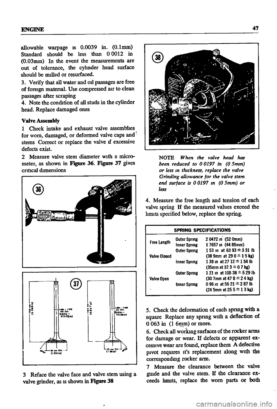
2
Measure
valve
stem
diameter
WIth
a
micro
meter
as
shown
in
Fignre
36
Figure
37
gives
cnncal
drmensions
@
@
Y
lm
1
0
515
r
3
Reface
the
valve
face
and
valve
stem
using
a
valve
grinder
as
18
shown
in
Fignre
38
NOTE
When
the
valve
head
1uzs
been
reduced
to
00197
in
0
Smm
or
less
In
thIckness
replace
the
valve
Grinding
allowance
for
the
valve
stem
end
surface
is
00197
In
0
Smm
or
less
4
Measure
the
free
length
and
tension
of
each
valve
spring
If
the
measured
values
exceed
the
hnuts
specified
below
replace
the
spring
SPRING
SPECIFICATIONS
Free
Length
Outel
Spring
Inner
Spring
Outer
Spring
2
0472
10
52
Omm
1
765710
44
85mm
153m
at6393
331Ib
389mm
at290
15kg
138m
at
2712
154lb
35mm
at12
3
0
7
kg
121
10
at
105
38
5
29
Ib
30
7mm
at
47
8
2
4
kg
09610
at5621
2871b
245mm
at
25
5
13
kg
Valve
Closed
I
nner
Spring
Outer
Spnng
Valve
Open
Inner
Spnng
5
Check
the
deformation
of
each
spnng
with
a
square
Replace
any
spnng
WIth
a
deflection
of
o
063
in
I
611lID
or
more
6
Check
all
workmg
surfaces
of
the
rocker
arms
for
damage
or
wear
If
defects
or
apparent
ex
cessIve
wear
are
found
replace
them
A
defective
PIvot
reqwres
It
S
replacement
along
WIth
the
correspondIng
rocker
ann
7
Measure
the
clearance
between
the
valve
gwde
and
the
valve
stem
If
the
clearance
ex
ceeds
hnuts
replace
the
worn
parts
or
both
Page 54 of 252
ENGINE
49
Cylinder
Block
1
Check
the
cylmder
block
for
defects
such
as
cracks
leaky
soft
plugs
and
blocked
water
pass
ages
Blowout
all
passages
With
compressed
air
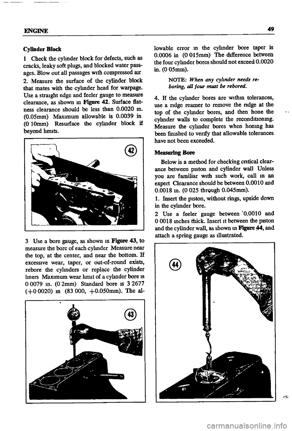
2
Measure
the
surface
of
the
cylinder
block
that
mates
with
the
cyhnder
head
for
warpage
Use
a
straight
edge
and
feeler
gauge
to
measure
clearance
as
shown
m
Figure
42
Surface
flat
ness
clearance
should
be
less
than
0
0020
m
0
05mm
Maxunum
allowable
is
0
0039
in
010mm
Resurface
the
cyhnder
block
if
beyond
hnnts
@
3
Use
a
bore
gauge
as
shown
m
Figure
43
to
measure
the
bore
of
each
cyhnder
Measure
near
the
top
at
the
center
and
near
the
bottom
If
excessive
wear
taper
or
out
of
round
exists
rebore
the
cyhnders
or
replace
the
cylinder
hners
Maxunum
wear
hnnt
of
a
cyhnder
bore
IS
o
0079
m
0
2mm
Standard
bore
IS
3
2677
0
0020
m
83
000
0
050mm
The
al
@
lowable
error
m
the
cyhnder
bore
taper
is
0
0006
in
0015mm
The
difference
between
the
four
cyhnder
bores
should
not
exceed
0
0020
in
0
05mm
NOTE
When
any
cylmder
needs
re
boring
all
foUT
must
be
rebored
4
If
the
cyhnder
bores
are
Wlthm
tolerances
use
a
ndge
reamer
to
remove
the
ndge
at
the
top
of
the
cyhnder
bores
and
then
hone
the
cyhnder
walls
to
complete
the
recolllhuonmg
Measure
the
cyhnder
bores
when
honmg
has
been
finished
to
venfy
that
allowable
tolerances
have
not
been
exceeded
Measuring
Bore
Below
is
a
method
for
checking
cntical
clear
ance
between
piston
and
cylinder
wall
Unless
you
are
familiar
With
such
work
call
m
an
expert
Clearance
should
be
between
0
0010
and
0
0018
m
0025
thrQugh
0
045mm
1
Insert
the
pISton
without
rings
upside
down
in
the
cyhnder
bore
2
Use
a
feeler
gauge
between
0
0010
and
00018
mches
thick
Insert
It
between
the
pISton
and
the
cylinder
wall
as
shown
m
Figure
and
attach
a
spring
gauge
as
illustrated
@
Page 56 of 252
ENGINE
51
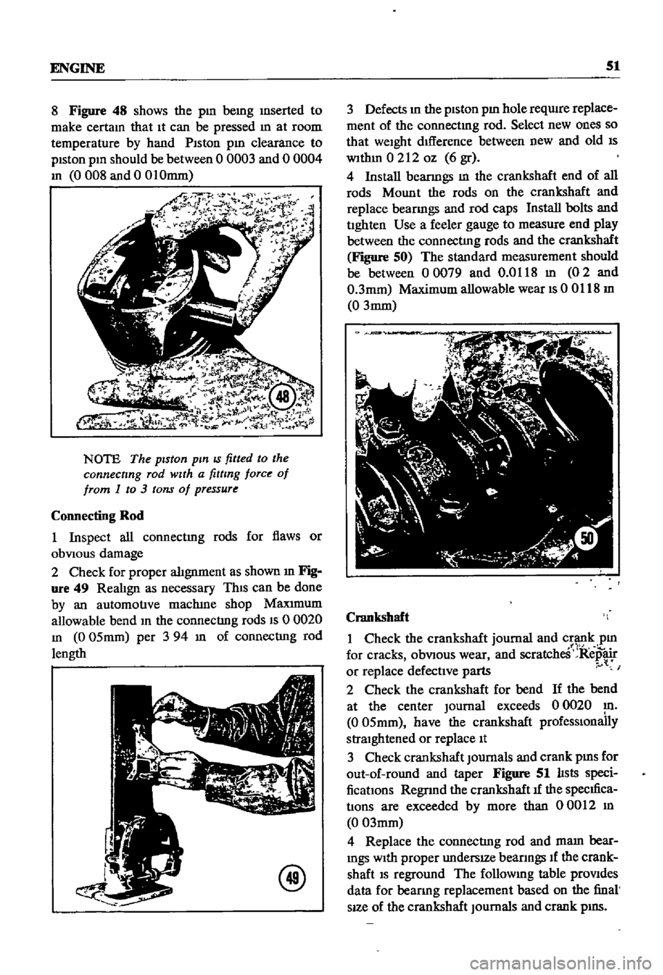
8
Figure
48
shows
the
pm
bemg
mserted
to
make
certam
that
It
can
be
pressed
m
at
room
temperature
by
hand
Piston
pm
clearance
to
piston
pm
should
be
between
0
0003
and
0
0004
m
0008
and
0
01Omm
NOTE
The
piston
pin
IS
fitted
to
the
connecting
rod
with
a
fitting
force
of
from
1
to
3
tons
of
pressure
Connecting
Rod
1
Inspect
all
connectmg
rods
for
flaws
or
obVIOUS
damage
2
Check
for
proper
alignment
as
shown
m
Fig
ure
49
RealIgn
as
necessary
ThIS
can
be
done
by
an
automotive
maclune
shop
Maxrmum
allowable
bend
m
the
connecting
rods
IS
0
0020
m
0
05mm
per
3
94
m
of
connecting
rod
length
@
3
Defects
m
the
piston
pm
hole
reqwre
replace
ment
of
the
connectmg
rod
Select
new
ones
so
that
weight
dIfference
between
new
and
old
IS
wlthm
0212
oz
6
gr
4
Install
beanngs
m
the
crankshaft
end
of
all
rods
Mount
the
rods
on
the
crankshaft
and
replace
beanngs
and
rod
caps
Install
bolts
and
tighten
Use
a
feeler
gauge
to
measure
end
play
between
the
connecting
rods
and
the
crankshaft
Figure
50
The
standard
measurement
should
be
between
00079
and
0
0118
m
02
and
0
3mm
Maximum
allowable
wear
IS
00118
m
0
3mm
Crankshaft
1
Check
the
crankshaft
journal
and
crank
pm
1
1
for
cracks
obVIOUS
wear
and
scratcheS
Repair
or
replace
defective
parts
I
2
Check
the
crankshaft
for
bend
If
the
bend
at
the
center
Journal
exceeds
0
0020
m
0
05mm
have
the
crankshaft
prOfeSSIOnally
straightened
or
replace
It
3
Check
crankshaft
Journals
and
crank
pms
for
out
of
round
and
taper
Figure
51
lIsts
speci
fications
Regnnd
the
crankshaft
1f
the
specIfica
tions
are
exceeded
by
more
than
00012
m
0
03mm
4
Replace
the
connecting
rod
and
mam
bear
mgs
With
proper
undersIZe
beanngs
If
the
crank
shaft
IS
reground
The
followmg
table
prOVides
data
for
beanng
replacement
based
on
the
final
sIZe
of
the
crankshaft
Journals
and
crank
pIllS
Page 58 of 252
ENGINE
53
the
mam
beanng
cap
and
the
cyhnder
block
beanng
recess
and
tighten
the
cap
bolts
to
the
proper
torque
WIth
a
torque
wrench
Tig
temng
torque
Main
bearings
506
to
57
8
It
Ib
70to80kg
m
195
to
23
9
It
Ib
27
to3
3
kg
m
Rod
beanngs
9
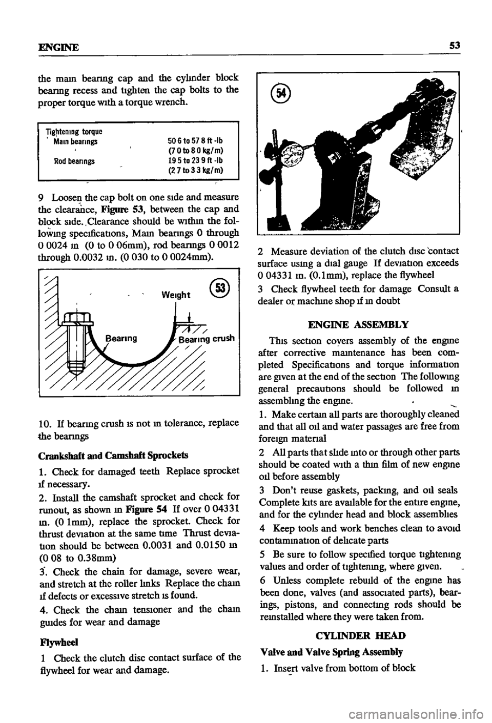
Loosen
the
cap
bolt
on
one
Side
and
measure
the
clearance
Figure
53
between
the
cap
and
block
Side
Clearance
should
be
WIthm
the
fol
lowmg
specmcatIons
Mam
beanngs
0
through
o
0024
m
0
to
0
06mm
rod
beanngs
00012
through
0
0032
m
0
030
to
0
0024mm
Weight
@
10
If
beanng
crush
IS
not
m
tolerance
replace
the
beanngs
Crankshaft
and
Camshaft
Sprockets
1
Check
for
damaged
teeth
Replace
sprocket
1f
necessary
2
Install
the
camshaft
sprocket
and
check
for
runout
as
shown
m
Figure
54
If
over
0
04331
m
0
Imm
replace
the
sprocket
Check
for
thrust
deViation
at
the
same
tIme
Thrust
deVia
tIOn
should
be
between
0
0031
and
0
0150
m
008
to
0
38mm
3
Check
the
chain
for
damage
severe
wear
and
stretch
at
the
roller
hnks
Replace
the
cham
1f
defects
or
exceSSIve
stretch
IS
found
4
Check
the
cham
tenslOner
and
the
cham
gwdes
for
wear
and
damage
Flywheel
1
Check
the
clutch
disc
contact
surface
of
the
flywheel
for
wear
and
damage
@
2
Measure
deviation
of
the
clutch
disc
contact
surface
usmg
a
dial
gauge
If
deVIation
exceeds
004331
m
O
lmm
replace
the
flywheel
3
Check
flywheel
teeth
for
damage
Consult
a
dealer
Or
machIne
shop
1f
m
doubt
ENGINE
ASSEMBLY
This
section
covers
assembly
of
the
engme
after
corrective
mamtenance
has
been
com
pleted
SpecificatIons
and
torque
informatIon
are
given
at
the
end
of
the
sectIon
The
followmg
general
precautions
should
be
followed
m
assembhng
the
engme
1
Make
certam
all
parts
are
thoroughly
clean
and
that
all
011
and
water
passages
are
free
from
foreign
matenal
2
All
parts
that
slIde
mto
or
through
other
parts
should
be
coated
With
a
thm
film
of
new
engme
011
before
assembly
3
Don
t
reuse
gaskets
packIng
and
011
seals
Complete
lats
are
aVlUlable
for
the
entire
engme
and
for
the
cyhnder
head
and
block
assemblIes
4
Keep
tools
and
work
benches
clean
to
aVOid
contammatlon
of
delIcate
parts
5
Be
sure
to
follow
specmed
torque
tIghtenmg
values
and
order
of
tlghtenmg
where
given
6
Unless
complete
rebwld
of
the
engme
has
been
done
valves
and
associated
parts
bear
ings
pistons
and
connectIng
rods
should
be
remstalled
where
they
were
taken
from
CYLINDER
HEAD
Valve
and
Valve
Spring
Assembly
1
Insert
valve
from
bottom
of
block
Page 59 of 252
54
CHAP1ER
SIX
2
Set
the
valve
spnng
seat
m
position
on
the
top
of
the
block
and
over
the
valve
stem
3
Place
the
oil
seal
over
the
valve
stem
4
Place
the
mner
and
outer
valve
spnngs
over
the
valve
stem
S
Place
the
spnng
retamer
over
the
springs
compress
spnngs
With
spring
compressor
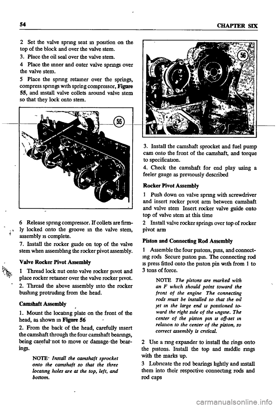
Figure
55
and
mstall
valve
collets
around
valve
stem
so
that
they
lock
onto
stem
6
Release
spnng
compressor
If
collets
are
firm
ly
locked
onto
the
groove
m
the
valve
stem
assembly
IS
complete
7
Install
the
rocker
guIde
on
top
of
the
valve
stem
when
assemblmg
the
rocker
pivot
assembly
VaIve
Rocker
Pivot
Assembly
1
Thread
lock
nut
onto
valve
rocker
pivOt
and
place
rocker
retaIner
over
the
valve
rocker
pivOt
2
Thread
the
above
assembly
mto
the
rocker
bushIng
protrudIng
from
the
head
Camshaft
Assembly
1
Mount
the
locatIng
plate
on
the
front
of
the
head
as
shown
m
FJgIlI
1
56
2
From
the
back
of
the
head
carefully
InSert
the
camshaft
through
the
four
camshaft
beanngs
being
ca
efu1
not
to
move
or
damage
the
bear
ings
NOTE
Install
the
CQJ7IShaft
sprocket
onto
the
camshaft
so
that
the
three
locating
holes
are
at
the
top
left
and
bottom
h
1
3
Install
the
camshaft
sprocket
and
fuel
pump
cam
onto
the
front
of
the
camshaft
and
torque
to
specificatIon
4
Check
the
camshaft
for
end
play
using
a
feeler
gauge
as
preViously
described
Rocker
Pivot
Assembly
1
Push
down
on
valve
spnng
with
screwdriver
and
insert
rocker
piVOt
arm
between
camshaft
and
valve
stem
Insert
rocker
valve
guide
onto
top
of
valve
stem
at
this
time
2
Install
valve
rocker
springs
over
top
of
rocker
pivot
arm
Piston
and
Connecting
Rod
Assembly
1
Assemble
the
four
pistons
pms
and
connect
mg
rods
Secure
piston
pm
The
connecting
rod
IS
press
fitted
onto
the
pISton
pin
With
from
1
to
3
tons
of
force
NOTE
The
pistons
are
marked
with
an
F
which
should
point
toward
the
front
of
the
engine
The
connecting
rods
must
be
installed
so
that
the
011
Jet
In
the
large
end
IS
positioned
to
ward
the
right
Side
of
the
tnglne
The
center
of
the
piston
pin
IS
oD
set
In
relation
to
the
center
of
the
piston
so
correct
assembly
is
cntical
2
Use
a
nng
expander
to
install
the
rings
onto
the
pistons
Install
the
top
and
rmddle
nngs
with
the
marks
up
3
Lubncate
the
rod
bearings
hghtly
and
mstall
them
into
their
respective
connectIng
rods
and
rod
caps
Page 60 of 252

ENGINE
55
Cylinder
Block
Assembly
1
PositIon
all
crankshaft
parts
on
a
work
bench
ThIS
mcludes
the
crankshaft
main
beanngs
rear
011
seal
woodruff
keys
crankshaft
gear
011
pump
gear
011
thrower
bolts
and
bearing
caps
Figure
57
shows
the
arrangement
@
2
Insert
maIO
beanngs
mto
appropnate
cy1m
der
block
holders
NOTE
The
center
No
3
beanng
IS
the
only
flanged
type
of
thrust
bear
Ing
Bearings
No
2
and
No
4
are
Identical
No
1
and
No
5
Jaring
ap
pear
identical
but
No
1
as
an
011
hole
All
bearings
except
No
1
are
Interchangeable
as
to
upper
and
lower
half
3
LIghtly
lubncate
the
crankshaft
and
beanng
matmg
surfaces
then
mstall
beanngs
10
mam
beanng
caps
4
Install
the
crankshaft
5
Install
mam
beanng
caps
over
crankshaft
msert
mam
cap
bolts
and
tighten
hghtly
The
mam
beanng
caps
have
an
arrow
marked
on
each
one
These
must
pomt
to
the
front
of
the
engme
6
Gently
move
the
crankshaft
10
an
aXIal
drrec
don
toward
the
front
of
the
engme
to
venfy
that
the
mam
beanng
caps
are
properly
alIgned
and
seated
7
Use
a
torque
wrench
to
tighten
the
cap
bolts
to
the
hmlts
speCIfied
The
t1ghtenmg
operatIon
should
be
done
gradually
10
three
or
four
sep
arate
stages
starting
10
the
center
and
workmg
outward
to
each
end
8
Rotate
the
crankshaft
to
make
certain
it
isn
t
bmding
9
Use
a
feeler
gauge
to
check
the
end
play
at
the
center
No
3
beanng
Figure
58
10
Install
the
SIde
oll
seals
into
the
rear
mam
cap
and
cy1mder
block
as
shown
10
Figure
59
@
11
Install
the
rear
011
seal
WIth
Datsun
tool
ST49370000
or
equIvalent
12
Install
the
rear
end
plate
13
Install
the
flywheel
WIth
proper
bolts
and
lock
washers
and
torque
as
specified
Page 61 of 252
56
CHAPTER
SIX
NOTE
Lubncate
the
cylinder
walls
with
new
engine
oil
prior
to
insertIOn
of
pistOns
Make
certain
that
the
ring
gaps
are
not
In
line
wIth
one
another
Place
the
gaps
180
degrees
from
each
other
and
not
posltloned
either
front
to
back
or
dIrectly
in
line
with
the
piston
pIns
CAUTION
Use
extreme
care
when
Inserting
pzs
tons
so
as
to
avoId
crankshaft
damage
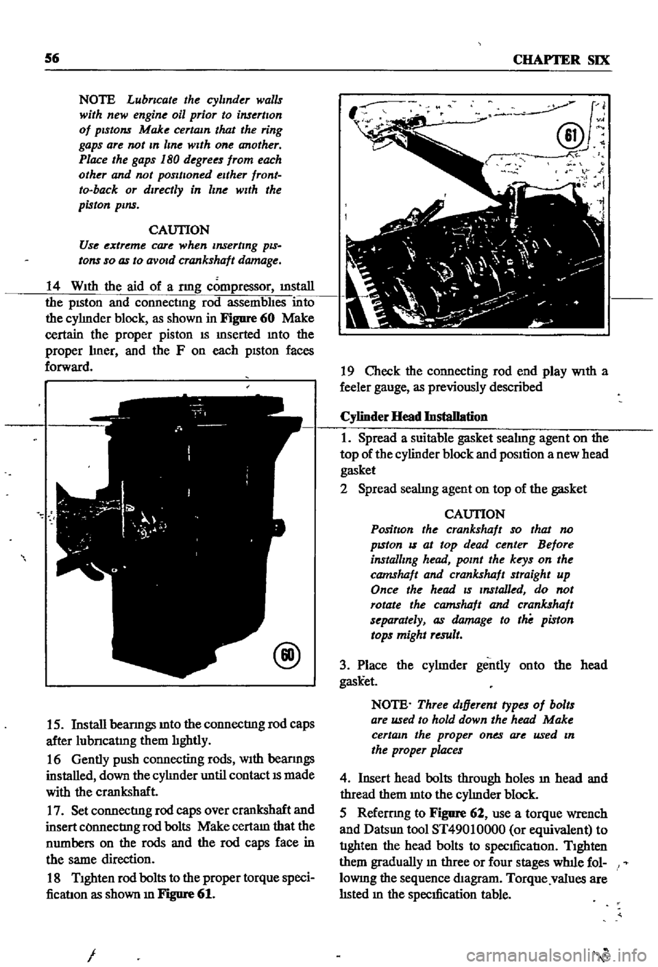
14
With
the
aid
of
a
nng
compressor
illStaIl
the
pISton
and
connectmg
rod
assembhes
into
the
cyhnder
block
as
shown
in
Figure
60
Make
certain
the
proper
piston
IS
mserted
mto
the
proper
hner
and
the
F
on
each
pISton
faces
forward
@
15
Install
beanngs
mto
the
connectIng
rod
caps
after
lubncatmg
them
hghtly
16
Gently
push
connecting
rods
With
beanngs
installed
down
the
cyhnder
until
contact
IS
made
with
the
crankshaft
17
Set
connectIng
rod
caps
over
crankshaft
and
insert
COnnectIng
rod
bolts
Make
certam
that
the
numbers
on
the
rods
and
the
rod
caps
face
in
the
same
direction
18
Tighten
rod
bolts
to
the
proper
torque
speci
ficatIon
as
shown
m
Figure
61
I
J
@v
N
i
19
Check
the
connecting
rod
end
play
With
a
feeler
gauge
as
previously
described
Cylinder
Head
Installation
1
Spread
a
suitable
gasket
seahng
agent
on
the
top
of
the
cylinder
block
and
position
a
new
head
gasket
2
Spread
seahng
agent
on
top
of
the
gasket
CAUTION
PositIon
the
crankshaft
so
that
no
pzston
IS
at
top
dead
center
Before
installing
head
point
the
keys
on
the
camshaft
and
crankshaft
straight
up
Once
the
head
zs
Installed
do
not
rotate
the
camshaft
and
crankshaft
separately
as
damage
to
the
piston
tops
might
result
3
Place
the
cyhnder
gently
onto
the
head
gask
et
NOTE
Three
dIfferent
types
of
bolts
are
used
to
hold
down
the
head
Make
certain
the
proper
ones
are
used
In
the
proper
places
4
Insert
head
bolts
through
holes
ill
head
and
thread
them
mto
the
cyhnder
block
5
Refemng
to
Figure
62
use
a
torque
wrench
and
Datsun
tool
ST49010000
or
equivalent
to
tIghten
the
head
bolts
to
specIficatIon
Tighten
them
gradually
m
three
or
four
stages
wlnle
fol
lOWIng
the
sequence
diagram
Torque
values
are
hsted
m
the
specIfication
table
Page 76 of 252
FUEL
SYSTEM
71
Dash
Pot
Adjustment
The
adjustment
of
the
dash
pot
IS
done
by
warmmg
up
the
engme
properly
and
checkIng
If
the
throttle
lever
touches
th
dash
pot
stem
as
the
engine
reaches
1
800
and
2
000
rpm
under
no
load
conditIons
Proper
contact
between
the
throttle
lever
and
the
dash
pot
stem
produces
a
normal
dash
pot
performance
Should
a
normal
mcrease
m
engme
speed
not
occur
adjust
the
dash
pot
as
follows
1
Loosen
the
dash
pot
locknuts
2
Rotate
the
dash
pot
nght
and
then
left
3
Adjust
the
dash
pot
so
that
the
throttle
lever
hIts
the
stem
between
1
800
and
2
000
rpm
4
Fasten
the
lock
nuts
securely
5
The
clearance
between
the
throttle
valve
and
the
throttle
chamber
wall
should
be
0
0709
m
0
8mm
or
10
degrees
In
throttle
valve
angle
MAJOR
CARBURETOR
SERVICE
PROCEDURES
A
carburetor
m
good
operatIng
condition
will
delIver
the
pr
per
gasolme
and
aIr
ratIos
for
all
engme
runnmg
speeds
A
gradual
declme
In
smoothness
response
and
power
Will
occur
as
the
carburetor
slIps
from
adjustment
and
Its
delI
cate
parts
become
dirty
and
worn
Overhaul
should
only
be
attempted
by
an
expenenced
mechanic
Accurate
calIbratIon
of
passages
and
dIS
charge
hole
reqUIre
that
extreme
care
be
taken
In
dISassembly
cleanmg
and
reassembly
Use
only
a
hIgh
grade
carburetor
cleaner
and
com
pressed
arr
to
clean
parts
and
passages
Never
use
wire
or
other
pOInted
Instruments
for
clean
ing
CalIbratIon
of
the
carburetor
will
be
af
fected
The
procedures
below
are
generally
true
for
all
models
As
an
aId
Figures
13
and
14
are
typIcal
examples
of
the
carburetors
used
Carburetor
Removal
1
Remove
the
au
cleaner
by
dIsconnectIng
all
hoses
attached
to
It
remoVmg
the
two
bolts
holdmg
the
aIr
cleaner
to
the
support
and
loos
enmg
the
band
bolt
at
the
base
of
the
aIr
cleaner
2
DIsconnect
fuellme
vacuum
Ime
and
choke
wire
u
eqUIpped
from
the
carburetor
3
Remove
the
throttle
lever
4
Remove
four
nuts
and
washers
holdmg
car
buretor
to
manIfold
5
Lift
carburetor
off
of
manuold
6
Remove
and
dIscard
carburetor
to
manuold
gasket
7
Place
carburetor
on
clean
workbench
Carburetor
Disassembly
1
The
maIn
Jets
slow
Jets
and
needle
valves
on
both
the
pnmary
and
secondary
systenIS
are
accessIble
from
outsIde
the
carburetor
Refer
to
FIgures
13
and
14
for
locatI
n
2
The
choke
chamber
can
be
detached
by
re
mOVIng
the
connectIng
rod
pump
connectIng
rod
return
sprmg
stop
pm
and
the
set
screws
I
that
hold
It
in
place
3
The
pnmary
and
secondary
emulSIon
tubes
can
be
disassembled
by
remOVIng
the
mam
air
bleeds
on
the
respectIve
SIdes
4
To
check
the
accelerator
pump
remove
the
cylInder
cover
Be
careful
not
to
lose
the
return
spnng
and
Inlet
valve
at
the
lower
part
of
the
pIston
durmg
dIsassembly
5
Detach
the
throttle
chamber
from
the
float
chamber
by
remOVIng
the
rod
lInkIng
the
dia
phragm
WIth
the
secondary
throttle
valve
and
the
four
screws
that
hold
It
However
It
IS
preferable
to
leave
the
throttle
valve
mtact
unless
absolutely
reqUired
If
It
IS
necessary
to
dlS
assemble
the
valve
It
should
be
Installed
so
that
the
secondary
throttle
valve
will
be
gap
free
OtherwIse
stable
Idle
and
good
slow
speed
performance
will
suffer
is
To
check
the
float
the
float
chamber
cover
must
be
removed
I
7
The
dIaphragm
IS
dIsassembled
by
removing
the
set
screws
holdmg
the
dIaphragm
chamber
cover
In
reassemblIng
the
diaphragm
be
careful
not
to
turn
the
edge
of
the
dIaphragm
up
8
In
dlsassemblmg
and
reassembling
the
mter
lockIng
lInks
take
care
so
that
each
lInkage
has
a
smooth
actIon
and
that
parts
are
not
forced
mto
pOSItIon
9
For
vehIcles
equipped
With
an
automatIc
choke
remove
the
brmetal
case
by
releasmg
the
set
screws
The
bimetal
1l
extremely
senSItIve