1968 DATSUN 510 check engine
[x] Cancel search: check enginePage 94 of 252
COOLING
SYSTEM
89
FAN
CLUTCH
Fan
Clutch
Operation
and
Inspection
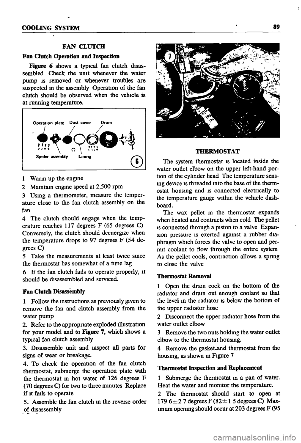
Figure
6
shows
a
typICal
fan
clutch
dISas
sembled
Check
the
umt
whenever
the
water
pump
IS
removed
or
whenever
troubles
are
suspected
m
the
assembly
OperatIon
of
the
fan
clutch
should
be
observed
when
the
vehIcle
is
at
nmning
temperature
Operation
plate
Dust
cover
Drum
o9
Q
SpIder
assembly
LIning
CD
1
Warm
up
the
engme
2
MaIntam
engIne
speed
at
2
500
rpm
3
Usmg
a
thermometer
measure
the
temper
ature
close
to
the
fan
clutch
assembly
on
the
fan
4
The
clutch
should
engage
when
the
temp
erature
reaches
17
degrees
F
65
degrees
C
Conversely
the
clutch
should
deenergIze
when
the
temperature
drops
to
97
degrees
F
54
de
grees
C
5
Take
the
measurements
at
least
twice
SInce
the
thermostat
has
somewhat
of
a
tlme
lag
6
If
the
fan
clutch
falls
to
operate
properly
It
should
be
dIsassembled
and
servIced
Fan
Clutch
Disassembly
1
Follow
the
mstructIons
as
prevIOusly
gIven
to
remove
the
fan
and
clutch
assembly
from
the
water
pump
2
Refer
to
the
appropnate
exploded
illustratIon
for
your
model
and
to
Figure
7
which
shows
a
typiCal
fan
clutch
assembly
3
DIsassemble
unit
and
mspect
all
parts
for
signs
of
wear
or
breakage
4
To
check
the
operatIon
of
the
fan
clutch
thermostat
submerge
the
operatIon
plate
With
the
thermostat
In
hot
water
of
126
degrees
F
70
degrees
C
for
two
to
three
mmutes
Replace
if
It
faIls
to
operate
5
Assemble
the
fan
clutch
m
the
reverse
order
o
dIsassembly
THERMOSTAT
The
system
thermostat
IS
located
inside
the
water
outlet
elbow
on
the
upper
left
hand
por
bon
of
the
cylInder
head
The
temperature
sens
Ing
deVice
IS
threaded
Into
the
base
of
the
therm
ostat
housmg
and
IS
connected
electrlcally
to
the
temperature
gauge
WIthIn
the
vehIcle
dash
board
The
wax
pellet
m
the
thermostat
expands
when
heated
and
contracts
when
cold
The
pellet
IS
connected
through
a
pIston
to
a
valve
Expan
sion
pressure
IS
exerted
agalUst
a
rubber
dIa
phragm
which
forces
the
valve
to
open
and
per
rrut
coolant
to
flow
through
the
entIre
system
As
the
pellet
cools
contractIOn
allows
a
spnng
to
close
the
valve
Thermostat
Removal
1
Open
the
draIn
cock
on
the
bottom
of
the
radiator
and
dram
out
enough
coolant
so
that
the
level
In
the
radIator
IS
below
the
bottom
of
the
upper
radIator
hose
2
DIsconnect
the
upper
radIator
hose
from
the
water
outlet
elbow
3
Remove
the
two
nuts
holdIng
the
water
outlet
elbow
to
the
thermostat
housmg
4
Remove
the
gasket
and
thermostat
from
the
housmg
as
shown
m
FIgure
7
Thermostat
Inspection
and
Replacement
Submerge
the
thermostat
In
a
pan
of
water
Heat
the
water
and
momtor
the
temperature
2
The
thermostat
should
start
to
open
at
1796
1
27
degrees
F
82
1
1
5
degrees
C
Max
Imum
opemng
should
occur
at
203
degrees
F
95
Page 100 of 252
ENGINE
ELECI
RlCAL
SYSTEM
9S
@
@
4
Test
the
COIls
for
shorts
by
unsoldermg
the
connectIons
of
each
coIl
and
repeatlng
the
test
given
m
step
3
If
a
defectIve
coil
IS
found
It
must
be
replaced
BRUSHES
AND
BRUSH
LEAD
WIRE
1
Check
condItIon
of
the
brush
contact
surface
and
general
wear
of
the
brush
If
the
brush
is
worn
to
under
02362
In
60mm
m
length
replace
It
Inspect
all
connectIons
carefully
for
looseness
or
cracks
Replace
or
reparr
as
re
qUIred
2
Check
the
connectIon
of
the
lead
clIp
and
WIre
3
Check
brush
holders
and
sprmg
clIps
for
damage
Replace
1f
they
will
not
hold
the
brushes
agaInst
the
commutator
properly
Clean
all
brushes
aIld
brush
holders
thoroughly
4
Check
brush
sprmg
tenSIon
WIth
a
spnng
scale
as
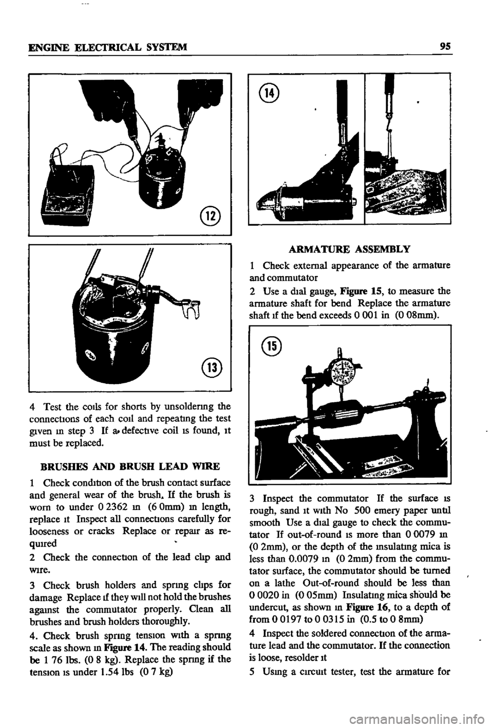
shown
m
Figure
14
The
reading
should
be
1
76
Ibs
0
8
kg
Replace
the
spnng
if
the
tenSIon
IS
under
1
54
Ibs
0
7
kg
@
ARMATURE
ASSEMBLY
1
Check
external
appearance
of
the
armature
and
commutator
2
Use
a
dIal
gauge
Figure
15
to
measure
the
armature
shaft
for
bend
Replace
the
armature
shaft
1f
the
bend
exceeds
0
001
in
0
08mm
@
3
Inspect
the
commutator
If
the
surface
IS
rough
sand
It
With
No
500
emery
paper
untIl
smooth
Use
a
dIal
gauge
to
check
the
commu
tator
If
out
of
round
IS
more
than
00079
In
0
2mm
or
the
depth
of
the
Insulatlng
mica
is
less
than
0
0079
In
0
2mm
from
the
commu
tator
surface
the
commutator
should
be
turned
on
a
lathe
Out
of
round
should
be
less
than
o
0020
in
0
05mm
Insulatmg
mica
should
be
undercut
as
shown
m
Figure
16
to
a
depth
of
from
0
0197
to
0
0315
in
0
5
to
0
8mm
4
Inspect
the
soldered
connectIon
of
the
arma
ture
lead
and
the
commutator
If
the
connection
is
loose
resolder
It
5
Usmg
a
clrcmt
tester
test
the
armature
for
Page 102 of 252
ENGINE
ELECI
RlCAL
SYSTEM
97
No
Load
Lock
Torque
Test
1
Connect
the
starter
motor
in
series
with
a
12
volt
battery
and
antmeter
as
shown
in
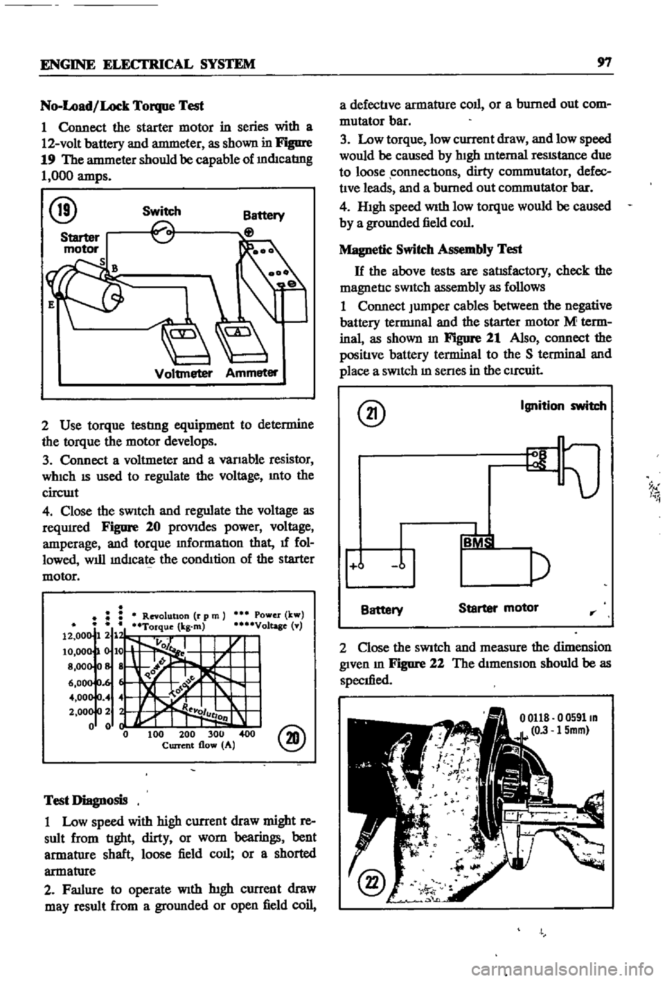
Figure
19
The
antmeter
should
be
capable
of
mdIcatIng
1
000
amps
@
Switch
Voltmeter
Ammeter
2
Use
torque
testlng
equipment
to
determine
the
torque
the
motor
develops
3
Connect
a
voltmeter
and
a
vanable
resistor
WhICh
IS
used
to
regulate
the
voltage
Into
the
circwt
4
Close
the
sWitch
and
regulate
the
voltage
as
reqUIred
Figure
20
proVIdes
power
voltage
amperage
and
torque
mformatIon
that
1f
fol
lowed
will
mdIcate
the
condItion
of
the
starter
motor
Power
kw
Voltage
v
@
Test
Diagnosis
1
Low
speed
with
high
current
draw
might
re
sult
from
tIght
dirty
or
worn
bearings
bent
armatlIre
shaft
loose
field
call
or
a
shorted
armatlIre
2
Fatlure
to
operate
With
htgh
current
draw
may
result
from
a
gromlded
or
open
field
coil
a
defectIve
armature
coll
or
a
burned
out
com
mutator
bar
3
Low
torque
low
current
draw
and
low
speed
would
be
caused
by
hIgh
Internal
reSIStance
due
to
loose
connectIons
dirty
commutator
defec
tIve
leads
and
a
burned
out
commutator
bar
4
HIgh
speed
With
low
torque
would
be
caused
by
a
grounded
field
coll
Magnetic
Switch
Assembly
Test
H
the
above
tests
are
satIsfactory
check
the
magnetIc
SWitch
assembly
as
follows
1
Connect
Jumper
cables
between
the
negative
battery
tennmal
and
the
starter
motor
M
term
inal
as
shown
In
Figure
21
Also
connect
the
positIve
battery
terminal
to
the
S
terminal
and
place
a
SWitch
m
senes
in
the
CIrCuit
@
Ignition
switch
9
I
i
j
Battery
Starter
motor
rr
2
Close
the
SWitch
and
measure
the
dimension
given
m
Figure
22
The
dimensIon
should
be
as
specIfied
o
0591m
15mm
Page 108 of 252
ENGINE
ELECTRICAL
SYSTEM
103
2
Check
the
lead
Wires
of
the
armature
coil
Includmg
the
neutral
wire
for
ground
as
shown
In
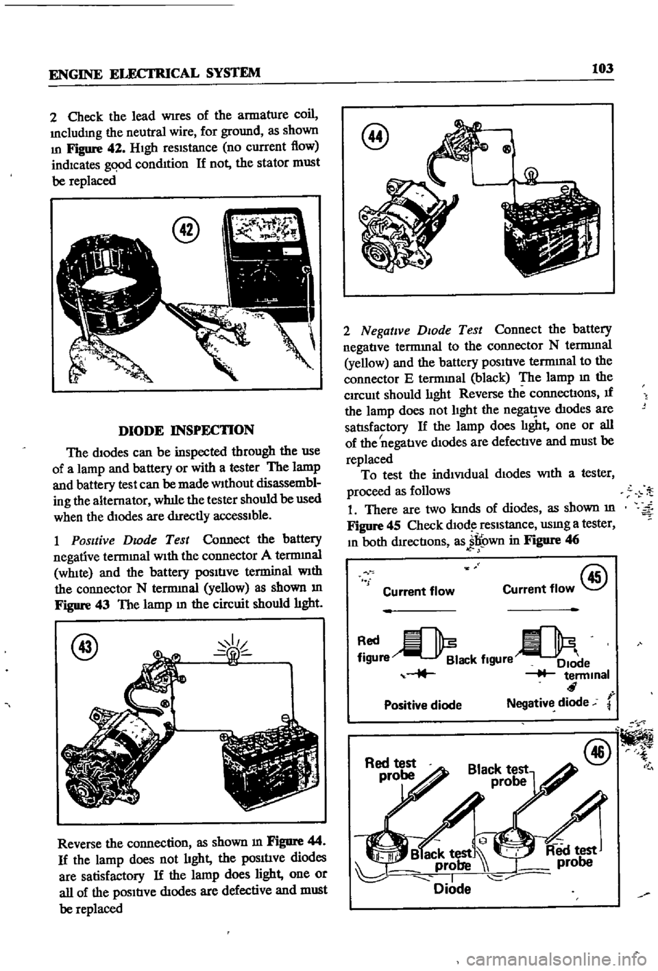
Figure
42
HIgh
reSIStance
no
current
flow
indicates
gqod
condItion
If
not
the
stator
must
be
replaced
DIODE
INSPECTION
The
diodes
can
be
inspected
through
the
use
of
a
lamp
and
battery
or
with
a
tester
The
lamp
and
battery
test
can
be
made
Without
disassembl
ing
the
alternator
wh1le
the
tester
should
be
used
when
the
dIodes
are
dIrectly
acceSSIble
1
Positive
Dwde
Test
Connect
the
battery
negative
terrmnal
WIth
the
connector
A
terrmnal
WhIte
and
the
battery
pOSItIve
terminal
With
the
connector
N
terrmnal
yellow
as
shown
m
Figure
43
The
lamp
m
the
circuit
should
hght
@
Reverse
the
connection
as
shown
m
Figure
44
If
the
lamp
does
not
hght
the
pOSItIve
diodes
are
satisfactory
If
the
lamp
does
light
one
or
all
of
the
pOSItIve
dIodes
are
defective
and
must
be
replaced
@
Qg
2
Negative
DIOde
Test
Connect
the
battery
negatIve
termmal
to
the
connector
N
terrmnal
yellow
and
the
battery
pOSItIve
termInal
to
the
connector
E
termmal
black
The
lamp
m
the
CIrcUit
should
lIght
Reverse
the
connectIons
If
the
lamp
does
not
lIght
the
nega1
ve
dIodes
are
satlsfactory
If
the
lamp
does
lIght
one
or
all
I
of
the
negatIve
dIodes
are
defectIve
and
must
be
replaced
To
test
the
indiVIdual
dIodes
With
a
tester
proceed
as
follows
1
There
are
two
kInds
of
diodes
as
shown
m
Figure
45
Check
dlOd
reSIstance
usmg
a
tester
In
both
dIrectIons
as
jl
own
in
Figure
46
f
Current
flow
@
Current
flow
re
ack
flgUre
e
terminal
r
Positive
diode
Negative
diode
@
Page 111 of 252
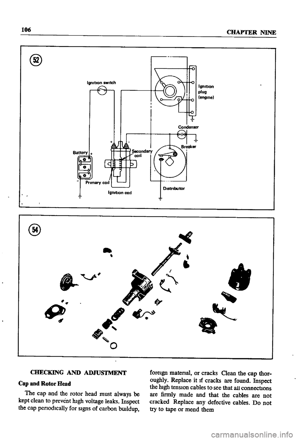
106
CHAPTER
NINE
@
Igmtlon
switch
IgnItion
plug
engine
Condenser
IgnItIon
cod
@
II
9
ft
O
CHECKING
AND
ADJUSTMENT
foreIgn
matenal
or
cracks
Qean
the
cap
thor
oughly
Replace
it
If
cracks
are
found
Inspect
the
hIgh
tensIon
cables
to
see
that
all
connectIons
are
firmly
made
and
that
the
cables
are
not
cracked
Replace
any
defective
cables
Do
not
try
to
tape
or
mend
them
Cap
and
Rotor
Head
The
cap
and
the
rotor
head
must
always
be
kept
clean
to
prevent
lugh
voltage
leaks
Inspect
the
cap
penod1cally
for
SIgnS
of
carbon
bwldup
Page 119 of 252
CHAPTER
TEN
EMISSION
CONTROL
SYSTEM
ThIs
chapter
covers
emission
control
and
exhaust
systems
The
emission
devices
used
in
clude
crankcase
ermssion
controls
an
exhaust
ermssion
system
and
evaporative
emission
con
trols
EXHAUST
EMISSION
CONTROL
SYSTEM
Two
methods
of
exhaust
emission
control
are
used
on
the
Datsun
One
is
an
aIr
injection
system
the
other
consists
of
engine
modifica
tIons
Datsuns
were
equipped
With
the
air
injec
tIon
system
only
through
1970
SInce
then
all
models
have
combined
aIr
mjection
with
engine
modIficatIons
EmisSIon
servicing
IS
complex
and
should
be
left
to
qualIfied
professionals
Figure
1
Illustrates
the
system
used
through
model
year
1969
Figure
2
IS
the
system
used
after
1970
Figures
3
through
7
offer
detaIls
of
various
emission
components
Maintenance
and
Testing
Penodlc
mspection
and
service
should
be
done
every
12
months
or
12
000
miles
The
engine
must
be
in
good
working
order
to
main
tain
a
low
level
of
harmful
emissions
There
fore
perform
a
general
tune
up
as
spec1fied
in
Chapter
Four
before
followmg
the
procedures
below
CRANKCASE
EMISSION
CONTROL
SYSTEM
The
crankcase
emission
control
system
is
shown
in
FlgDre
8
It
IS
a
closed
system
that
pre
vents
crankcase
gases
from
escaping
to
the
at
mosphere
Blowby
gases
are
dIrected
to
the
intake
manifold
through
the
ventilation
control
valve
Normally
capacity
of
the
valve
is
suffi
cient
to
handle
the
blowby
gas
plus
a
small
amount
of
ventIlating
air
drawn
from
the
air
cleaner
through
a
tube
leading
to
the
crankcase
Under
fun
throttle
condItIons
manifold
vacuum
is
Insufficient
to
draw
the
blowby
through
the
valve
When
this
happens
b10wby
flows
through
the
system
In
the
reverse
dIrection
General
1
Start
the
engine
and
bring
up
to
operating
temperature
2
Check
hoses
and
hose
connections
for
leaks
3
Examine
the
hoses
for
signs
of
cracks
or
de
terioraoon
Replace
as
required
Crankcase
Ventilation
Control
Valve
1
Start
the
engme
2
Remove
the
ventIlator
hose
from
the
crank
case
ventilatIon
control
valve
A
htssmg
nOISe
Page 122 of 252
EMISSION
CONTROL
SYSTEM
117
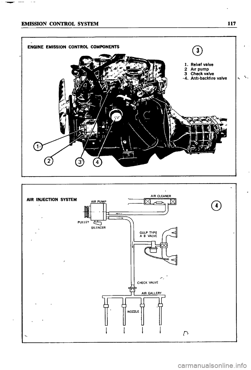
ENGINE
EMISSION
CONTROL
COMPONENTS
CD
1
Relief
valve
2
Air
pump
3
Check
valve
4
Anti
backfire
valve
AIR
INJECTION
SYSTEM
CD
SILENCER
CHECK
VALVE
NOZZLE
c
Page 127 of 252
122
CHAPTER
TEN
1
Start
the
engIne
and
bnng
It
up
to
normal
operatIng
temperature
2
Inspect
all
hoses
and
connectIons
for
leaks
and
detenoratIon
Shut
off
the
engme
Replace
any
defectIve
hoses
3
Remove
the
hose
attached
to
the
check
valve
4
VIsually
Inspect
the
posItIon
of
the
valve
plate
InsIde
the
valve
body
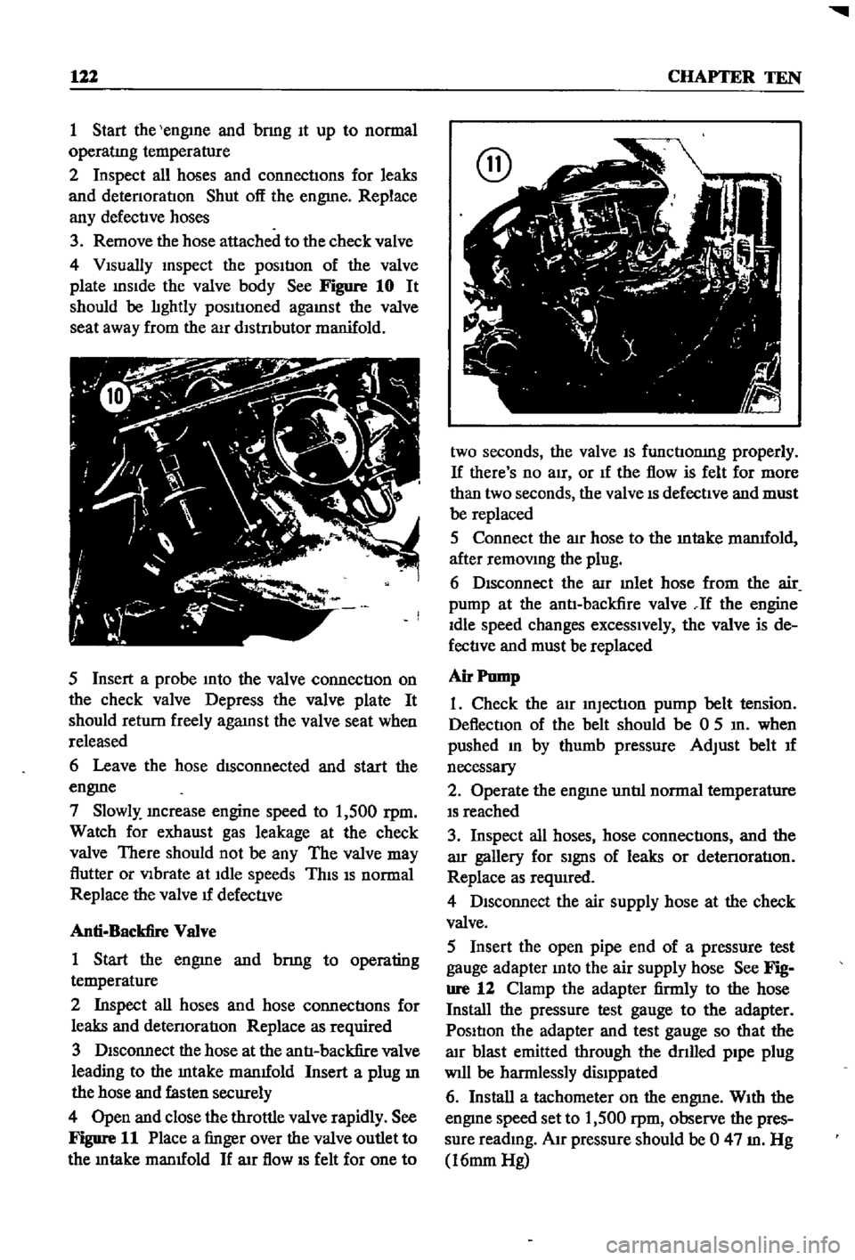
See
Figure
10
It
should
be
lIghtly
posItIoned
agaInst
the
valve
seat
away
from
the
aIr
dlstnbutor
manifold
5
Insert
a
probe
Into
the
valve
connectIon
on
the
check
valve
Depress
the
valve
plate
It
should
return
freely
agaInst
the
valve
seat
when
released
6
Leave
the
hose
dISconnected
and
start
the
engme
7
Slowly
Increase
engine
speed
to
1
500
rpm
Watch
for
exhaust
gas
leakage
at
the
check
valve
There
should
not
be
any
The
valve
may
flutter
or
VIbrate
at
Idle
speeds
ThIS
IS
normal
Replace
the
valve
u
defecuve
Anti
Backfire
Valve
1
Start
the
engme
and
bnng
to
operating
temperature
2
Inspect
all
hoses
and
hose
connectIons
for
leaks
and
detenoratIon
Replace
as
required
3
DIsconnect
the
hose
at
the
antI
backfire
valve
leading
to
the
Intake
manuold
Insert
a
plug
ill
the
hose
and
fasten
securely
4
Open
and
close
the
throttle
valve
rapidly
See
Figure
11
Place
a
finger
over
the
valve
outlet
to
the
m
take
manuold
If
arr
flow
IS
felt
for
one
to
two
seconds
the
valve
IS
functIonIng
properly
If
there
s
no
aIr
or
If
the
flow
is
felt
for
more
than
two
seconds
the
valve
IS
defectIve
and
must
be
replaced
5
Connect
the
alr
hose
to
the
mtake
manuold
after
remOVIng
the
plug
6
DIsconnect
the
aIr
mlet
hose
from
the
air
pump
at
the
antI
backfire
valve
If
the
engine
Idle
speed
changes
excessIvely
the
valve
is
de
fectIve
and
must
be
replaced
Air
Pump
1
Check
the
atr
InjectIon
pump
belt
tension
DeflectIon
of
the
belt
should
be
0
5
In
when
pushed
In
by
thumb
pressure
Adjust
belt
u
necessary
2
Operate
the
engme
untIl
normal
temperature
IS
reached
3
Inspect
all
hoses
hose
connectIons
and
the
arr
gallery
for
SIgnS
of
leaks
or
detenoratIon
Replace
as
required
4
DIsconnect
the
air
supply
hose
at
the
check
valve
5
Insert
the
open
pipe
end
of
a
pressure
test
gauge
adapter
Into
the
air
supply
hose
See
Fig
ure
12
Clamp
the
adapter
firmly
to
the
hose
Install
the
pressure
test
gauge
to
the
adapter
PosItIon
the
adapter
and
test
gauge
so
that
the
alr
blast
emitted
through
the
dnlled
pipe
plug
Will
be
harmlessly
dislppated
6
Install
a
tachometer
on
the
engme
WIth
the
engIne
speed
set
to
1
500
rpm
observe
the
pres
sure
readmg
AIr
pressure
should
be
0
47
m
Hg
16mm
Hg