1968 DATSUN 510 air condition
[x] Cancel search: air conditionPage 76 of 252
FUEL
SYSTEM
71
Dash
Pot
Adjustment
The
adjustment
of
the
dash
pot
IS
done
by
warmmg
up
the
engme
properly
and
checkIng
If
the
throttle
lever
touches
th
dash
pot
stem
as
the
engine
reaches
1
800
and
2
000
rpm
under
no
load
conditIons
Proper
contact
between
the
throttle
lever
and
the
dash
pot
stem
produces
a
normal
dash
pot
performance
Should
a
normal
mcrease
m
engme
speed
not
occur
adjust
the
dash
pot
as
follows
1
Loosen
the
dash
pot
locknuts
2
Rotate
the
dash
pot
nght
and
then
left
3
Adjust
the
dash
pot
so
that
the
throttle
lever
hIts
the
stem
between
1
800
and
2
000
rpm
4
Fasten
the
lock
nuts
securely
5
The
clearance
between
the
throttle
valve
and
the
throttle
chamber
wall
should
be
0
0709
m
0
8mm
or
10
degrees
In
throttle
valve
angle
MAJOR
CARBURETOR
SERVICE
PROCEDURES
A
carburetor
m
good
operatIng
condition
will
delIver
the
pr
per
gasolme
and
aIr
ratIos
for
all
engme
runnmg
speeds
A
gradual
declme
In
smoothness
response
and
power
Will
occur
as
the
carburetor
slIps
from
adjustment
and
Its
delI
cate
parts
become
dirty
and
worn
Overhaul
should
only
be
attempted
by
an
expenenced
mechanic
Accurate
calIbratIon
of
passages
and
dIS
charge
hole
reqUIre
that
extreme
care
be
taken
In
dISassembly
cleanmg
and
reassembly
Use
only
a
hIgh
grade
carburetor
cleaner
and
com
pressed
arr
to
clean
parts
and
passages
Never
use
wire
or
other
pOInted
Instruments
for
clean
ing
CalIbratIon
of
the
carburetor
will
be
af
fected
The
procedures
below
are
generally
true
for
all
models
As
an
aId
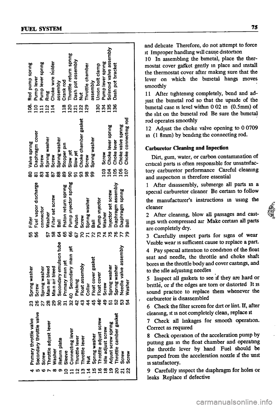
Figures
13
and
14
are
typIcal
examples
of
the
carburetors
used
Carburetor
Removal
1
Remove
the
au
cleaner
by
dIsconnectIng
all
hoses
attached
to
It
remoVmg
the
two
bolts
holdmg
the
aIr
cleaner
to
the
support
and
loos
enmg
the
band
bolt
at
the
base
of
the
aIr
cleaner
2
DIsconnect
fuellme
vacuum
Ime
and
choke
wire
u
eqUIpped
from
the
carburetor
3
Remove
the
throttle
lever
4
Remove
four
nuts
and
washers
holdmg
car
buretor
to
manIfold
5
Lift
carburetor
off
of
manuold
6
Remove
and
dIscard
carburetor
to
manuold
gasket
7
Place
carburetor
on
clean
workbench
Carburetor
Disassembly
1
The
maIn
Jets
slow
Jets
and
needle
valves
on
both
the
pnmary
and
secondary
systenIS
are
accessIble
from
outsIde
the
carburetor
Refer
to
FIgures
13
and
14
for
locatI
n
2
The
choke
chamber
can
be
detached
by
re
mOVIng
the
connectIng
rod
pump
connectIng
rod
return
sprmg
stop
pm
and
the
set
screws
I
that
hold
It
in
place
3
The
pnmary
and
secondary
emulSIon
tubes
can
be
disassembled
by
remOVIng
the
mam
air
bleeds
on
the
respectIve
SIdes
4
To
check
the
accelerator
pump
remove
the
cylInder
cover
Be
careful
not
to
lose
the
return
spnng
and
Inlet
valve
at
the
lower
part
of
the
pIston
durmg
dIsassembly
5
Detach
the
throttle
chamber
from
the
float
chamber
by
remOVIng
the
rod
lInkIng
the
dia
phragm
WIth
the
secondary
throttle
valve
and
the
four
screws
that
hold
It
However
It
IS
preferable
to
leave
the
throttle
valve
mtact
unless
absolutely
reqUired
If
It
IS
necessary
to
dlS
assemble
the
valve
It
should
be
Installed
so
that
the
secondary
throttle
valve
will
be
gap
free
OtherwIse
stable
Idle
and
good
slow
speed
performance
will
suffer
is
To
check
the
float
the
float
chamber
cover
must
be
removed
I
7
The
dIaphragm
IS
dIsassembled
by
removing
the
set
screws
holdmg
the
dIaphragm
chamber
cover
In
reassemblIng
the
diaphragm
be
careful
not
to
turn
the
edge
of
the
dIaphragm
up
8
In
dlsassemblmg
and
reassembling
the
mter
lockIng
lInks
take
care
so
that
each
lInkage
has
a
smooth
actIon
and
that
parts
are
not
forced
mto
pOSItIon
9
For
vehIcles
equipped
With
an
automatIc
choke
remove
the
brmetal
case
by
releasmg
the
set
screws
The
bimetal
1l
extremely
senSItIve
Page 80 of 252
FUEL
SYSTEM
75
s
E
u
m
c
DO
2
t
Eo
c
E
D
EEm
0
0
G
E
cac
cvu
cn
J
co
ucn
e
a
CVQ
CD
Q
c
E
C
u
0
J
oeQ
O
G
O
cQ
O
E
E
EE
g
0
E
E
Q
II
2
en
e
GJ
9
E
en
J
J
s
eJ
ctI
J
c
l
Joca
OmO
CZ
m
C
mO
NV
O
Nm
O
01
1
P
IC
lC
lC
lN
f
rr
r
tr
P
t
I
I
I
I
I
l
m
u
m
bOt
J
oCc
E
E
E
co
en
bel
3
J
ca
e
tt
tlu
3
j
31b031
31
c
G
Q
a
3
3
cuE
ca
0
0
0
0
O
Q
C
u
c3
0
I
q
COO
Ol
t
l
Q
O
ClOClOClOClOClOClOClOOlOlOlOlOl
2
DO
tlD
2
E
E
tl
cog
u
I
j
0
000
u
c
s
c
c
oooo
l
v
t
D
00000
tlD
tlD
3
f
c
0
CD
S
U
o
c
u
0
en
Q
en
Q
t
ee
o
B
c
e
cnbObO
ca
u
ca
ca
ga
C3
c
G
ccn2
ESft
EcnG
a
a
Joca
ca
J
ua
m
Jca
ca
u
ClO
ClO
CCClO
m
j
u
s
u
m
a
is
g
t
ii
E
l
1
b
en
1
t
t
iEc
c
m
cvCVQ
ccvcvCV
ca
E
co
C
C
E
caca
31
3l
m
ODO
00
3131
bel
bOcaca
caucca
UU
bO
CV
c3
cccoE
m
C
c
C
c
b
im
t
g
O
O
Z
d
M
ClOOlO
NNM
d
Ol
NM
d
NNNNNMMM
d
cvm
3
bO
u
5
cn
o
o
E
t
j
I
cn
c
z
lD
c
cn
tE
c
C
bOQ
Q
cn
C
ca
L
CQ
c
mCQcnuu
CQ
C1
Q
eC1
C1
C1
cnC1
i
E
EE
E
E
E
E
8
f
e
cn
a
c
e
e
i
e
Q
e
w8
z
d
ClOOlO
NM
ClOOlO
N
1
11
1
I
1
1
l
l
l
l
l
l
lC
lC
lC
l
and
delIcate
Therefore
do
not
attempt
to
force
It
Improper
handlmg
WIll
cau
e
dIstortIOn
10
In
assemblIng
the
bImetal
place
the
ther
mostat
cover
gaSket
gently
In
place
and
mstall
the
thermostat
cover
after
makmg
sure
that
the
lever
on
which
the
bImetal
hangs
moves
smoothly
11
After
ughtenmg
completely
bend
and
ad
Just
the
bImetal
rod
so
that
the
upSIde
of
the
bImetal
case
IS
level
withm
0
02
m
O
5mm
of
the
slIt
on
the
bImetal
rod
Be
sure
the
bImetal
rod
operates
smoothly
12
Adjust
the
choke
valve
opening
to
00709
m
1
8mm
by
bendIng
the
connecting
rod
Carburetor
Cleaning
and
Inpection
Dirt
gum
water
or
carbon
contammation
of
cntIcal
parts
IS
often
responsIble
for
unsatlsfac
tory
carburetor
performance
Careful
cleanmg
and
InspectIon
IS
therefore
essential
1
After
disassembly
submerge
all
parts
In
a
specIal
carburetor
cleaner
Be
certam
to
follow
the
mmufacrurer
s
instructions
In
usmg
the
cleaner
2
After
cleanmg
blow
all
passages
and
cast
mgs
With
compressed
aIr
Make
certam
all
parts
are
completely
dry
3
Carefully
mspect
parts
for
SIgnS
of
wear
VISIble
wear
IS
suffiCIent
cause
to
replace
a
part
4
Pay
speCIal
attentIon
to
condItIon
of
the
float
seat
and
needle
the
throttle
and
choke
shaft
bores
In
the
throttle
body
and
cover
castIngs
and
to
the
Idle
adjustIng
needles
5
Inspect
all
gaskets
to
see
IT
they
are
hard
or
bnttle
or
IT
the
edges
are
tom
or
dIstorted
It
IS
sound
practIce
to
replace
them
whenever
the
carburetor
is
dIsassembled
6
Check
the
filter
screen
for
dIrt
or
lint
If
after
cleanmg
It
IS
not
completely
clean
replace
It
7
Check
all
lInkages
for
smooth
operatIon
Correct
as
reqUIred
8
Check
operation
of
the
acceleration
pump
by
puttIng
gas
m
the
float
chamber
and
operatIng
the
throttle
lever
by
hand
Fuel
should
be
pumped
from
the
acceleration
nozzle
IT
the
unIt
IS
satlsfactory
9
Carefully
InSpect
the
dIaphragm
for
holes
or
leaks
Replace
IT
defective
il
Page 89 of 252
CHAPTER
EIGHT
COOLING
SYSTEM
The
coolIng
system
IS
of
the
closed
pressure
type
Coolant
flows
through
passages
In
the
cyl
mder
head
and
block
and
is
cooled
by
the
radIator
water
pump
and
thermostat
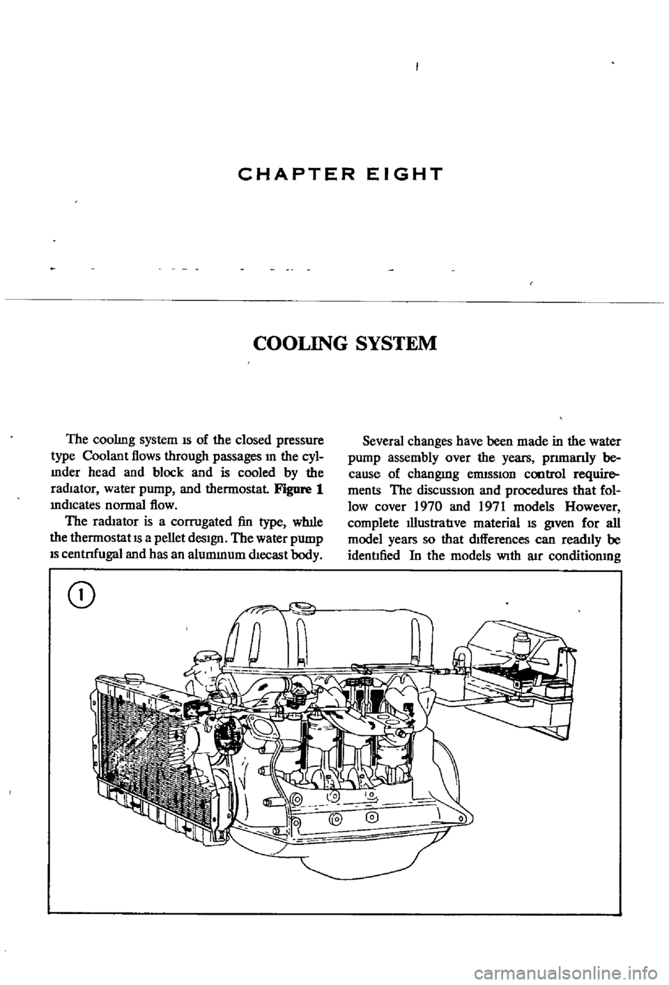
Figure
1
mdlcates
normal
flow
The
radIator
is
a
corrugated
fin
type
wh1le
the
thermostat
IS
a
pellet
desIgn
The
water
pump
IS
centnfugal
and
has
an
alummum
dlecast
body
CD
Several
changes
have
been
made
in
the
water
pump
assembly
over
the
years
pnmanly
be
cause
of
changmg
ennSSlon
cootrol
require
ments
The
diSCUSSIOn
and
procedures
that
fol
low
cover
1970
and
1971
models
However
complete
IllustratIve
material
IS
given
for
all
model
years
so
that
dIfferences
can
readIly
be
identIfied
In
the
models
With
aIr
conditionmg
Page 118 of 252
ENGINE
ELECI
RICAL
SYSTEM
113
i
Normal
plug
appearance
noted
by
the
brown
to
graYlsll
lan
depOSits
and
slight
eleclrode
wear
This
plug
indicates
the
correct
plug
heal
range
and
proper
air
fuel
ratio
jI
Jo
t
Ql
i
Carbon
fouhng
distinguished
by
dry
fluffy
black
carbon
depOSits
which
may
be
caused
by
an
over
rich
alr
lue
mixture
excessive
hand
choking
clogged
air
filler
or
excessl
e
Idling
t
I
j
if
r
l
1
tfc
ji
0
1
fouling
indicated
by
wet
o
ly
depOSits
caused
by
011
pumping
past
worn
rings
or
down
the
Intake
valve
gUIdes
A
hotter
plug
temporanly
reduces
011
depOSits
but
a
plug
that
IS
too
hot
leads
to
pre
Ignition
end
possible
engine
damage
@
Red
brown
yellow
and
white
coatings
caused
by
luel
and
011
addltl
es
These
depOSits
are
not
harm
ful
If
they
remain
In
a
powdery
lorm
pr
11
L
J
J
S
C
ShinY
yellow
glaze
on
Insulalor
cone
IS
caused
when
the
powdery
depOSits
from
fuel
and
011
addltl
es
melt
Melting
occurs
during
hard
acceleration
alter
prolonged
Idling
This
glaze
conducts
electnclty
and
shorts
out
the
plug
e
1
A
I
A
I
7
Overheated
plug
indIcated
by
burned
or
blistered
Insulator
tiP
and
badly
worn
electrodes
ThiS
condl
J
tlon
may
be
caused
by
pre
Ignition
cooling
system
defects
lean
alr
luel
ratiOS
low
octane
luel
or
o
er
advanced
Ignition
timing
Spark
plUI
condition
photos
courtesy
of
AC
SPIr1l
Plug
Olv
s
on
Gene
MolDrs
Corporlllon
Page 119 of 252
CHAPTER
TEN
EMISSION
CONTROL
SYSTEM
ThIs
chapter
covers
emission
control
and
exhaust
systems
The
emission
devices
used
in
clude
crankcase
ermssion
controls
an
exhaust
ermssion
system
and
evaporative
emission
con
trols
EXHAUST
EMISSION
CONTROL
SYSTEM
Two
methods
of
exhaust
emission
control
are
used
on
the
Datsun
One
is
an
aIr
injection
system
the
other
consists
of
engine
modifica
tIons
Datsuns
were
equipped
With
the
air
injec
tIon
system
only
through
1970
SInce
then
all
models
have
combined
aIr
mjection
with
engine
modIficatIons
EmisSIon
servicing
IS
complex
and
should
be
left
to
qualIfied
professionals
Figure
1
Illustrates
the
system
used
through
model
year
1969
Figure
2
IS
the
system
used
after
1970
Figures
3
through
7
offer
detaIls
of
various
emission
components
Maintenance
and
Testing
Penodlc
mspection
and
service
should
be
done
every
12
months
or
12
000
miles
The
engine
must
be
in
good
working
order
to
main
tain
a
low
level
of
harmful
emissions
There
fore
perform
a
general
tune
up
as
spec1fied
in
Chapter
Four
before
followmg
the
procedures
below
CRANKCASE
EMISSION
CONTROL
SYSTEM
The
crankcase
emission
control
system
is
shown
in
FlgDre
8
It
IS
a
closed
system
that
pre
vents
crankcase
gases
from
escaping
to
the
at
mosphere
Blowby
gases
are
dIrected
to
the
intake
manifold
through
the
ventilation
control
valve
Normally
capacity
of
the
valve
is
suffi
cient
to
handle
the
blowby
gas
plus
a
small
amount
of
ventIlating
air
drawn
from
the
air
cleaner
through
a
tube
leading
to
the
crankcase
Under
fun
throttle
condItIons
manifold
vacuum
is
Insufficient
to
draw
the
blowby
through
the
valve
When
this
happens
b10wby
flows
through
the
system
In
the
reverse
dIrection
General
1
Start
the
engine
and
bring
up
to
operating
temperature
2
Check
hoses
and
hose
connections
for
leaks
3
Examine
the
hoses
for
signs
of
cracks
or
de
terioraoon
Replace
as
required
Crankcase
Ventilation
Control
Valve
1
Start
the
engme
2
Remove
the
ventIlator
hose
from
the
crank
case
ventilatIon
control
valve
A
htssmg
nOISe
Page 133 of 252
128
CHAPTER
ELEVEN
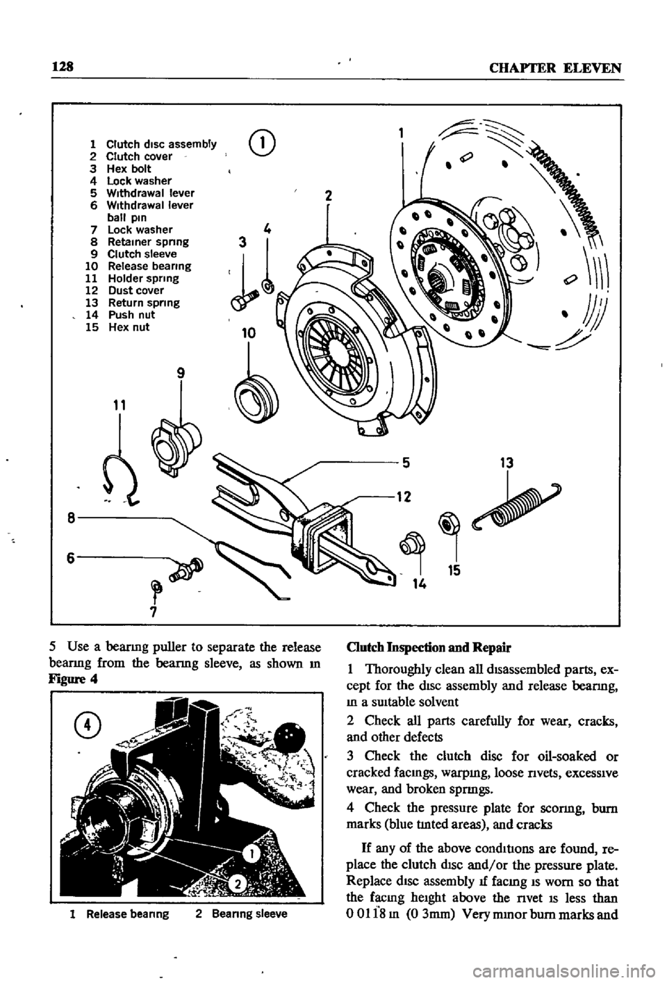
1
Clutch
disc
assembly
2
Clutch
cover
3
Hex
bolt
4
Lock
washer
5
Withdrawal
lever
6
Withdrawal
lever
ball
pin
7
Lock
washer
8
Retainer
spnng
9
Clutch
sleeve
10
Release
bearing
11
Holder
spring
12
Dust
cover
13
Return
spring
14
Push
nut
15
Hex
nut
CD
9
11
8
6
7
1
Release
beanng
2
Beanng
sleeve
2
5
13
12
15
14
Clutch
Inspection
and
Repair
1
Thoroughly
clean
all
dISassembled
parts
ex
cept
for
the
dISc
assembly
and
release
bearmg
In
a
SUItable
solvent
2
Check
all
parts
carefully
for
wear
cracks
and
other
defects
3
Check
the
clutch
disc
for
oil
soaked
or
cracked
faCIngs
warpmg
loose
nvets
exceSSIve
wear
and
broken
spnngs
4
Check
the
pressure
plate
for
sconng
bum
marks
blue
tlnted
areas
and
cracks
If
any
of
the
above
condItIons
are
found
re
place
the
clutch
dISC
and
or
the
pressure
plate
Replace
dISC
assembly
1f
facmg
IS
worn
so
that
the
facmg
heIght
above
the
nvet
IS
less
than
00118m
03mm
Very
mmor
bum
marks
and
Page 146 of 252
CLUTCH
TRANSMISSION
AND
DRlVESHAFI
141
22
Remove
the
thrust
washer
and
mam
shaft
1st
speed
gear
complete
With
needle
roller
bear
mg
Be
careful
not
to
lose
the
small
steel
ball
which
locates
the
thrust
washer
Remove
main
shaft
1st
gear
bushmg
23
Remove
the
mam
shaft
2nd
speed
gear
and
needle
roller
bearmg
24
To
dISassemble
synchronizer
assembly
re
move
sprmgs
from
both
ends
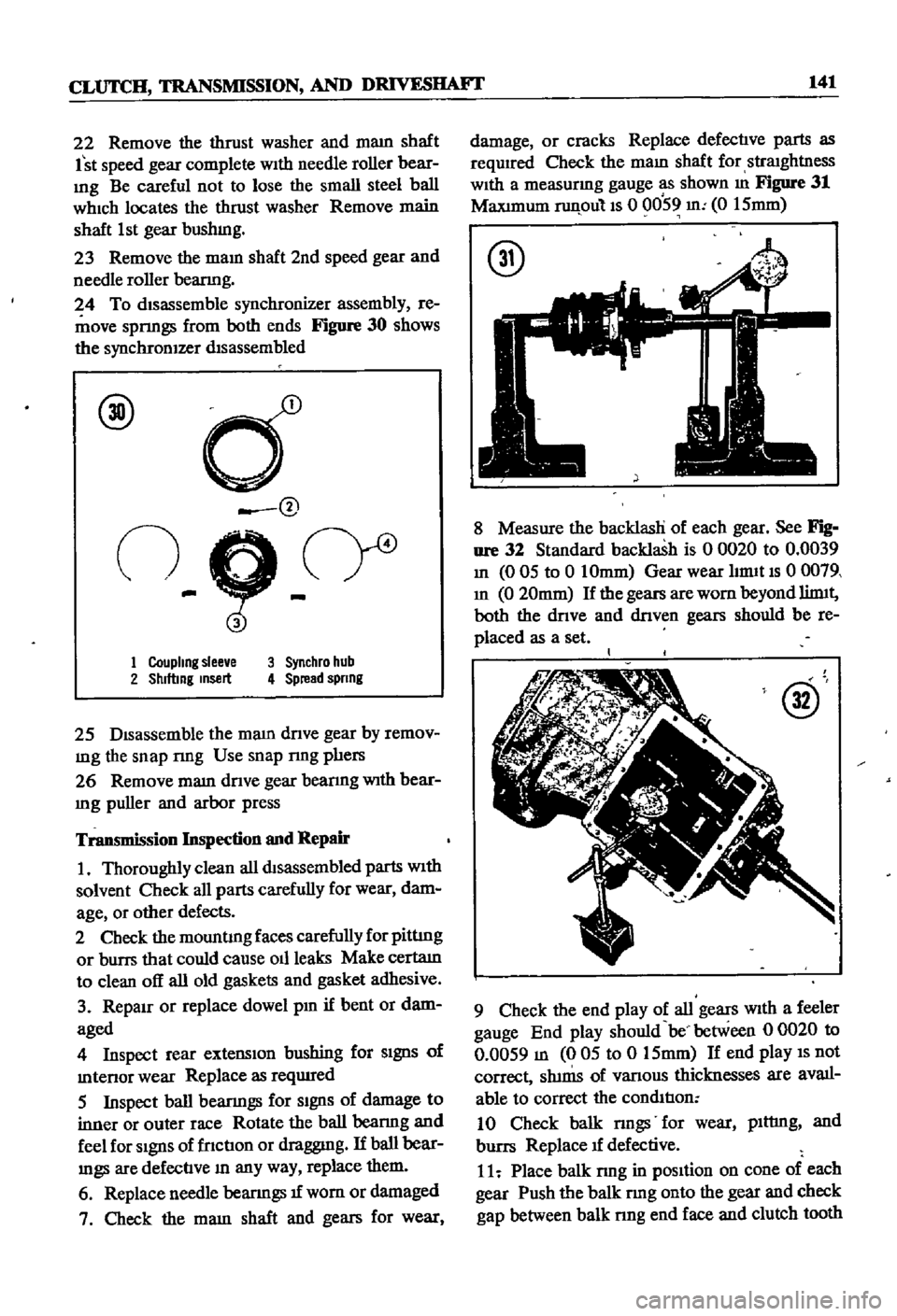
Figure
30
shows
the
synchronIZer
dIsassembled
@
d
@
n
9
cr
1
Coupling
slee
e
3
Synchro
hub
2
Shlftmg
msert
4
Spread
spnng
25
DIsassemble
the
mam
dnve
gear
by
remov
mg
the
snap
nng
Use
snap
nng
phers
26
Remove
mam
dnve
gear
bearmg
With
bear
Ing
puller
and
arbor
press
Transmission
Inspection
and
Repair
1
Thoroughly
clean
all
dtsassembled
parts
With
solvent
Check
all
parts
carefully
for
wear
dam
age
or
other
defects
2
Check
the
mountIng
faces
carefully
for
pittIng
or
burrs
that
could
cause
011
leaks
Make
certatn
to
clean
off
all
old
gaskets
and
gasket
adhesive
3
RepaIr
or
replace
dowel
pm
if
bent
or
dam
aged
4
Inspect
rear
extensIon
bushing
for
SIgnS
of
mtenor
wear
Replace
as
reqUIred
5
Inspect
ball
bearmgs
for
SIgnS
of
damage
to
inner
or
outer
race
Rotate
the
ball
bearmg
and
feel
for
SIgnS
of
fnctIon
or
draggmg
If
ball
bear
mgs
are
defectIve
In
any
way
replace
them
6
Replace
needle
bearIngs
1f
wom
or
damaged
7
Check
the
mam
shaft
and
gears
for
wear
damage
or
cracks
Replace
defectIve
parts
as
required
Check
the
maIn
shaft
for
straIghtness
WIth
a
measurmg
gauge
as
shown
m
Figure
31
MaxImum
runpulls
0
0059
m
0
15mm
@
8
Measure
the
backlasH
of
each
gear
See
Fig
nre
32
Standard
backlash
is
0
0020
to
0
0039
In
0
05
to
0
10mm
Gear
wear
hrmt
IS
0
0079
In
0
20mm
If
the
gears
are
worn
beyond
limtt
both
the
dnve
and
dnven
gears
should
be
re
placed
as
a
set
@
9
Check
the
end
play
of
all
gears
WIth
a
feeler
gauge
End
play
should
be
between
0
0020
to
0
0059
m
005
to
0
15mm
If
end
play
IS
not
correct
Sh1nIS
of
vanous
thicknesses
are
avail
able
to
correct
the
condItIon
10
Check
balk
nngs
for
wear
plttmg
and
burrs
Replace
1f
defective
11
Place
balk
rmg
in
pOSItion
on
cone
of
each
gear
Push
the
balk
rmg
onto
the
gear
and
check
gap
between
balk
nng
end
face
and
clutch
tooth
Page 152 of 252
CLUTCH
TRANSMISSION
AND
DRIVESHAFI
147
SERVICE
DATA
AND
SPECIFICATIONS
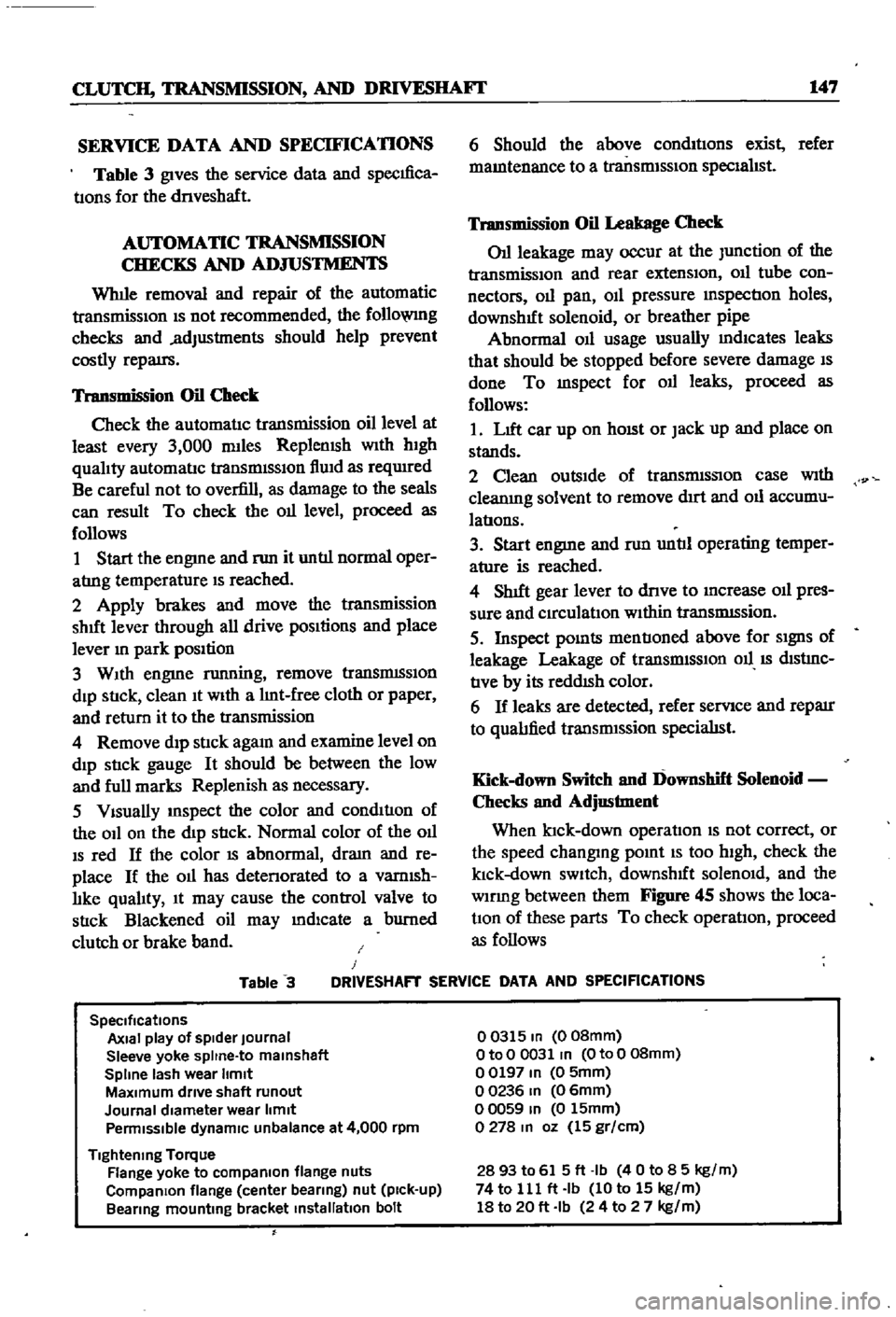
Table
3
gives
the
service
data
and
specIfica
tIons
for
the
dnveshaft
AUTOMATIC
TRANSMISSION
CHECKS
AND
ADJUSTMENTS
Whlle
removal
and
repair
of
the
automatic
transmisSIOn
IS
not
recommended
the
follo
VlIlg
checks
and
adjustments
should
help
prevent
costly
repatrs
Transmission
Oil
Check
Check
the
automatIc
transmission
oil
level
at
least
every
3
000
mlles
Replemsh
With
hIgh
qualIty
automatIc
transmISSIon
flUId
as
reqUIred
Be
careful
not
to
overfill
as
damage
to
the
seals
can
result
To
check
the
011
level
proceed
as
follows
1
Start
the
engme
and
nm
it
untIl
normal
oper
atrng
temperature
IS
reached
2
Apply
brakes
and
move
the
transmission
shut
lever
through
all
drive
pOSItions
and
place
lever
In
park
position
3
WIth
engme
running
remove
tranSmISSIon
dIp
StIck
clean
It
WIth
a
lInt
free
cloth
or
paper
and
return
it
to
the
transmission
4
Remove
dIp
stIck
agam
and
examine
level
on
dIp
stIck
gauge
It
should
be
between
the
low
and
full
marks
Replenish
as
necessary
5
VIsually
InSpect
the
color
and
condItIon
of
the
OIl
on
the
dIp
stIck
Normal
color
of
the
OIl
IS
red
If
the
color
IS
abnormal
dram
and
re
place
If
the
011
has
detenorated
to
a
vamlsh
lIke
qualIty
It
may
cause
the
control
valve
to
stIck
Blackened
oil
may
mdlcate
a
burned
clutch
or
brake
band
6
Should
the
above
condItIons
exist
refer
mamtenance
to
a
transmISSIon
specIalIst
Transmission
Oil
Leakage
Check
011
leakage
may
occur
at
the
Junction
of
the
transmissIon
and
rear
extensIon
011
tube
con
nectors
011
pan
OIl
pressure
mspectIon
holes
downshIft
solenoid
or
breather
pipe
Abnormal
OIl
usage
usually
mdlcates
leaks
that
should
be
stopped
before
severe
damage
IS
done
To
mspect
for
011
leaks
proceed
as
follows
1
LIft
car
up
on
hOISt
or
Jack
up
and
place
on
stands
2
Clean
outsIde
of
transmISSIon
case
With
cleanIng
solvent
to
remove
dIrt
and
011
accumu
latIons
3
Start
engme
and
nm
untIl
operating
temper
ature
is
reached
4
ShIft
gear
lever
to
dnve
to
Increase
011
pres
sure
and
CIrculatIon
WIthin
tranSmISsion
5
Inspect
pOInts
mentIoned
above
for
SIgnS
of
leakage
Leakage
of
transrmSSIOn
011
IS
dIStrnC
tIve
by
its
reddISh
color
6
If
leaks
are
detected
refer
servIce
and
reparr
to
qualIfied
transrmssion
specialISt
Kick
down
Switch
and
Downshift
Solenoid
Checks
and
Adjustment
When
ktck
down
operatIon
IS
not
correct
or
the
speed
changmg
pomt
IS
too
high
check
the
klck
down
SWItch
downshIft
solenOId
and
the
wlDng
between
them
Figure
45
shows
the
loca
tIOn
of
these
parts
To
check
operatIon
proceed
as
follows
Table
3
J
DRIVESHAFT
SERVICE
DATA
AND
SPECIFICATIONS
SpeCifications
Axial
play
of
spider
Journal
Sleeve
yoke
spltne
to
malnshaft
Spline
lash
wear
Itmlt
MaXimum
drive
shaft
runout
Journal
diameter
wear
limit
Penmlsslble
dynamiC
unbalance
at
4
000
rpm
Tightening
Torque
Flange
yoke
to
compaRlon
flange
nuts
CompaRlon
flange
center
bearing
nut
pick
up
Bearing
mounting
bracket
installation
bolt
00315
In
008mm
OtoO
0031
In
OtoO
08mm
00197
In
0
5mm
00236
In
06mm
00059
In
0
15mm
0278
In
oz
15
gr
cm
2893
to
615ft
Ib
40
to
8
5
kg
m
74
to
111
ft
Ib
10
to
15
kg
m
18
to
20
ft
Ib
24
to
2
7
kg
m