1968 DATSUN 510 air condition
[x] Cancel search: air conditionPage 159 of 252
154
CHAPTER
tWELVE
move
two
nuts
attachmg
dtfferenual
suspension
member
to
the
body
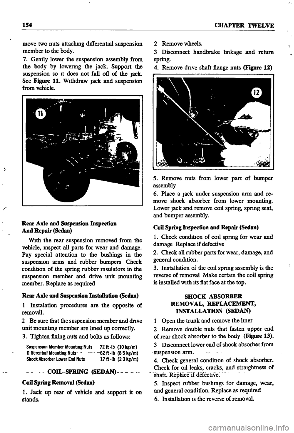
7
Gently
lower
the
suspension
assembly
from
the
body
by
10wermg
the
jack
Support
the
suspension
so
It
does
not
fall
off
of
the
Jack
See
Figure
11
WIthdraw
Jack
and
suspension
from
vehicle
Rear
Axle
and
Suspension
Inspedion
And
Repair
Sedan
WIth
the
rear
suspension
removed
from
the
vehicle
InSpect
all
parts
for
wear
and
damage
Pay
special
attention
to
the
bushings
in
the
suspensIon
arms
and
robber
bumpers
Check
conditIon
of
the
spring
robber
msulators
in
the
suspensIOn
member
and
drive
unit
mounting
member
Replace
as
required
Rear
Axle
and
Suspension
InstaDation
Sedan
1
Instalation
procedures
are
the
opposite
of
removal
2
Be
sure
that
the
suspension
member
and
dnve
unit
mountmg
member
are
med
up
correctly
3
Tighten
fixing
nuts
and
bolts
as
follows
Suspension
Member
Mounting
Nuts
72
It
Ib
10
kg
m
Dlfferenbal
Mounting
Nuls
62
It
Ib
85
kg
m
Shock
Absorber
Lower
End
Nuts
17
It
Ib
23
kg
m
COIL
SPRING
SEDAN
Coil
Spring
Removal
Sedan
1
Jack
up
rear
of
vehicle
and
support
it
on
stands
2
Remove
wheels
3
Disconnect
handbrake
mkage
and
retl1rn
spring
4
Remove
dnve
shaft
flange
nuts
Figure
12
5
Remove
nuts
from
lower
part
of
bumper
assembly
6
Place
a
Jack
under
suspension
arm
and
re
move
shock
absorber
from
lower
mounting
Lower
Jack
and
remove
coll
spring
spnng
seat
and
bumper
assembly
Coil
Spring
Inspection
and
Repair
Sedan
1
Check
condItIon
of
coll
sprmg
for
wear
and
damage
Replace
if
defective
2
Check
all
robber
parts
for
wear
damage
and
general
condItion
3
Installation
of
the
coll
spnng
assembly
is
the
reverse
of
removal
Make
certam
the
coil
spring
is
installed
With
Its
flat
face
at
the
top
SHOCK
ABSORBER
REMOVAL
REPLACEMENT
INSTALLATION
SEDAN
1
Open
the
trunk
and
remove
the
mer
2
Remove
double
nuts
that
fasten
upper
end
of
rear
shock
absorber
to
the
body
Figure
13
3
DIsconnect
lower
end
of
shock
absorber
from
suspensIon
arm
4
Check
general
conditIon
of
shock
absorber
Check
for
011
leaks
cracks
and
straIghtness
of
shaft
Replaceif
defectIve
5
Inspect
robber
bushmgs
for
damage
wear
and
general
condition
Replace
as
required
6
InstallatIon
IS
the
reverse
of
removal
Page 160 of 252
DIFFERENTIAL
REAR
AXLE
AND
REAR
SUSPENSION
155
i
I
I
I
REAR
SUSPENSION
ARM
SEDAN
Rear
Suspension
Arm
Removal
Sedan
1
Jack
up
the
rear
of
the
vehIcle
and
support
It
on
stands
2
Remove
wheel
and
brake
drum
3
DIsconnect
dnve
shaft
from
axle
shaft
4
Remove
handbrake
cable
from
lever
attached
to
wheel
cylInder
5
Plug
brake
tube
to
prevent
loss
of
brake
flwd
6
Remove
wheel
beanng
lock
nut
rear
axle
shaft
wheel
beanngs
and
OIl
seal
Remove
rear
brake
assembly
from
suspensIOn
arm
7
Place
Jack
under
suspenSIon
arm
remove
shock
absorber
from
lower
bracket
lower
Jack
gradually
remove
coll
spnng
spnng
seat
and
bumper
assembly
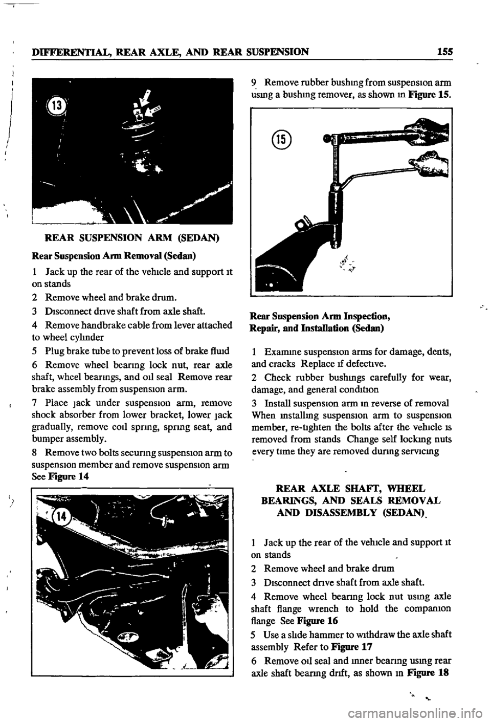
8
Remove
two
bolts
secunng
suspensIOn
arm
to
suspensIOn
member
and
remove
suspensIOn
arm
See
Figure
14
9
Remove
rubber
bushmg
from
suspensIon
arm
usmg
a
bushmg
remover
as
shown
In
Figure
15
@
Rear
SllSpension
Arm
Inspection
Repair
and
Installation
Sedan
1
Examme
suspensIOn
arms
for
damage
dents
and
cracks
Replace
tf
defectIve
2
Check
rubber
bushmgs
carefully
for
wear
damage
and
general
condItIon
3
Install
suspensIOn
arm
m
reverse
of
removal
When
Installmg
suspensIOn
arm
to
suspensIOn
member
re
tIghten
the
bolts
after
the
vehIcle
IS
removed
from
stands
Change
self
lockmg
nuts
every
tIme
they
are
removed
dunng
semcmg
REAR
AXLE
SHAFf
WHEEL
BEARINGS
AND
SEALS
REMOVAL
AND
DISASSEMBLY
SEDAN
1
Jack
up
the
rear
of
the
vehIcle
and
support
It
on
stands
2
Remove
wheel
and
brake
drum
3
DIsconnect
dnve
shaft
from
axle
shaft
4
Remove
wheel
bearmg
lock
nut
usmg
axle
shaft
flange
wrench
to
hold
the
companIOn
flange
See
Figure
16
5
Use
a
slIde
hammer
to
Withdraw
the
axle
shaft
assembly
Refer
to
Figure
17
6
Remove
011
seal
and
Inner
bearmg
usmg
rear
axle
shaft
bearmg
dnft
as
shown
In
Figure
18
Page 172 of 252

DIFFERENTIAL
REAR
AXLE
AND
REAR
SUSPENSION
167
REAR
SUSPENSION
pICK
UP
Rear
Suspension
Inspection
nnd
Repair
Pick
up
1
Check
spnngs
for
cracks
breaks
and
general
conditIon
Replace
as
reqwred
If
a
spnng
on
one
Side
IS
replaced
also
replace
the
other
one
2
Check
U
bolts
for
bends
stripped
threads
and
general
conditIon
Replace
as
reqUIred
3
Check
rubber
bumpers
and
bushings
for
cracks
wear
and
general
condll1on
Replace
if
defecl1ve
4
Check
shock
absorbers
for
leaks
or
other
damage
Replace
as
required
Rear
Suspension
Installation
Pick
up
1
Replace
the
rear
suspension
components
m
the
reverse
order
of
removal
2
When
msta11mg
rubber
bushmgs
coat
them
hghtly
With
a
soap
solution
3
Torque
parts
as
follows
Shackle
Pin
Spnng
Pm
U
Bolt
Secunng
Nut
Shock
Absorber
Upper
Nut
Shock
Absorber
Lower
Nut
Dnve
Shalt
Secunng
Bolt
83
to
94
It
Ib
11
5
to
13
kg
m
83
to
94
It
Ib
115
to
13
kg
m
61
to
72
ItAb
85
to
10
kg
m
26
to
31
It
Ib
36
t04
3
kg
m
10
to
12
ft
Ib
1
4
to
1
6
kg
m
18
to
22
ft
Ib
25
to
30
kg
m
NOTE
Retighten
bolts
and
nuts
that
hold
bushmgs
after
vehicle
has
been
removed
from
Jack
and
stands
Page 177 of 252
17
CHAPTER
THIRTEEN
CD
7
Remove
bearing
collar
and
extract
the
outer
beanng
cage
8
Use
a
screwdriver
to
remove
front
hub
grease
seal
and
imIer
bearmg
cage
9
Use
a
dnft
to
punch
out
the
outer
and
mner
race
of
the
outer
bearmgs
Punch
out
imIer
bearing
10
Detach
rotor
from
wheel
hub
as
shown
in
FJgUre
7
@
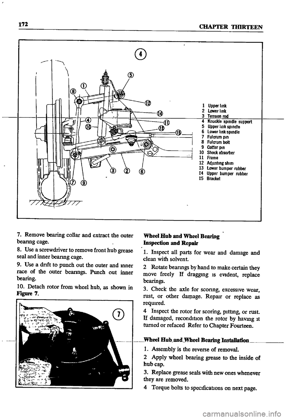
1
Upper
Imk
2
Lower
Imk
3
TenSIOn
rod
4
Knuckle
spindle
support
5
Upper
link
sptndle
6
lower
link
spmdle
7
Fulcrum
pm
8
Fulcrum
bolt
9
Cotter
ptn
10
Shock
absorber
11
Frame
12
AdJustmg
shim
13
Lower
bumper
rubber
14
Upper
bumper
rubber
15
Bracket
Wheel
Hub
nnd
Wheel
Bearing
Inspection
nnd
Repair
1
Inspect
all
parts
for
wear
and
damage
and
clean
with
solvent
2
Rotate
bearmgs
by
hand
to
make
certain
they
move
freely
If
draggnIg
IS
eVident
replace
bearings
3
Check
the
axle
for
sconng
excessive
wear
rust
or
other
daJP
age
Reparr
or
replace
as
requIred
4
Inspect
the
rotor
for
scoring
pIttIng
or
rust
If
damaged
reconditIon
the
rotor
by
haVlDg
It
tumed
or
refaced
Refer
to
Chapter
Fourteen
Wheel
Hub
nnd
Wheel
Bearing
Installation
1
Assembly
is
the
reverse
of
removal
2
Apply
wheel
bearing
grease
to
the
inside
of
hub
cap
3
Replace
grease
seals
with
new
ones
whenever
they
are
removed
4
Torque
bolts
to
specIficatIons
on
next
page
Page 184 of 252
FRONT
AXLE
FRONT
SUSPENSION
AND
STEERING
179
17
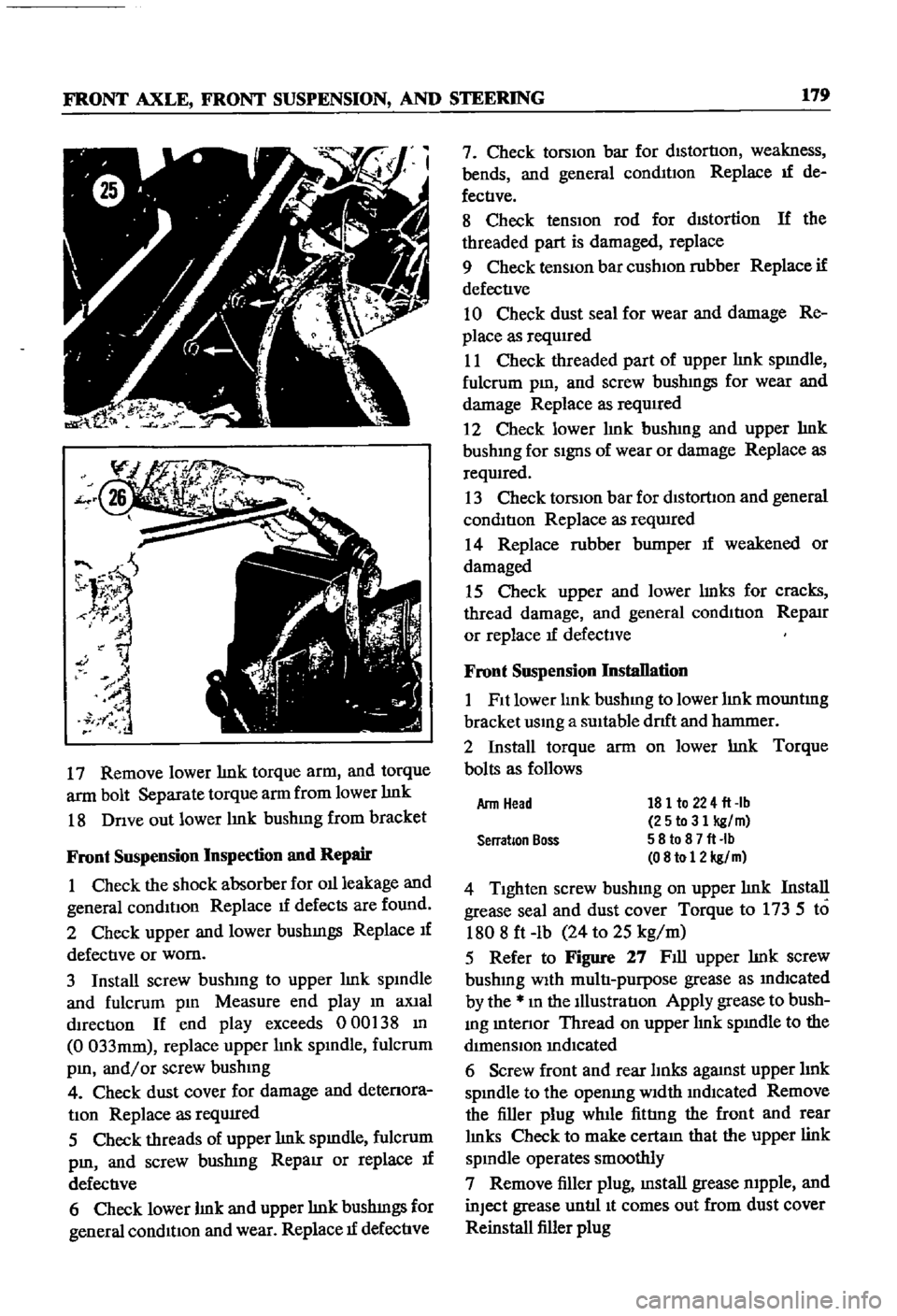
Remove
lower
lmk
torque
arm
and
torque
arm
bolt
Separate
torque
arm
from
lower
lmk
18
Dnve
out
lower
lmk
bushmg
from
bracket
Front
Suspension
Inspection
and
Repair
1
Check
the
shock
absorber
for
011
leakage
and
general
conditIon
Replace
1f
defects
are
found
2
Check
upper
and
lower
bushmgs
Replace
If
defective
or
worn
3
Install
screw
bushmg
to
upper
lmk
spmdle
and
fulcrum
pm
Measure
end
play
m
aXial
dIrection
If
end
play
exceeds
000
38
m
0
033mm
replace
upper
lmk
spmdle
fulcrum
pm
and
or
screw
bushmg
4
Check
dust
cover
for
damage
and
detenora
tIon
Replace
as
reqUIred
5
Check
threads
of
upper
lmk
spmdle
fulcrum
pm
and
screw
bushmg
RepaIr
or
replace
If
defective
6
Check
lower
lmk
and
upper
lmk
bushmgs
for
general
condition
and
wear
Replace
1f
defective
7
Check
torsion
bar
for
distortion
weakness
bends
and
general
conmtIon
Replace
If
de
fectIve
8
Check
tensIOn
rod
for
dIStortion
If
the
threaded
part
is
damaged
replace
9
Check
tenSiOn
bar
cushIOn
rubber
Replace
if
defective
10
Check
dust
seal
for
wear
and
damage
Re
place
as
requIred
11
Check
threaded
part
of
upper
lmk
spmdle
fulcrum
pm
and
screw
bushmgs
for
wear
and
damage
Replace
as
required
2
Check
lower
hnk
bushmg
and
upper
hnk
bushmg
for
SignS
of
wear
or
damage
Replace
as
reqwred
13
Check
torsIOn
bar
for
dlstorllon
and
general
condition
Replace
as
reqwred
14
Replace
rubber
bumper
If
weakened
or
damaged
15
Check
upper
and
lower
lmks
for
cracks
thread
damage
and
general
condition
RepaIr
or
replace
If
defectIve
Front
Suspension
Installation
1
Fit
lower
lmk
bushmg
to
lower
lmk
mountmg
bracket
usmg
a
SUItable
drlft
and
hanmIer
2
Install
torque
arm
on
lower
lmk
Torque
bolts
as
follows
181
to
224
fl
lb
25to31
kg
m
58
to
8
7
fl
Ib
08
to
12
kg
m
4
Tighten
screw
bushmg
on
upper
lmk
Install
grease
seal
and
dust
cover
Torque
to
173
5
to
1808
ft
lb
24
to
25
kg
m
5
Refer
to
Figure
27
Fill
upper
lmk
screw
bushmg
With
multi
purpose
grease
as
mdlcated
by
the
m
the
Illustration
Apply
grease
to
bush
mg
mtenor
Thread
on
upper
lmk
spmdle
to
the
dimenSIOn
mdIcated
6
Screw
front
and
rear
lInks
agaJnst
upper
hnk
spmdle
to
the
openmg
Width
mdlcated
Remove
the
filler
plug
while
fittIng
the
front
and
rear
lmks
Check
to
make
cectam
that
the
upper
link
spmdle
operates
smoothly
7
Remove
filler
plug
mstall
grease
mpple
and
inJect
grease
untIl
It
comes
out
from
dust
cover
Reinstall
filler
plug
Arm
Head
Serration
Boss
Page 196 of 252
BRAKES
191
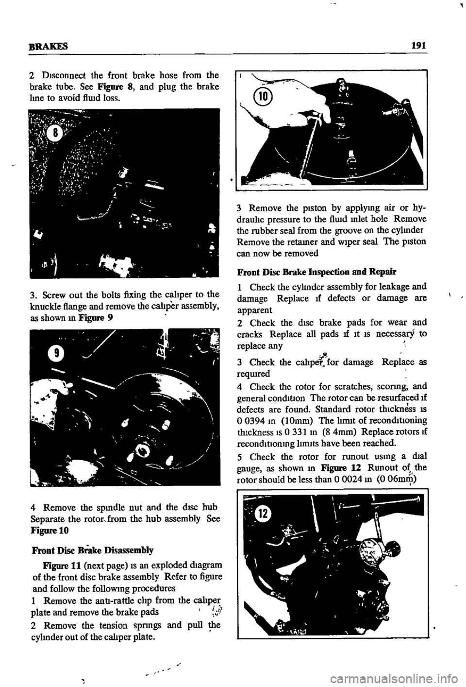
2
Disconnect
the
front
brake
hose
from
the
brake
tube
See
Figure
8
and
plug
the
brake
hne
to
avoid
flwd
loss
3
Screw
out
the
bolts
fixing
the
calJper
to
the
knuckle
flange
and
remove
the
calJper
assembly
as
shown
m
Figure
9
4
Remove
the
spmdle
nut
and
the
dISC
hub
Separate
the
rotor
from
the
hub
assembly
See
Figure
10
Front
Disc
Brake
Disassembly
Figure
11
next
page
IS
an
exploded
diagram
of
the
front
disc
brake
assembly
Refer
to
figure
and
follow
the
followmg
procedures
I
Remove
the
antI
rattle
clip
from
the
calJper
plate
and
remove
the
brake
pads
4
2
Remove
the
tension
spnngs
and
pull
the
cyhnder
out
of
the
caliper
plate
3
Remove
the
piston
by
applymg
air
or
hy
draulJc
pressure
to
the
flwd
mlet
hole
Remove
the
rubber
seal
from
the
groove
on
the
cyhnder
Remove
the
retamer
and
Wiper
seal
The
pISton
can
now
be
removed
Front
Disc
Brake
Inspection
and
Repair
I
Check
the
cyhnder
assembly
for
leakage
and
damage
Replace
If
defects
or
damage
are
apparent
2
Check
the
disc
brake
pads
for
wear
and
cracks
Replace
all
pads
If
It
IS
necessary
to
replace
any
fi
3
Check
the
caliper
for
damage
Replace
as
reqUIred
4
Check
the
rotor
for
scratches
sconng
and
general
conditIon
The
rotor
can
be
resurfaced
If
defects
are
found
Standard
rotor
thiCknesS
IS
o
0394
m
IOmm
The
hm1t
of
reconditIOning
thickness
IS
0
331
m
8
4mm
Replace
rotors
If
recondltIomng
limits
have
been
reached
5
Check
the
rotor
for
TWlout
usmg
a
dial
gauge
as
shown
m
Figure
12
Rnnout
ot
the
rotor
should
be
less
than
0
0024
m
0
06DlIll
Page 198 of 252
BRAKES
193
Front
Disc
Brake
Piston
Seal
Replacement
If
oil
leakage
is
detected
around
the
piston
seal
It
should
be
replaced
as
follows
I
Rinse
the
cyhnder
bore
With
brake
flwd
In
sert
new
seal
into
the
groove
taking
care
not
to
damage
It
Attach
the
wiper
seal
Lubricate
cylinder
bore
lightly
With
brake
fluid
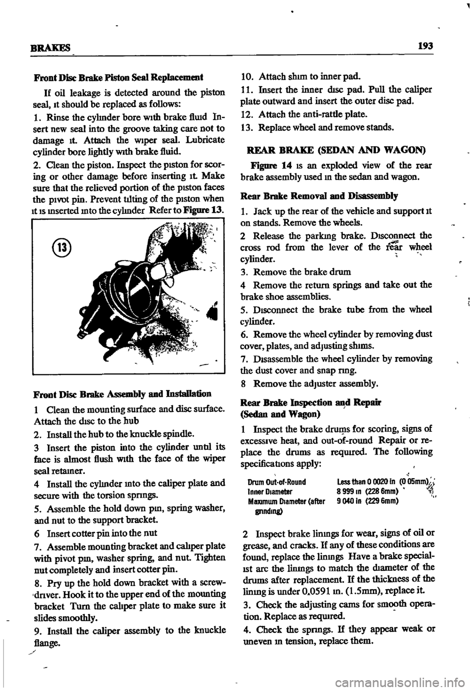
2
Clean
the
piston
Inspect
the
pISton
for
scor
ing
or
other
damage
before
inserting
It
Make
sure
that
the
relieved
portion
of
the
pISton
faces
the
pivot
pin
Prevent
tilting
of
the
piston
when
It
IS
mserted
mto
the
cyhnder
Refer
to
Figure
13
@
4
Front
Disc
Brake
Assembly
and
Installation
I
Clean
the
mounting
surface
and
disc
surface
Attach
the
disc
to
the
hub
2
Install
the
hub
to
the
knuckle
spindle
3
Insert
the
piston
into
the
cylinder
untIl
its
face
is
almost
flush
With
the
face
of
the
wiper
seal
retamer
4
Install
the
cyhnder
mto
the
caliper
plate
and
secure
with
the
torsion
spnngs
5
Assemble
the
hold
down
pm
spring
washer
and
nut
to
the
support
bracket
6
Insert
cotter
pin
into
the
nut
7
Assemble
mounting
bracket
and
calJper
plate
with
pivot
pm
washer
spring
and
nut
Tighten
nut
completely
and
insert
cotter
pin
8
Pry
up
the
hold
down
bracket
with
a
screw
dnver
Hook
it
to
the
upper
end
of
the
mounting
bracket
Turn
the
cal1per
plate
to
make
sure
it
slides
smoothly
9
Install
the
caliper
assembly
to
the
knuckle
flange
10
Attach
shun
to
inner
pad
I
I
Insert
the
inner
dIsc
pad
Pull
the
caliper
plate
outward
and
insert
the
outer
disc
pad
12
Attach
the
anti
rattle
plate
13
Replace
wheel
and
remove
stands
REAR
BRAKE
SEDAN
AND
WAGON
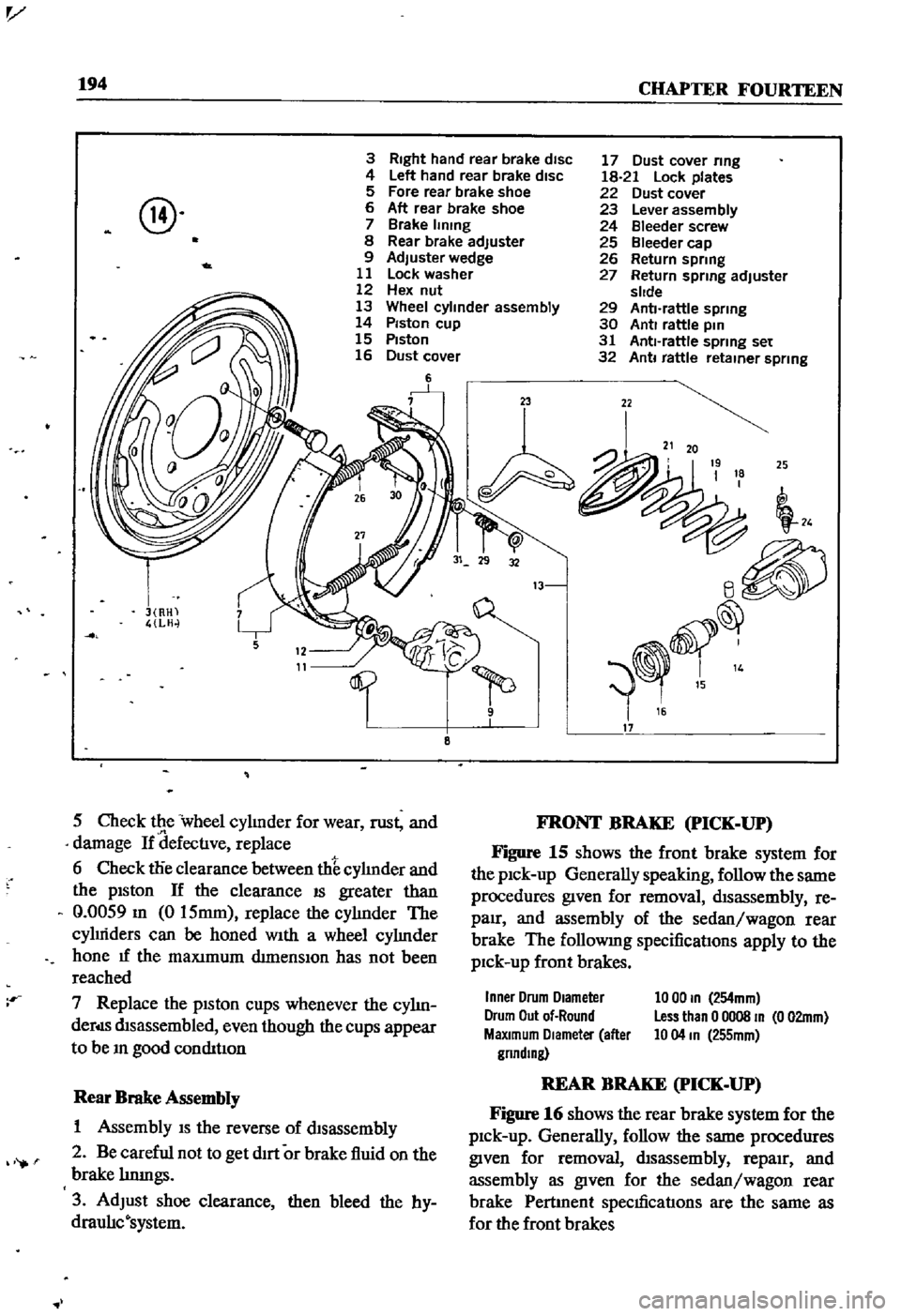
Figure
14
IS
an
exploded
view
of
the
rear
brake
assembly
used
m
the
sedan
and
wagon
Rear
Brake
Removal
and
Disassembly
1
Jack
up
the
rear
of
the
vehicle
and
support
It
on
stands
Remove
the
wheels
2
Release
the
parkIng
brake
DISConnect
the
cross
rod
from
the
lever
of
the
ie
wheel
cylinder
3
Remove
the
brake
drum
4
Remove
the
return
springs
and
take
out
the
brake
shoe
assemblies
5
Disconnect
the
brake
tube
from
the
wheel
cylinder
6
Remove
the
wheel
cylinder
by
removing
dust
cover
plates
and
adJusting
shIms
7
DISassemble
the
wheel
cylinder
by
removing
the
dust
cover
and
snap
nng
8
Remove
the
adJuster
assembly
Rear
Brake
Inspection
d
Repair
Sedan
and
Wagon
I
Inspect
the
brake
druf
1s
for
scoring
signs
of
excessive
heat
and
out
of
round
Repair
or
re
place
the
drums
as
reqUIred
The
following
specificatIons
apply
Drum
Out
of
Round
Inner
Olameter
MaXImum
Diameter
after
IlI1ndmg
Less
than
0
0020
In
0
05mm
8
999
m
228
6mm
1
9040
In
229
6mm
2
Inspect
brake
limngs
for
wear
signs
of
oil
or
grease
and
cracks
If
any
of
these
conditions
are
found
replace
the
linmgs
Have
a
brake
special
ISt
arc
the
limngs
to
match
the
diameter
of
the
drums
after
replacement
If
the
thickness
of
the
limng
is
under
0
0591
m
1
5mm
replace
it
3
Check
the
adjusting
cams
for
smooth
opera
tion
Replace
as
reqUIred
4
Check
the
spnngs
If
they
appear
weak
or
uneven
m
tension
replace
them
Page 199 of 252
v
194
CHAPTER
FOURTEEN
3
Right
hand
rear
brake
disc
4
Left
hand
rear
brake
disc
5
Fore
rear
brake
shoe
6
Aft
rear
brake
shoe
7
Brake
IImng
8
Rear
brake
adjuster
9
Adjuster
wedge
11
Lock
washer
12
Hex
nut
13
Wheel
cylinder
assembly
14
Piston
cup
15
Piston
16
Dust
cover
6
@
5
Check
the
wheel
cylinder
for
wear
rust
and
damage
If
defectIve
replace
6
Check
die
clearance
between
th
cyhnder
and
the
piston
If
the
clearance
18
greater
than
Q
0059
m
0
15mm
replace
the
cylinder
The
cyluiders
can
be
honed
With
a
wheel
cyhnder
hone
If
the
maXImum
dimensIOn
has
not
been
reached
7
Replace
the
piston
cups
whenever
the
cyhn
derds
disassembled
even
though
the
cups
appear
to
be
m
good
condition
Rear
Brake
Assembly
1
Assembly
IS
the
reverse
of
disassembly
2
Be
careful
not
to
get
dirt
or
brake
fluid
on
the
brake
hnnlgs
3
AdJust
shoe
clearance
then
bleed
the
hy
draulIc
system
17
Dust
cover
ring
18
21
Lock
plates
22
Dust
cover
23
Lever
assembly
24
Bleeder
screw
25
Bleeder
cap
26
Return
spring
27
Return
spring
adjuster
slide
29
Anti
rattle
spring
30
Anti
rattle
pin
31
Anti
rattle
spring
set
32
Anti
rattle
retainer
spring
23
22
24
e
17
a
25
FRONT
BRAKE
pICK
UP
Figure
15
shows
the
front
brake
system
for
the
pick
up
Generally
speaking
follow
the
same
procedures
given
for
removal
disassembly
re
pair
and
assembly
of
the
sedan
wagon
rear
brake
The
followmg
specifications
apply
to
the
pick
up
front
brakes
Inner
Drum
Diameter
Drum
Out
of
Round
MaXimum
DIameter
after
gnndlng
10
00
In
254mm
Less
than
0
0008
In
0
02mm
10
04
In
255mm
REAR
BRAKE
pICK
UP
Figure
16
shows
the
rear
brake
system
for
the
pick
up
Generally
follow
the
same
procedures
given
for
removal
disassembly
repaIr
and
assembly
as
given
for
the
sedan
wagon
rear
brake
Pertment
specificatIons
are
the
same
as
for
the
front
brakes