1968 DATSUN 510 cooling
[x] Cancel search: coolingPage 4 of 252
II
CHAPTER
SIX
ENGINE
Cylmder
block
Crankshaft
PistOns
and
connectmg
rods
Cyhnder
head
Camshaft
Valve
mechamsm
Camshaft
dnve
Mamfolds
011
pump
Fuel
pump
Carburetor
Emission
control
devIces
Engme
removal
Engme
dISassembly
Pistons
and
connectmg
rods
Cyhnder
head
Engme
mspectIon
and
replllr
Engme
reassembly
Service
data
and
speCifications
CHAPTER
SEVEN
FUEL
SYSTEM
Air
cleaner
Fuel
strlllner
Fuel
pump
Carburetor
Fuel
tank
1
CHAPTER
EIGHT
COOLING
SYSTEM
DescnptIon
Water
pump
Fan
clutch
Thermostat
Radiator
CHAPTER
NINE
ENGINE
ELECTRICAL
SYSTEM
Starter
Overrunmng
clutch
assembly
ChargIng
ClrcUlt
Alternator
Alternator
output
Voltage
regulator
DIstrIbutor
Condenser
Igrntlon
cod
SpeCifications
Spark
plugs
CHAPTER
TEN
EMISSION
CONTROL
SYSTEM
Exhaust
emiSSIOn
control
Crankcase
emission
control
Air
mJectlon
system
Engme
modifications
Evaporative
emiSSion
control
Exhaust
system
CHAPTER
ELEVEN
CLUTCH
TRANSMISSION
AND
DRIVESHAFT
Clutch
TransmissIon
Master
cyhnder
TransmissIon
data
and
speCIfications
Operating
cyhnder
Dnveshaft
Withdrawal
lever
adjustment
Dnveshaft
data
and
speCIfications
Clutch
system
bleedmg
Automatic
transmIssIon
checks
Clutch
data
and
speCIfications
31
62
84
91
114
127
Page 27 of 252
22
CHAPTER
FOUR
CD
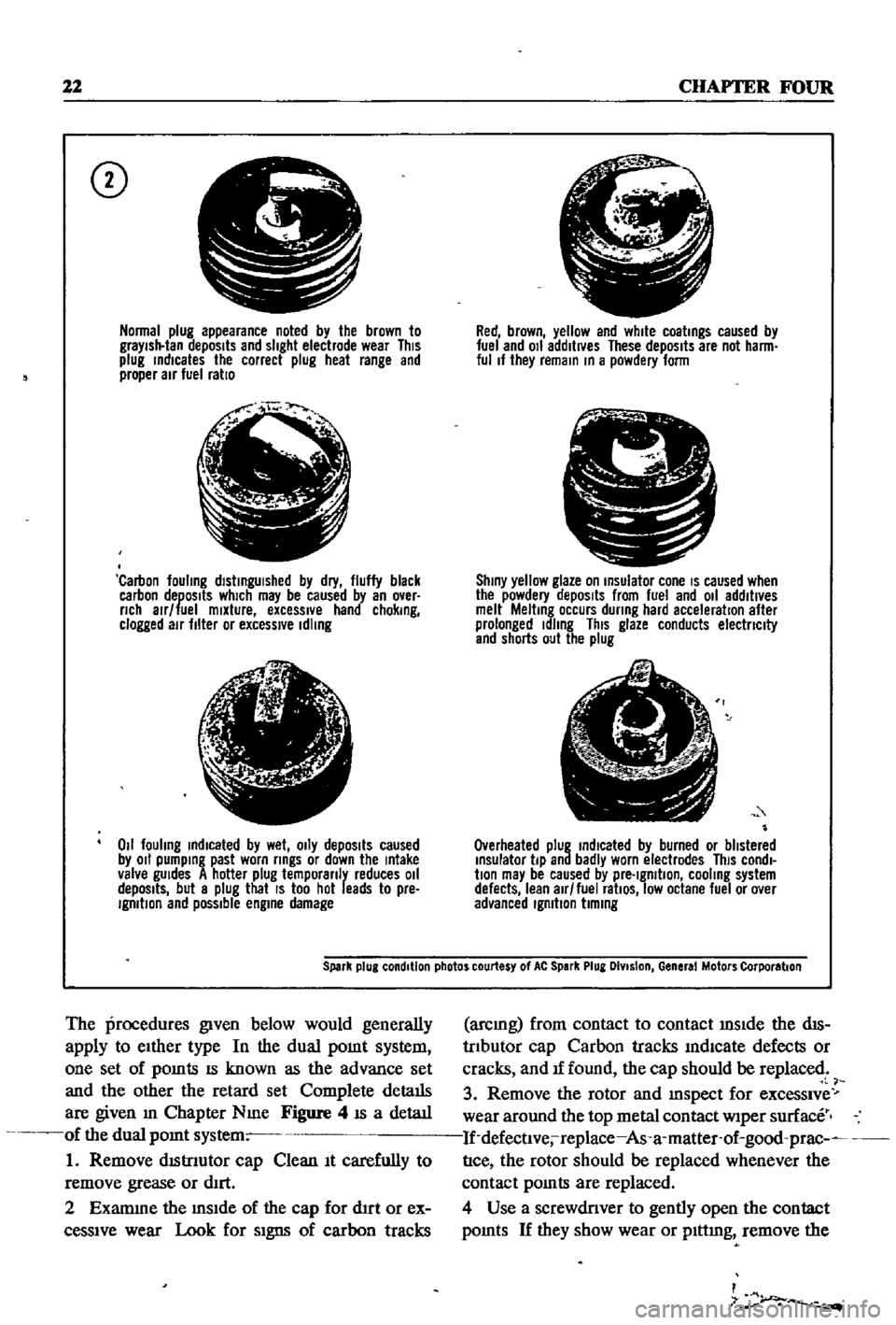
Normal
plug
appearance
noted
by
the
brown
to
graYish
tan
deposits
and
slight
electrode
wear
This
plug
rndlcates
the
correct
plug
heat
range
and
proper
air
fuel
ratio
f
j
l
Carbon
fouling
dlstrngUlshed
by
dry
fluffy
black
carbon
deposits
which
may
be
caused
by
an
over
nch
alr
fuel
mixture
excessIVe
hand
chokrng
clogged
air
filter
or
excessive
Idling
lJ
6
1
4i
Z
011
fouling
rndlcated
by
wet
OIly
depOSits
caused
by
011
pumprng
past
worn
rrngs
or
down
the
rntake
valve
gUides
A
hotter
plug
temporanly
reduces
011
depOSits
but
a
plug
that
IS
too
hot
leads
to
pre
IgmtlOn
and
possible
engrne
damage
Red
brown
yellow
and
white
coatrngs
caused
by
fuel
and
011
additives
These
depOSits
are
not
harm
ful
If
they
remarn
rn
a
powdery
form
C
I
Shrny
yellow
glaze
on
rnsulator
cone
IS
caused
when
the
powdery
depOSits
from
fuel
and
011
additives
melt
Meltrng
occurs
dunng
hard
acceleration
after
prolonged
Idling
This
glaze
conducts
electnclty
and
shorts
out
the
plug
Overheated
plug
rndlcated
by
burned
or
blistered
rnsulator
tip
and
badly
worn
electrodes
This
condl
bon
may
be
caused
by
pre
Igmtlon
cooling
system
defects
lean
air
fuel
ratiOS
low
octane
fuel
or
over
advanced
Igmbon
bmrng
Spark
plug
condition
photos
courtesy
of
At
Spark
Plug
DIvision
General
Motors
Corporation
The
procedures
given
below
would
generally
apply
to
eIther
type
In
the
dual
pomt
system
one
set
of
pomts
IS
known
as
the
advance
set
and
the
other
the
retard
set
Complete
details
are
given
m
Chapter
Nme
Figure
4
IS
a
detaIl
of
the
dual
pomt
system
1
Remove
dIStnutor
cap
Clean
It
carefully
to
remove
grease
or
dIrt
2
Examme
the
mSIde
of
the
cap
for
d1rt
or
ex
ceSSIve
wear
Look
for
SIgns
of
carbon
tracks
arcmg
from
contact
to
contact
mSIde
the
dIS
trIbutor
cap
Carbon
tracks
mdlcate
defects
or
cracks
and
If
found
the
cap
should
be
replaced
3
Remove
the
rotor
and
mspect
for
exceSSIve
wear
around
the
top
metal
contact
wiper
surface
If
defectlve
replace
As
a
matter
of
good
prac
nce
the
rotor
should
be
replaced
whenever
the
contact
pomts
are
replaced
4
Use
a
screwdriver
to
gently
open
the
contact
pomts
If
they
show
wear
or
plttmg
remove
the
I
7
r
Page 89 of 252
CHAPTER
EIGHT
COOLING
SYSTEM
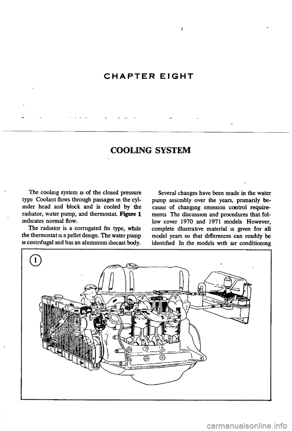
The
coolIng
system
IS
of
the
closed
pressure
type
Coolant
flows
through
passages
In
the
cyl
mder
head
and
block
and
is
cooled
by
the
radIator
water
pump
and
thermostat
Figure
1
mdlcates
normal
flow
The
radIator
is
a
corrugated
fin
type
wh1le
the
thermostat
IS
a
pellet
desIgn
The
water
pump
IS
centnfugal
and
has
an
alummum
dlecast
body
CD
Several
changes
have
been
made
in
the
water
pump
assembly
over
the
years
pnmanly
be
cause
of
changmg
ennSSlon
cootrol
require
ments
The
diSCUSSIOn
and
procedures
that
fol
low
cover
1970
and
1971
models
However
complete
IllustratIve
material
IS
given
for
all
model
years
so
that
dIfferences
can
readIly
be
identIfied
In
the
models
With
aIr
conditionmg
Page 90 of 252
COOLING
SYSTEM
8S
and
In
those
with
exhaust
and
evaporatIve
emIS
sion
control
devIces
a
fan
clutch
IS
combIned
WIth
the
thermostat
to
detect
temperature
m
the
engme
compartlnent
When
the
temperature
nses
the
thermostat
detects
the
change
an
the
fan
clutch
engages
thereby
helpmg
to
cool
the
engme
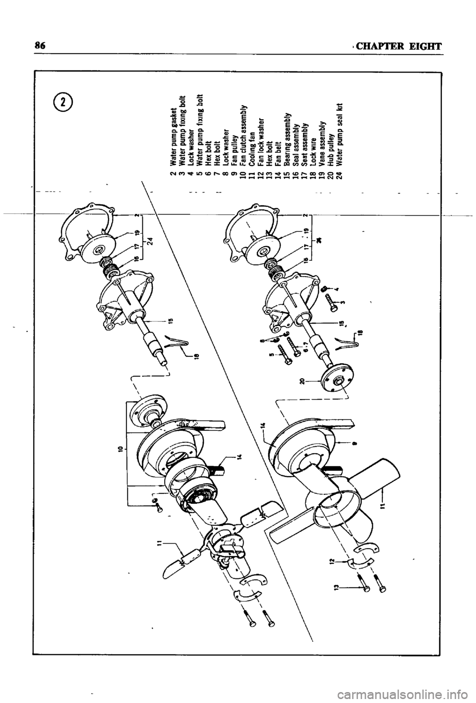
WATER
PUMP
Figure
2
page
86
IS
an
exploded
drawmg
of
the
water
pump
and
fan
assembly
for
1970
to
1971
The
top
half
of
the
IllustratIon
applIes
to
those
models
WIth
exhaust
and
evaporatIve
emiSSIOn
control
systems
The
bottom
half
covers
models
WIth
a
crankcase
emiSSIon
control
deVIce
only
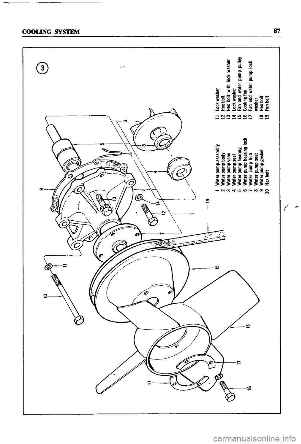
Figure
3
page
87
IS
an
exploded
drawmg
of
the
water
pump
and
fan
assembly
for
1968
models
Without
exhaust
or
evaporatIve
controls
Figure
4
page
88
shows
the
1968
model
With
emISSIon
control
deVIce
As
can
be
seen
from
the
illustratIons
most
dIfferences
eXISt
withIn
the
fan
clutch
assembly
Water
Pump
Removal
1
Remove
upper
and
lower
radIator
hoses
from
the
thermostat
housmg
and
cylmder
block
re
spectIvely
Dram
coolant
from
rad1ator
and
cylInder
block
2
Loosen
the
alternator
mountlng
bolt
and
the
adjustIng
bolt
on
the
alternator
mountIng
bracket
3
Move
the
alternator
toward
the
cylinder
block
untIl
slack
IS
eVIdent
10
the
fan
belt
Re
move
fa
belt
fro
alternator
water
pump
and
crankshaft
pulley
4
It
IS
difficult
to
remove
the
water
pump
from
the
front
housmg
With
the
radiator
and
top
shroud
10
place
so
remove
them
5
Remove
the
bolts
holdmg
the
fan
assembly
to
the
water
pump
and
remove
the
fan
assembly
6
Remove
the
bolts
holdmg
the
water
pump
to
the
front
housmg
as
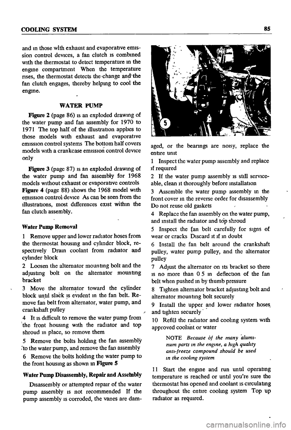
shown
In
Figure
S
Water
Pump
Disassembly
Repair
and
Assembly
Disassembly
or
attempted
repaIr
of
the
water
pump
assembly
IS
not
recommended
If
the
pump
assembly
IS
corroded
the
vanes
are
dam
aged
or
the
bearmgs
are
nOISY
replace
the
entIre
umt
1
Inspect
the
water
pump
assembly
and
replace
If
reqUIred
2
If
the
water
pump
assembly
IS
stIll
serVIce
able
clean
It
thoroughly
before
mstallatIon
3
Assemble
the
water
pump
assembly
m
the
front
cover
10
the
reverse
order
for
disassembly
Do
not
reuse
old
gaskets
4
Replace
the
fan
assembly
on
the
water
pump
and
mstall
the
radiator
and
top
shroud
5
Inspect
the
fan
belt
carefully
for
SIgnS
of
wear
or
cracks
DIscard
It
If
10
doubt
6
Install
the
fan
belt
around
the
crankshaft
pulley
water
pump
pulley
and
the
alternator
pulley
7
Adjust
the
alternator
on
Its
bracket
so
there
IS
no
more
than
0
5
10
deflection
of
the
fan
belt
when
pushed
10
by
thumb
pressure
8
TIghten
alternator
bracket
adjustIng
bolt
and
alternator
mountmg
bolt
securely
9
Install
the
upper
and
lower
rad1ator
hoses
and
tIghten
securely
10
Refill
the
radIator
and
coolmg
system
With
approved
coolant
or
water
NOTE
Because
of
the
many
aluml
num
parts
In
the
engine
a
hIgh
qualIty
antI
freeze
compound
should
be
used
In
the
cooling
system
11
Start
the
engme
and
run
untIl
operatIng
temperature
IS
reached
or
untIl
you
re
sure
the
thermostat
has
opened
and
coolant
IS
CIrCulatIng
throughout
the
entIre
coolIng
system
Top
up
radIator
as
reqUIred
Page 91 of 252
10
f
e
2
Weter
pump
gasket
3
Water
pump
tlXlng
bolt
4
Lock
washer
5
Water
pump
tlXlng
bolt
6
Hex
bolt
7
Hex
bolt
8
Lock
washer
9
Fan
pulley
10
Fan
clutch
assembly
11
Cooling
tan
12
Fan
lock
washer
13
Hex
bolt
14
Fan
belt
15
Dealing
assembly
16
Seal
assembly
17
Seatassembly
18
Lock
wire
19
Vane
assembly
20
Hub
pulley
24
Water
pump
seal
kit
Illl
t
l
Page 92 of 252
10
9
8
n
o
o
19
1
Water
pump
assembly
11
lock
washer
2
Water
pump
body
12
Hex
bolt
3
Water
pump
ane
13
Hex
bolt
With
lock
washer
4
Water
pump
seal
14
loc
l
washer
17
6
5
Water
pump
beanng
15
Fan
and
water
pump
pulley
6
Water
pump
bee
ring
lock
16
Cooling
tan
7
Water
pump
hub
17
Fan
and
water
pump
lock
8
Water
pump
seat
washer
9
Water
pump
gasket
18
Hex
bolt
10
Hex
bolt
19
Fen
belt
I
I
Page 94 of 252
COOLING
SYSTEM
89
FAN
CLUTCH
Fan
Clutch
Operation
and
Inspection
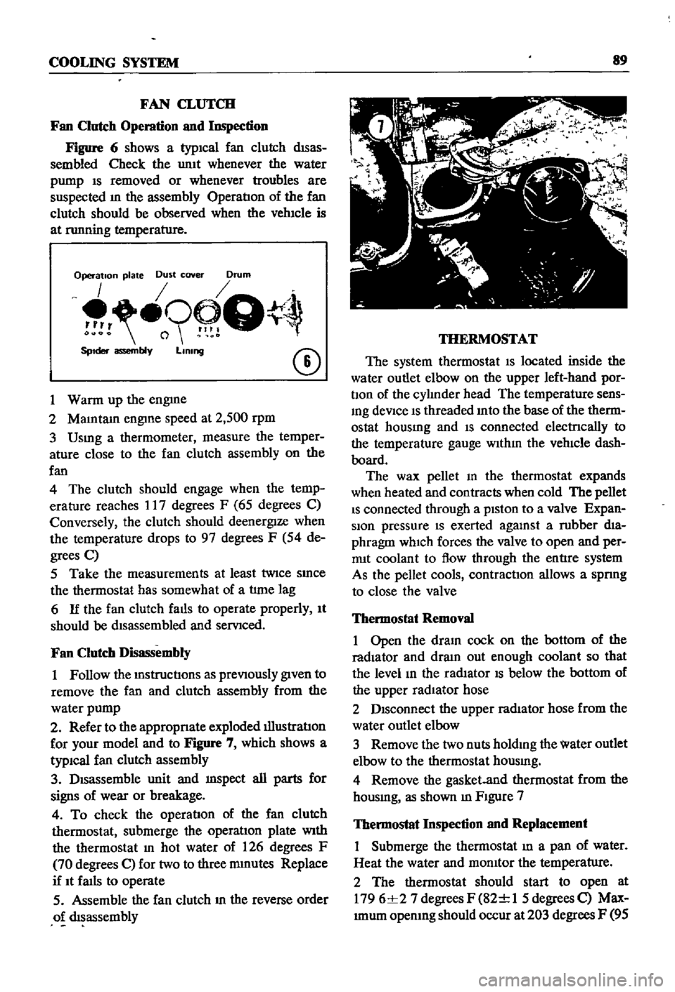
Figure
6
shows
a
typICal
fan
clutch
dISas
sembled
Check
the
umt
whenever
the
water
pump
IS
removed
or
whenever
troubles
are
suspected
m
the
assembly
OperatIon
of
the
fan
clutch
should
be
observed
when
the
vehIcle
is
at
nmning
temperature
Operation
plate
Dust
cover
Drum
o9
Q
SpIder
assembly
LIning
CD
1
Warm
up
the
engme
2
MaIntam
engIne
speed
at
2
500
rpm
3
Usmg
a
thermometer
measure
the
temper
ature
close
to
the
fan
clutch
assembly
on
the
fan
4
The
clutch
should
engage
when
the
temp
erature
reaches
17
degrees
F
65
degrees
C
Conversely
the
clutch
should
deenergIze
when
the
temperature
drops
to
97
degrees
F
54
de
grees
C
5
Take
the
measurements
at
least
twice
SInce
the
thermostat
has
somewhat
of
a
tlme
lag
6
If
the
fan
clutch
falls
to
operate
properly
It
should
be
dIsassembled
and
servIced
Fan
Clutch
Disassembly
1
Follow
the
mstructIons
as
prevIOusly
gIven
to
remove
the
fan
and
clutch
assembly
from
the
water
pump
2
Refer
to
the
appropnate
exploded
illustratIon
for
your
model
and
to
Figure
7
which
shows
a
typiCal
fan
clutch
assembly
3
DIsassemble
unit
and
mspect
all
parts
for
signs
of
wear
or
breakage
4
To
check
the
operatIon
of
the
fan
clutch
thermostat
submerge
the
operatIon
plate
With
the
thermostat
In
hot
water
of
126
degrees
F
70
degrees
C
for
two
to
three
mmutes
Replace
if
It
faIls
to
operate
5
Assemble
the
fan
clutch
m
the
reverse
order
o
dIsassembly
THERMOSTAT
The
system
thermostat
IS
located
inside
the
water
outlet
elbow
on
the
upper
left
hand
por
bon
of
the
cylInder
head
The
temperature
sens
Ing
deVice
IS
threaded
Into
the
base
of
the
therm
ostat
housmg
and
IS
connected
electrlcally
to
the
temperature
gauge
WIthIn
the
vehIcle
dash
board
The
wax
pellet
m
the
thermostat
expands
when
heated
and
contracts
when
cold
The
pellet
IS
connected
through
a
pIston
to
a
valve
Expan
sion
pressure
IS
exerted
agalUst
a
rubber
dIa
phragm
which
forces
the
valve
to
open
and
per
rrut
coolant
to
flow
through
the
entIre
system
As
the
pellet
cools
contractIOn
allows
a
spnng
to
close
the
valve
Thermostat
Removal
1
Open
the
draIn
cock
on
the
bottom
of
the
radiator
and
dram
out
enough
coolant
so
that
the
level
In
the
radIator
IS
below
the
bottom
of
the
upper
radIator
hose
2
DIsconnect
the
upper
radIator
hose
from
the
water
outlet
elbow
3
Remove
the
two
nuts
holdIng
the
water
outlet
elbow
to
the
thermostat
housmg
4
Remove
the
gasket
and
thermostat
from
the
housmg
as
shown
m
FIgure
7
Thermostat
Inspection
and
Replacement
Submerge
the
thermostat
In
a
pan
of
water
Heat
the
water
and
momtor
the
temperature
2
The
thermostat
should
start
to
open
at
1796
1
27
degrees
F
82
1
1
5
degrees
C
Max
Imum
opemng
should
occur
at
203
degrees
F
95
Page 118 of 252
ENGINE
ELECI
RICAL
SYSTEM
113
i
Normal
plug
appearance
noted
by
the
brown
to
graYlsll
lan
depOSits
and
slight
eleclrode
wear
This
plug
indicates
the
correct
plug
heal
range
and
proper
air
fuel
ratio
jI
Jo
t
Ql
i
Carbon
fouhng
distinguished
by
dry
fluffy
black
carbon
depOSits
which
may
be
caused
by
an
over
rich
alr
lue
mixture
excessive
hand
choking
clogged
air
filler
or
excessl
e
Idling
t
I
j
if
r
l
1
tfc
ji
0
1
fouling
indicated
by
wet
o
ly
depOSits
caused
by
011
pumping
past
worn
rings
or
down
the
Intake
valve
gUIdes
A
hotter
plug
temporanly
reduces
011
depOSits
but
a
plug
that
IS
too
hot
leads
to
pre
Ignition
end
possible
engine
damage
@
Red
brown
yellow
and
white
coatings
caused
by
luel
and
011
addltl
es
These
depOSits
are
not
harm
ful
If
they
remain
In
a
powdery
lorm
pr
11
L
J
J
S
C
ShinY
yellow
glaze
on
Insulalor
cone
IS
caused
when
the
powdery
depOSits
from
fuel
and
011
addltl
es
melt
Melting
occurs
during
hard
acceleration
alter
prolonged
Idling
This
glaze
conducts
electnclty
and
shorts
out
the
plug
e
1
A
I
A
I
7
Overheated
plug
indIcated
by
burned
or
blistered
Insulator
tiP
and
badly
worn
electrodes
ThiS
condl
J
tlon
may
be
caused
by
pre
Ignition
cooling
system
defects
lean
alr
luel
ratiOS
low
octane
luel
or
o
er
advanced
Ignition
timing
Spark
plUI
condition
photos
courtesy
of
AC
SPIr1l
Plug
Olv
s
on
Gene
MolDrs
Corporlllon